80-9360-1029-020 Rev 6 01/23
Copyright © 2019, 2020, 2023, ASSA ABLOY Accessories and Door Controls Group, Inc. All rights reserved. Reproduction in whole
or in part without the express written permission of ASSA ABLOY Accessories and Door Controls Group, Inc. is prohibited.
2
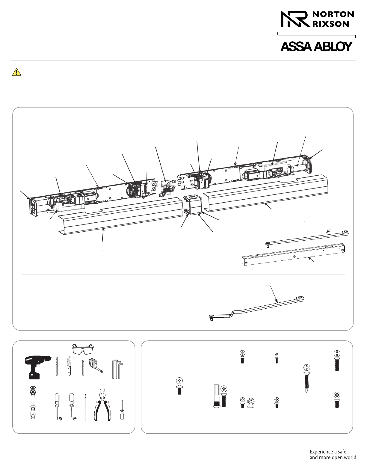
D6011/D6051 Series Double Unit Pull Side Power Operator
Contents
Certifications and Standards.................................................................. 2
Product Safety Warnings . . . . . . . . . . . . . . . . . . . . . . . . . . . . . . . . . . . . . . . . . . . . . . . . . . . . . . . . . . . . . . . . . . . . . 2
General Information .......................................................................... 3
Before You Begin .............................................................................4
Technical Data ................................................................................4
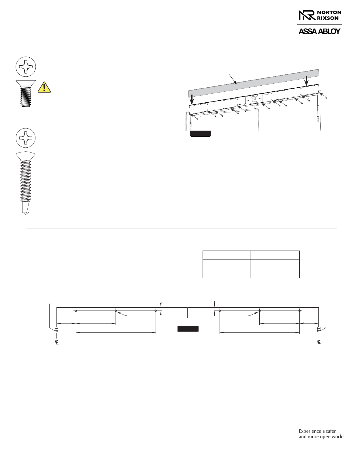
Prepare Frame and Door ..................................................................... 5
Install Operator ...............................................................................8
Install Track and Arm . . . . . . . . . . . . . . . . . . . . . . . . . . . . . . . . . . . . . . . . . . . . . . . . . . . . . . . . . . . . . . . . . . . . . . . . . 11
Adjustments ..................................................................................12
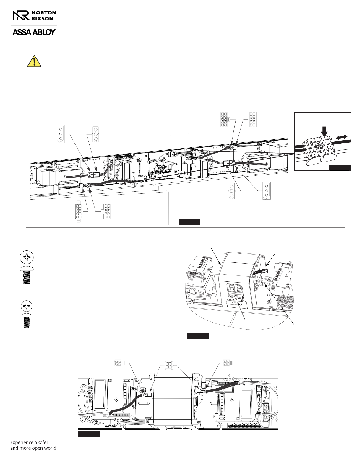
Power Operators ..............................................................................13
Sync Operators................................................................................14
Finalize Installation ...........................................................................15
General Electrical Information ................................................................15
Wiring Options................................................................................16
Basic Double Door Wiring Diagrams Using Factory Pre-Wired Connection ..................18
Troubleshooting Guide . . . . . . . . . . . . . . . . . . . . . . . . . . . . . . . . . . . . . . . . . . . . . . . . . . . . . . . . . . . . . . . . . . . . . . 27
D6011/D6051 Template . . . . . . . . . . . . . . . . . . . . . . . . . . . . . . . . . . . . . . . . . . . . . . . . . . . . . . . . . . . . . . . . . . . . . . . 28
Certifications and Standards
yETL Certified: Operator conforms to ANSI/UL standard 325 for automatic closing doors and UL10C Positive Pressure
Fire Test for Door Assemblies.
yANSI A156.19: These products are designed to conform to this specification “for power assist and low energy power
operated doors.” These products are designed to exceed all the requirements for “Low Energy Power Operated Door”.
yAmericans with Disabilities Act (A.D.A.): These door operators can be installed and adjusted to conform with A.D.A.
regulations.
yANSI A117.1: These door controls permit door assemblies to conform to the requirements of this specification “for
buildings and facilities - providing accessibility and usability for physically handicap people”.
Product Safety Warnings
WARNING: To reduce risk of injury to person, use this operator only with Pedestrian Swing doors. FOR INDOOR USE ONLY
1. READ AND FOLLOW ALL INSTRUCTIONS.
2. Install only on a properly operating and balanced door.
A door that is operating improperly could cause severe
injury. Have qualified service personnel make repairs to
any hardware before installing the operator.
3. Remove, or make inoperative, all locks (unless
mechanically and/or electrically interlocked to the power
unit) that are connected to the door before installing the
operator.
4. Do not connect the door operator to the source power
until instructed to do so.
5. Never let children operate or play with door controls.
Keep remote control (when provided) away from
children.
6. Personnel should keep away from a moving door in
motion.
7. Test door’s features at least once a month. After
adjusting either force or limit of travel, retest door
operator’s features. Failure to adjust operator
properly may cause severe injury or death.
8. KEEP DOOR PROPERLY OPERATING. An improperly
operating door could cause severe injury or death.
9. SAVE THESE INSTRUCTIONS.
Approved 2023-01-24