Telecrane F21-12S User manual

November 7, 2004
Ref: TCM260904
Rev: 0.1
TELECRANE REMOTE CONTROLS
F21 12/6 S/D
MANUAL
111 Woodhurst Road,
Stanground,
Peterborough,
Cambridgeshire.
PE2 8PQ
United Kingdom.
Tel: 07092 242773
Fax: 07092 182470

TCM260904 Rev 0.1
TCM260904 Page 2 of 31
CONTENTS
Installation & Operation............................................................................................................................................................................................3
Precautions of Operation.......................................................................................................................................................................................3
Attention...........................................................................................................................................................................................................3
Precautions........................................................................................................................................................................................................4
Procedures of emergency..................................................................................................................................................................................4
General Characteristic...............................................................................................................................................................................................5
General Specifications ..........................................................................................................................................................................................5
Transmitter Specifications ....................................................................................................................................................................................5
Receiver Specifications.........................................................................................................................................................................................5
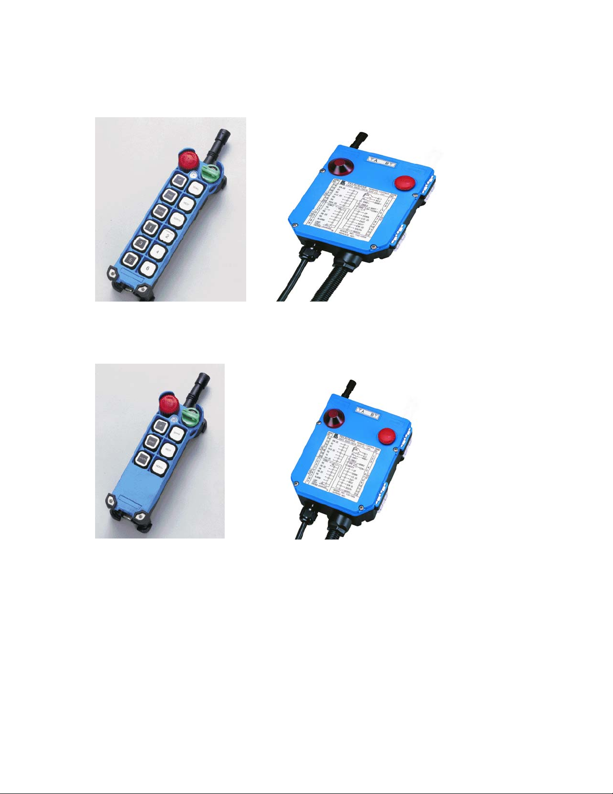
F21-12D/12S system ........................................................................................................................................................................................6
F21-6D/6S system: ...........................................................................................................................................................................................6
Transmitter parts...............................................................................................................................................................................................7
Installation.................................................................................................................................................................................................................9
Precautions during installation..............................................................................................................................................................................9
Receiver Installation Instructions........................................................................................................................................................................10
Preparation for Installation .............................................................................................................................................................................10
Installation of proper power source............................................................................................................................................................10
Installation Sequence......................................................................................................................................................................................11
Notes...............................................................................................................................................................................................................11
Operation.................................................................................................................................................................................................................12
Start Up...............................................................................................................................................................................................................12
Power indicating functions of LED display....................................................................................................................................................12
Power-On operation............................................................................................................................................................................................12
Any pushbutton Power-On Mode...................................................................................................................................................................12
“Start” (Magnetic Key switch) Power-On Mode............................................................................................................................................12
E.U. standard Power-On Mode.......................................................................................................................................................................13
Software Power-On Mode ..............................................................................................................................................................................13
Acceleration / Deceleration Operation............................................................................................................................................................13
Inching Operation...........................................................................................................................................................................................13
Change of Frequency......................................................................................................................................................................................14
Procedure for changing operation frequency:.............................................................................................................................................15
Enter password operation................................................................................................................................................................................15
Function Setting ......................................................................................................................................................................................................16
Start Switch Function Setting:.............................................................................................................................................................................16
Up/Down Pushbutton Function Setting:..............................................................................................................................................................16
East/West Pushbutton Function Setting:.............................................................................................................................................................17
South/North Pushbutton Function Setting:..........................................................................................................................................................17
R1/R2Pushbutton Function Setting:....................................................................................................................................................................18
R3/R4 Pushbutton Function Setting:...................................................................................................................................................................18
R5/R6 Pushbutton Function Setting....................................................................................................................................................................19
Other Transmitter Functions ...............................................................................................................................................................................20
Other Receiver Functions:...................................................................................................................................................................................23
Setting Of Channels............................................................................................................................................................................................24
Password code setting.........................................................................................................................................................................................24
Function setting by radio: ...................................................................................................................................................................................24
Inspection and Maintenance....................................................................................................................................................................................25
Inspection............................................................................................................................................................................................................25
Maintenance........................................................................................................................................................................................................25
Troubleshooting.......................................................................................................................................................................................................26
Self-Diagnostics..................................................................................................................................................................................................26
Notes:..............................................................................................................................................................................................................26
Transmitter Malfunctions and Solutions.............................................................................................................................................................27
Receiver Malfunction and Correction.................................................................................................................................................................28
Malfunction Identification. .................................................................................................................................................................................30
Revision History......................................................................................................................................................................................................31

TCM260904 Rev 0.1
TCM260904 Page 3 of 31
INSTALLATION & OPERATION
PRECAUTIONS OF OPERATION
ATTENTION
Please carefully read the manual before installing and operating this device.
Due to the complex nature of this equipment it is necessary to read the entire manual before installation.
Never dismantle the equipment by any unauthorized personnel, or equipment may be damaged.
This manual is for reference only. Pleases consult your distributor for further assistance.
The equipment has been strictly tested for quality before delivery from our plant. However, this equipment must not be used in
dangerous situations or where damage may result.
After finishing operation of TELECRANE shut off main power to the crane, power to receiver, and remove transmitter key. If
transmitter’s power is controlled by “rotary key switch”, then turn the key to “OFF” position and remove it.
Transmitter should be placed in a safe area when not in use to avoid accidental pressing of buttons.
The crane should be equipped with main power relay, limit switch and other safety devices.
The GND (ground) of the receiver must be in contact with the metal part of the crane or electrical shock may occur.
Don’t use equipment during lightening or high electrical interference conditions.
Make sure that the batteries are in good condition and power for receiver is correct.
Installation and maintenance should only be done while the crane’s main power is off to prevent electrical shock.
The contents of this manual may be amended by the manufacturer without notice.
The manufacturer may introduce new functions to the equipment as necessary; therefore, the descriptions may change.
The patent and related documents for the equipment belong to The Manufacturer and they aren’t allowed to be used by others
without permission.
F21 series systems adopt many of patents belong to The Manufacturer. and its associated companies.

TCM260904 Rev 0.1
TCM260904 Page 4 of 31
PRECAUTIONS
Operating in an industrial facility is highly dangerous; therefore, operator must have adequate training in using TELECRANE
with this in mind.
Those who operate the machine should be healthy and have good judgment in regards to safety.
Although the F21 transmitter is very durable and weather resistant care should be taken not to expose it to severe impact or
pressure.
During operation, if the power supplied from transmitter’s batteries is insufficient, the transmitter will send out EMS signal
first to de-energize all of motion relays inside the receiver to stop crane’s moving (Notice: the motions which are set as
”Bypass EMS” will continuously move.), and then the LED indicator and buzzer on transmitter will light and sound
continuously. At this time, they need to be replaced with AA size alkaline batteries. All four batteries should be replaced at the
same time. Don’t use manganese-zinc batteries because of their corrosive properties.
If the severe interference occurs you should stop using the equipment at once.
The standard voltage of rechargeable nickel-cadmium battery is 1.2 volts with capacity 500-800 mAH. When they are used in
F21 system, the operating time will be shorter.
Please take the battery out when the equipment will not be used for a long time.
Be sure to know the “Procedures of emergency” in case of emergency.
PROCEDURES OF EMERGENCY
The F21 system has various protections to guard against different emergencies including strict security code checking and
automatic monitoring of parts failure. The F21 system has isolation circuitry to protect from outside voltage surges and
interference. In the event of sensing an emergency situation the F21 will perform an emergency stop of the equipment. It is
important to properly install the F21 system so it can perform the emergency shutdown properly.
In case of an Emergency, please follow the steps below and ask the distributor for service immediately.
(1) Press EMS button.
(2) Pull the magnetic key out of the transmitter. If transmitter’s power is controlled by “rotary key switch”, then
you need turn the key to “OFF” position to remove it.
(3) Switch off the main power of crane.
(4) Advise the distributor to find out the reason.

TCM260904 Rev 0.1
TCM260904 Page 5 of 31
GENERAL CHARACTERISTIC
GENERALSPECIFICATIONS
- Operating Frequency--------------------- : 415 ~ 483 MHz (set by software)
- Hamming Distance ----------------------- : ≧4
- I.D. Code----------------------------------- : 232; more than 4 billion sets (set by factory, never repeated)
- Temperature Range----------------------- : -35℃~ +75℃
- Channel Spacing-------------------------- : 5KC/6.25KC or integral multiple (set by software)
- Maximum Operating Range------------ : Up to 100 Meters
- Structure----------------------------------- : Fibre-Nylon
- Protection Degree------------------------ : IP 65
TRANSMITTER SPECIFICATIONS
- Power Supply----------------------------- : Four 1.5volt Alkaline or Rechargeable Batteries (AA Size)
- RF Power---------------------------------- : <10 mW
- Modulation-------------------------------- : ≤±2.5KHz; NBFM
- Pushbutton Type-------------------------- : Two step Mechanical Switch
- Dimensions-------------------------------- : 186x61x51mm (excluding protrusion)
- Weight------------------------------------- : about 360g (including batteries)
RECEIVER SPECIFICATIONS
- Power Supply----------------------------- : AC 110/220/380V (50/60Hz) (tolerance±10%)
- Sensitivity---------------------------------- : −110DBm (Date Error Rate <10−3)
- Image Rejection--------------------------- : > 60dB
- Rejection of Adjacent Channels ------- : > 80dB (± 20KC)
- Output Relays----------------------------- : 10A/250VAC; 8A/30VDC
- Dimensions-------------------------------- : 200x162x107mm (excluding protrusion)
- Weight------------------------------------- : about 1640g (excluding wire cable)

TCM260904 Rev 0.1
TCM260904 Page 6 of 31
F21-12D/12S SYSTEM
F21-6D/6S SYSTEM:
(1)Transmitter, one unit. (2)Receiver, one unit.

TCM260904 Rev 0.1
TCM260904 Page 7 of 31
TRANSMITTER PARTS
ANTENNA
Rotary Key
Switch
Stop Button
LED indicator
Motion Buttons
Motion Buttons
Auxiliary Buttons
Auxiliary Buttons
Battery Cover

TCM260904 Rev 0.1
TCM260904 Page 8 of 31
Receiver’s parts
Antenna
Receiver/
Decoder
Module
(
inside
)
Relay
Module
(
inside
)
Transformer
(inside)

TCM260904 Rev 0.1
TCM260904 Page 9 of 31
INSTALLATION
PRECAUTIONS DURING INSTALLATION
(1) Observe all safety precautions when climbing the crane.
(2) Turn off the main power source of crane before installation to avoid electric shock.
(3) Receiver must be installed in such a way that it will not touch any part of the building during the operation.
(4) Receiver must be fastened securely.
(5) Two external antennas must be used when receiver is installed in a metal box.
(6) Before installation, inspect the crane’s safety devices, and make sure everything is in proper working
condition.
(7) Make sure you understand the crane circuits and power distribution as well as the function setting of remote
controller, to avoid incorrect wiring.
(8) To avoid any interference, the Receiver must be away from motors, frequency converter and power cable
(show as below).
(9) The Receiver should be installed on the top of the electrical control box. Don’t mount the receiver inside .
Receiver
M
Motor
Cable
Frequency
Converter
(
Correc
t
)
Antenna
Cable
Receiver
⌧
(Incorrect)
(Electrical
control box
)
Receiver
Cable
☺
(Electrical
control box)
As far as possible

TCM260904 Rev 0.1
TCM260904 Page 10 of 31
RECEIVER INSTALLATION INSTRUCTIONS
PREPARATION FOR INSTALLATION
(1) Provide all necessary tools.
(2) Select a proper location.
(3) Select a stable place.
(4) Select a place where you can see the Receiver or Antenna.
(5) Select a place where there are no sparks, e.g. keep away from motors, relays, magnetic switches and power
cables.
(6) Keep away from high-voltage wiring and devices.
(7) The Receiver case must be at least 3 cm away from other obstacles.
INSTALLATION OF PROPER POWER SOURCE
The input power source for the receiver can be 110/220/380 VAC (50/60 Hz) etc. After the power source is confirmed, one must
select the proper connector for the voltage applied to the relay module transformer primary winding.
Selective power supply for F21-12S/12D as illustration as below:
There are 3 kinds of voltage (110V/220V/ 380V) supplied in F21-12S/12D
This could be set as required before shipment, or follow the procedures to change the voltage you need.
(1) Turn off the Receiver.
(2) Pull out the power source plug from the previous voltage position
(3) Plug in the power source plug to the voltage you need.
(4) Complete.
Note: If the voltage you need is 48V/62V/110V, please contact distributor.
Selective power supply for F21-6D as illustration as below:
There are 2 kinds of voltage (110V/220V) supplied in F21-6D
This could be set as required before shipment, or follow the procedures to change the voltage you need.
(1) Turn off the Receiver.
(2) Using tool to pull out the black connector from the previous voltage position.
(3) Using tool to plug in the black connector to the voltage you need.
(4) Complete.
110V 220V
110V 220V 380V
Black connector
Power source plug

TCM260904 Rev 0.1
TCM260904 Page 11 of 31
INSTALLATION SEQUENCE
(1) Turn off the main power for the crane.
(2) Attach the template (provided) for the receiver to the proper place.
(3) Drill the holes for the screws, mount receiver, and then secure the receiver with 6mm nuts on the vibration-
resistant feet.
(4) Connect the cables to the control circuit of the crane according to the receiver’s wiring chart and control
contact diagram.
NOTES
(1) Inspect and make sure that all wires are connected correctly.
(2) The earth ground for the remote controller and crane must be properly connected to ensure safety.
(3) Secure the cables between the receiver and crane so that the cable bracket will not wear through due to the
vibration of the crane.
(4) Open the top cover of the receiver and turn the Relay module’s Run/Test switch to the “Test” position.
(5) Turn on the main power for the crane.
(6) Operate the transmitter to test all functions and make sure they all operate correctly as shown by the LED
indicators.
(When the Run/Test switch is set to the “Test’ position, the relays will not function, but the LEDs will
display)
(7) Turn the Run/Test switch to the “Run” position and secure the top cover to the receiver with screws.
(8) This completes the installation of the receiver.

TCM260904 Rev 0.1
TCM260904 Page 12 of 31
OPERATION
START UP
Remove the cover of battery box.
(1) Install 4 Fresh AA-size batteries in the battery box. Make sure the “+” and “-” directions are correct.
(2) Attach back the battery cover.
Note: Transmitter will sound two-long beeps to indicate the correct installation.
(3) Turn on the power according to the “Power-On Modes” (see below).
Note: LED indicator will flash with red colour if proper procedures are not followed.
(4) Operate transmitter by pressing each pushbutton.
(5) After operation, perform the following procedures in sequence: (1) Press EMS mushroom, (2) rotate key
counter-clock-wise to the “OFF” position, (3) remove key and keep it in a safe place, (4) remove batteries if
not used for a long period.
POWER INDICATING FUNCTIONS OF LED DISPLAY.
Green:
Sufficient power to operate transmitter.
(In order to save power, one can program to turn off LED display when power is sufficient.)
Yellow:
Power is depleting, warning sound occurs every 4 seconds
(can be switched off and sound interval can be set by software).
Operation must be stopped immediately (for example: lower the goods to ground) to replace batteries.
Red:
Insufficient power.
In addition to red LED, warring sound will continue and transmitter will no longer function.
Transmitter will send out an emergency stop signal to the receiver due to insufficient power.
Operator should avoid this situation in order to maintain the safety of operation.
POWER-ON OPERATION
Power-on means that the Main-Relay on receiver will energize as soon as receiving the control data from transmitter and then
receiver keep in condition of standby for continuous control. There are 4 different ways of “Power-On mode” could be setting.
ANY PUSHBUTTON POWER-ON MODE
(1) Rotate “EMS” mushroom clockwise 45º and pull out.
(2) Turn key clockwise to “ON” position.
(3) Press any pushbutton on the transmitter (or A, B switch). This will turn on the power as well as execute the
function of pushbutton.
“START”(MAGNETIC KEY SWITCH)POWER-ON MODE
(1) Rotate “EMS” mushroom clockwise 45º and pull out.
(2) Turn Key switch clockwise to “ON” position.
(3) Turn Key switch 45º beyond “ON” position to turn on power.
Note: When setting is on “Any pushbutton power-on” or “Start pushbutton power-on”, the transmitter is in the “non-
continuous” mode (i.e. pushbutton must be pressed to operate the function), it can save power.

TCM260904 Rev 0.1
TCM260904 Page 13 of 31
E.U. STANDARD POWER-ON MODE
(1) Rotate “EMS” mushroom clockwise 45º and pull out.
(4) Turn Key switch clockwise to “ON” position.
(2) Turn Key switch 45º beyond “ON” position to turn on power.
(3) After 3 minutes of non-operation, transmitter will send out an emergency stop signal to the receiver. When
this occurs, one must turn the magnetic key counter-clockwise to the “OFF” position, then turn the key
clockwise to the “ON” position, and press “Start” pushbutton to turn on the power.
Note:When setting is on “E.U. standard” Power-on Mode, the transmitter is in the continuous mode.
SOFTWARE POWER-ON MODE
This “Power-On” mode is controlled by the software. It consists of:
(1) Whether the receiver Power-Off automatically when no operation for a period of time.
(2) Whether a password is required to turn on power.
(3) Whether an “emergency stop” signal will be sent out…
etc.
ACCELERATION /DECELERATION OPERATION
(1) “South” pushbutton is the acceleration pushbutton; “North” pushbutton is the deceleration pushbutton.
(2) When a motion is in the second speed, quick touch of acceleration pushbutton will double the speed.
Repeated touch of acceleration pushbutton will increase the speed up to 5 times.
(3) To reduce the speed, touch the deceleration pushbutton. Repeated touch of deceleration pushbutton will
reduce to the second speed.
Note:
(1) When accelerate/decelerate, the motion pushbutton must be depressed and held in the second speed. If
motion pushbutton is released, there will be no acceleration/deceleration and speed will return to zero.
(2) Press “North” pushbutton will perform the “Alarm” function if the speed is reduced to the second speed.
INCHING OPERATION
(1) “South” pushbutton is set for “inching” pushbutton.
(2) Press and hold inching pushbutton.
(3) Press any motion pushbutton to perform the inching motion.
Note: The other pushbutton of transmitter must be released before press inching pushbutton.

TCM260904 Rev 0.1
TCM260904 Page 14 of 31
CHANGE OF FREQUENCY
This remote controller provides 3 operating frequencies. When remote controller is interfered by radio wave and can’t
operate properly, the operator can change the transmitter’s frequency according to the following procedures without
changing the channel in the receiver. This eliminates the trouble of climbing to the receiver.
Note 1: From the transmitter, one can depress the corresponding pushbutton to change operation frequency. In the meantime,
LED indicator displays different colours to show the operation frequency as follows:
Operation frequency LED Colour Corresponding pushbutton
Frequency A Red “Up” pushbutton
Frequency B Yellow “Down” pushbutton
Frequency C Green “East” pushbutton
Note 2: From the transmitter, one can follow to the below-mentioned procedures to check the operation frequency.
(1) Press EMS mushroom.
(2) Turn security key to “Off” position and then turn security key clockwise from “Off” to “On” position.
(3) At this moment, LED indicator will display the corresponding colour to show the present operation frequency
of transmitter.
Note 3: Both receiver and transmitter must be in the same operation frequency to operate properly. (e.g. both in Frequency A,
or B, or C).
Note 4: Channels 1 to 256 can be set by Dip switch in the receiver or set by software.
A1A2……………… …..….A256 B1 B2…… ……. C1C2………………………. C256
Dip switch in the receiver is an 8-bit for 256 channels. If current setting is channel 16, one can choose among frequency A16,
B16, C16.
˙Bandwidth of each section and separation between channels can be
set by software. e.g. A1=430,000MHz A2=430,025MHz…..
A255=436,375MHz; B1=436,400MHz…etc.

TCM260904 Rev 0.1
TCM260904 Page 15 of 31
PROCEDURE FOR CHANGING OPERATION FREQUENCY:
Step Action Remark
1 Press EMS mushroom.
2 Turn key to “Off” position.
3
Depress and hold the pushbutton in accordance with the
frequency that you want to change.
Note: The pushbutton must be depressed and held until step 6
is completed.
4 Turn key clockwise from “Off” to “On” position
5 Turn key counter-clockwise from “On” to “Off” position once
LED indicator is ceased flashing.
6 Compete
7 Power-On according to the proper procedure described
previously and return to normal operation.
1. “Up” pushbutton
= Frequency A
2. “Down” pushbutton
= Frequency B
3. “East” pushbutton
= Frequency C
ENTER PASSWORD OPERATION
(1) Rotate “EMS” mushroom clockwise 45º and pull out.
(2) Turn key clockwise to “ON” position.
(3) Press the pushbutton sequentially to enter password within 10 seconds. (Remark: This time duration of
“Password Complete” can be set by software. At the duration of “Password Complete” the LED indicator will
flash with Green colour.)
(4) The buzzer of transmitter will sound one-long sound to indicate the password is correct. After buzzer turns
off, Power-On according to the proper procedure and return to normal operation.
(5) If password is incorrect then the buzzer will sound with two-short sound and one–long sound. Enter the
correct password again after buzzer is turned off.
Note 1: The function of password can be set by software in order to avoid unauthorized people to use remote controller.
Note 2: One must re-enter password to return to normal operation if EMS mushroom has been pressed (or “emergency stop”
signal has been transmitted due to transmitter auto power off).

TCM260904 Rev 0.1
TCM260904 Page 16 of 31
FUNCTION SETTING
The operation of the controller can be modified to suit a specific application, using a PC with a special interface cable.
For further information please contact your distributor.
START SWITCH FUNCTION SETTING:
Item Title Options Description
A Function 1. No Function
2. Alarm
3. Normal
4. Toggle
This function is available only when remote controller is
in “Power-On” mode.
“Alarm”: The alarm relay will close and the receiver
alarm will sound if the rotary key switch is rotated to the
“Start” position, and the alarm relay will turn off when the
rotary key switch is released.
“Normal”: The associated relay is “on” when the
pushbutton is pressed and held, and is “off” when the
pushbutton is released.
“Toggle”: Press the pushbutton and release once for “on”,
re-press and release for “off”.
UP/DOWN PUSHBUTTON FUNCTION SETTING:
Item Title Options Description
A Interlock 1. Interlock
2. Non-Interlock “Interlock”: If the motions cannot be operated
simultaneously then select “Interlock”.
“Non-Interlock”: If the motions are allowed to operate
simultaneously then select “Non-Interlock”.
This item is selectable only when UP and DOWN
pushbuttons are set at “Normal” function.
UP: DOWN:
1. Normal Normal
2. Toggle Normal
3. Toggle Toggle
B Function
4. On Off
“Normal”: The associated relay is “on” when the
pushbutton is pressed and held, and is “off” when the
pushbutton is released.
“Toggle”: Press the pushbutton and release once for “on”,
re-press and release for “off”.
“ON & OFF”: The two pushbuttons are set to
respectively control the same relay. If a pushbutton set as
“on” is pressed and released, then the relay remains
closed. No other pushbutton can change the status of this
relay except the pushbutton set as “off”.

TCM260904 Rev 0.1
TCM260904 Page 17 of 31
EAST/WEST PUSHBUTTON FUNCTION SETTING:
Item Title Options Description
A Interlock 1. Interlock
2. Non-Interlock “Interlock”: If the motions cannot be operated
simultaneously then select “Interlock”.
“Non-Interlock”: If the motions are allowed to operate
simultaneously then select “Non-Interlock”.
This item is selectable only when East and West
pushbuttons are set at “Normal” function.
East: West:
1. Normal Normal
2. Toggle Normal
3. Toggle Toggle
4. On Off
B Function
“Normal”: The associated relay is “on” when the
pushbutton is pressed and held, and is “off” when the
pushbutton is released.
“Toggle”: Press the pushbutton and release once for “on”,
re-press and release for “off”.
“ON & OFF”: The two pushbuttons are set to
respectively control the same relay. If a pushbutton set as
“on” is pressed and released, then the relay remains
closed. No other pushbutton can change the status of this
relay except the pushbutton set as “off”.
SOUTH/NORTH PUSHBUTTON FUNCTION SETTING:
Item Title Options Description
A Interlock 1. Interlock
2. Non-Interlock “Interlock”: If the motions cannot be operated
simultaneously then select “Interlock”.
“Non-Interlock”: If the motions are allowed to operate
simultaneously then select “Non-Interlock”.
This item is selectable only South and North pushbuttons
are set at “Normal” function.
South: North:
1. Normal Normal
2. Toggle Normal
3. Toggle Toggle
B Function
4. On Off
“Normal”: The associated relay is “on” when the
pushbutton is pressed and held, and is “off” when the
pushbutton is released.
“Toggle”: Press the pushbutton and release once for “on”,
re-press and release for “off”.
“ON & OFF”: The two pushbuttons are set to
respectively control the same relay. If a pushbutton set as
“on” is pressed and released, then the relay remains
closed. No other pushbutton can change the status of this
relay except the pushbutton set as “off”.

TCM260904 Rev 0.1
TCM260904 Page 18 of 31
R1/R2PUSHBUTTON FUNCTION SETTING:
Item Title Options Description
A Interlock 1. Interlock
2. Non-Interlock “Interlock”: If the motions cannot be operated
simultaneously then select “Interlock”.
“Non-interlock”: If the motions are allowed to operate
simultaneously then select “Non-Interlock”.
This item is selectable only when R1 and R2 pushbuttons
are set at “Normal” function.
R1: R2:
1. Normal Normal
2. Toggle Normal
3. Toggle Toggle
B Function
4. On Off
“Normal”: The associated relay is “on” when the
pushbutton is pressed and held, and is “off” when the
pushbutton is released.
“Toggle”: Press the pushbutton and release once for “on”,
re-press and release for “off”.
“ON & OFF”: The two pushbuttons are set to
respectively control the same relay. If a pushbutton set as
“on” is pressed and released, then the relay remains
closed. No other pushbutton can change the status of this
relay except the pushbutton set as “off”.
R3/R4 PUSHBUTTON FUNCTION SETTING:
Item Title Options Description
A Interlock 1. Interlock
2. Non-Interlock “Interlock”: If the motions cannot be operated
simultaneously then select “Interlock”.
“Non-interlock”: If the motions are allowed to operate
simultaneously then select “Non-Interlock”.
This item is selectable only R3 and R4 Pushbuttons are set
at “Normal” function.
R4: R3:
1. Normal Normal
2. Toggle Normal
3. Toggle Toggle
B Function
4. On Off
“Normal”: The associated relay is “on” when the
pushbutton is pressed and held, and is “off” when the
pushbutton is released.
“Toggle”: Press the pushbutton and release once for “on”,
re-press and release for “off”.
“ON & OFF”: The two pushbuttons are set
To respectively control the same relay. If a pushbutton set
as “on” is pressed and released, then the relay remains
closed. No other pushbutton can change the status of this
relay except the pushbutton set as “off”.

TCM260904 Rev 0.1
TCM260904 Page 19 of 31
R5/R6 PUSHBUTTON FUNCTION SETTING
(The function of R5 pushbutton also can be set by dip switch that locate on the Receiver/Decoder Module)
Item Title Options Description
A EMS 1 Bypass. EMS
2. Control by EMS “Bypass EMS” means that the relays associated with the
R5/R6 pushbuttons will not be controlled by the EMS
mushroom or an emergency stop signal.
“Control by EMS” means that the relays associated with
the R5/R6 pushbuttons are controlled by the EMS
mushroom or an emergency stop signal.
B R5 Function 1.Normal
2.Toggle
3.Inching
4.Acceleration
“Normal”: The associated relay is “on” when the
pushbutton is pressed and held, and is “off” when the
pushbutton is released.
“Toggle”: Press the pushbutton and release once for “on”,
re-press and release for “off”.
“Inching”: Inching means that when the pushbutton is
pressed then the associated relay will be closed for a
certain time, in order to operate with short, precise
movements. Press and hold inching pushbutton and then
press a motion pushbutton to perform the inching motion.
“Inching time” is from 0.1~0.5 sec and 0.01~0.09 sec, and
can be set by software or DIP switch.
“Acceleration”: The R5 pushbutton can be selected as an
acceleration pushbutton if the crane’s speed is three or
more speeds. When a motion is in the 2nd speed, a quick
touch of the acceleration pushbutton will increase by one
speed and the associated relay of R5 will close. When
using acceleration, the motion pushbutton must be
depressed and held in the 2nd speed. If the motion
pushbutton is released, there will no acceleration and the
speed will return to zero.
C R6 Function 1. Normal
2. Toggle
3. Deceleration
4. No function
“Normal”: The associated relay is “on” when the
pushbutton is pressed and held, and is “off” when the
pushbutton is released.
“Toggle”: Press the pushbutton and release once for “on”,
re-press and release for “off”.
“Deceleration”: Touch deceleration pushbutton to reduce
speed. Repeat touches of deceleration pushbutton will
reduce to 2nd speed.
D Inch. Time 1. 0.2sec
2. 0.1~0.5 sec
3. 0.01~0.09 sec
“Inching time” can be set from 0.1~0.5 sec and
0.01~0.09sec. This function is used for operating the crane
with short and precise movements (e.g. accurate position).
“Inching Time” is the amount of time the associated relay
is.

TCM260904 Rev 0.1
TCM260904 Page 20 of 31
OTHER TRANSMITTER FUNCTIONS
Item Title Options Description
A Power-On 1. Mushroom or key
2. Mushroom
3. Key
4. Any pushbutton
5. Start pushbutton
6. E.U. ( standard)
7. E.U. ( simple)
“Power-ON”: It means that the stop relay of receiver is
energized.
“Mushroom or Key Power-On mode”: This mode
means that the receiver will be in the Power-On mode if
one of the “Mushroom Power-On” or “Key Power-On” is
executed.
“Mushroom Power-On mode”: The receiver will be in
the Power-On mode when the mushroom is pulled out,
when the key is in the “on” position.
“Key Switch Power-On mode”: The receiver will be in
the “Power-On” mode when the rotary key switch is
turned from “off” to “on” position, when the mushroom is
in the “off” position (i.e. mushroom is pulled up).
“Any pushbutton Power-On mode”: The receiver will
be in the “Power-On” mode when any pushbutton on the
transmitter is pressed, when mushroom is at “off” (i.e.
pulled out) position and key is at “on” position.
“Start pushbutton Power-On mode”: The receiver will
be “Power-On” once Start pushbuttons is pressed, when
mushroom is at “off” position and key is at “on” position.
“E.U. (standard) Power-On mode”: The receiver will be
in the “Power-On” mode when the rotary key switch is
rotated to the “Start” position, when the mushroom is at
“off” position. In case the receiver is Powered off due to
the mushroom being pressed or “Auto Off”, one must turn
the rotary key switch to “off” position, then turn to “on”
position, and to “Start” position to turn on the power. This
mode is continuously transmitting and will automatically
turn off after 3 minutes of non-operation.
“E.U. (simple) Power-On mode”: The receiver will be in
the “Power-On” mode once the rotary key switch is
rotated to “Start” position, when mushroom is at “off”
position and key is at “on” position. The only difference
from “E.U. (standard)” is that in this mode, one doesn’t
need to turn the rotary key switch to “off” position and
then to “on” position to re-start.
B Auto Off 1. No
2. Yes “Auto Off”: The transmitter will turn off the power
supply automatically if there is no operation for a certain
time. Whether to transmit an EMS signal to “Power-Off”
the receiver before the transmitter turns off can be set by
this function.
“Power-off” means that the Stop Relay of receiver is de-
energized. Hence, one must perform the “Power-On”
procedure to turn on the receiver power.
C Transmit 1. Non-continuous
2. Continuous “Non-continuous transmitting mode”: After “Power-
On”, the transmitter will transmit a signal only when the
pushbutton is pressed. This mode can save the transmitter
battery power.
“Continuous transmitting mode”: The transmitter will
continuously transmit a signal while Powered on.
This manual suits for next models
3
Table of contents
Other Telecrane Remote Control manuals

Telecrane
Telecrane F24-12S User manual

Telecrane
Telecrane F24-60N User manual

Telecrane
Telecrane F24 Series User manual

Telecrane
Telecrane F24+ Series User manual

Telecrane
Telecrane F25 User manual

Telecrane
Telecrane F21-2S User manual

Telecrane
Telecrane F21-E1 User manual

Telecrane
Telecrane F21-E2 User manual