Telect 009-7000-0104 User manual
Telect, Inc. • USA +1.509.926.6000 • Mexico +52.33.3836.37.52
www.telect.com • © 2010 Telect, Inc., All Rights Reserved, 118677-4 A0
Page 1
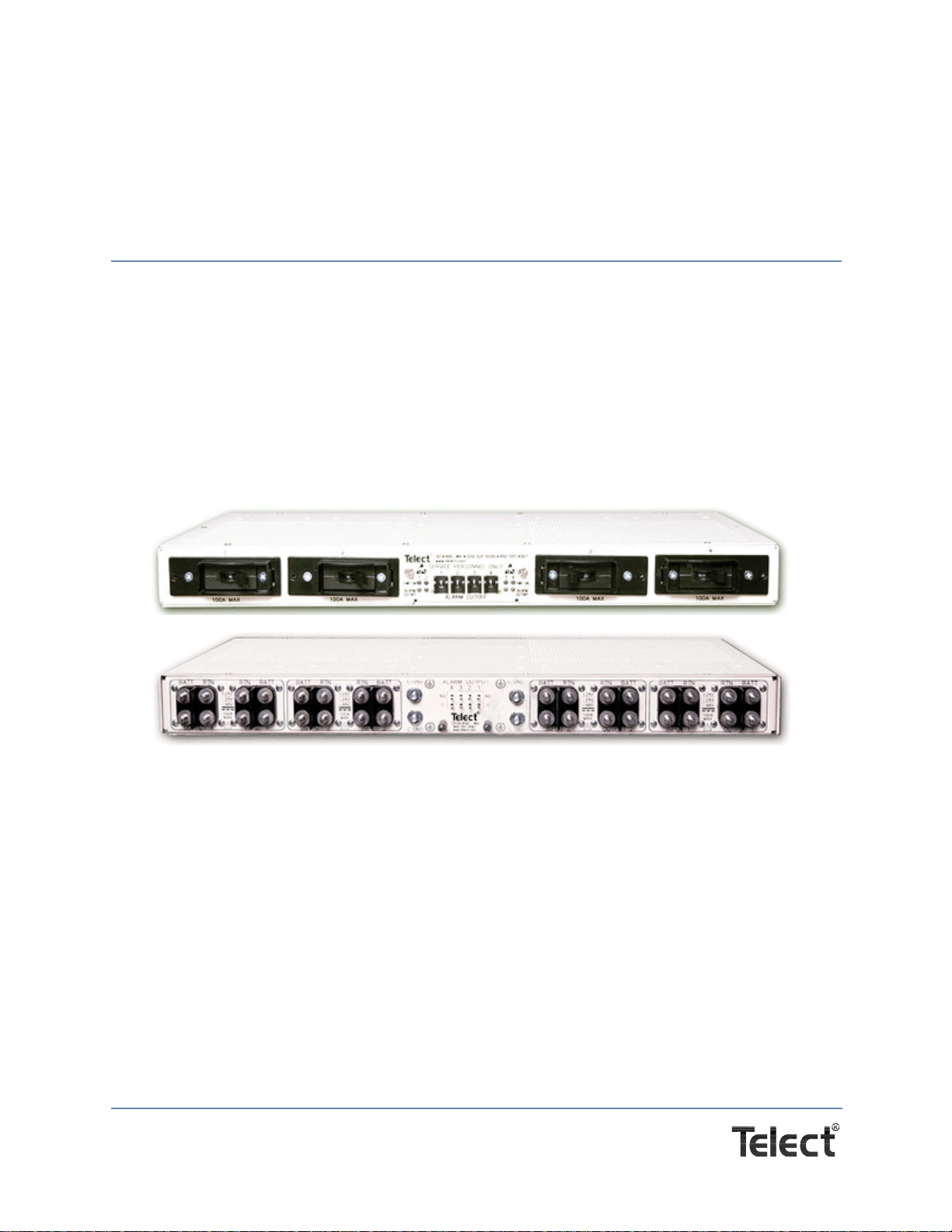
4x100A Demarcation Breaker
Panel With Alarms
Model 009-7000-0104
Installation Guide
1.1 Overview
Telect's 4 x 100A Demarcation Breaker Panel With Alarms provides breaker protection at
equipment interface. The low profile panel includes four breaker positions with blank face plates,
a replaceable alarm card containing power/alarm cut-off LEDs, visual and audio indicator relays,
and rear-access terminals and wirewrap alarm switch contacts. Each breaker has separate
BATT/RTN inputs and outputs.
Hardware is included for either flush or extended mounting in a 19" or 23" relay rack. Visit our
website (www.telect.com) for ordering accessories and replaceable parts: breakers (up to 100A,
each), lugs, ETSI mounting brackets, and more.
Figure 1 - Model 009-7000-0104
(Listed by UL for US and Canada, File No. E139903; NEBS3 Compliant)
1.2 Inspection
Please read these instructions carefully before beginning installation. If you need assistance, call
Technical Support at 1-888-821-4856 (domestic calls), or 509-921-6161 (Option 2), or email us at
Inspect equipment after unpacking and compare it to the packing list.
Immediately report any shipping damage, defects, or missing parts to Telect at 1-800-551-4567.
Keep all documentation that comes with your shipment.
Telect, Inc. • USA +1.509.926.6000 • Mexico +52.33.3836.37.52
www.telect.com • © 2010 Telect, Inc., All Rights Reserved, 118677-4 A0
Page 2
Telect is not liable for shipping damage. If the product is damaged, notify the carrier and call
Telect’s Customer Service Department at 1-800-551-4567 (domestic only) or 1-509-926-6000 for
further recourse.
NOTE: For service or warranty information, please visit telect.com website, or email inquiries to
getinfo@Telect.com and click on the “Support” tab, or phone us at 800-551-4567 (domestic only)
or 509-926-6000.
CAUTION
!
CAUTION! Install this equipment in locations only accessible to qualified persons.
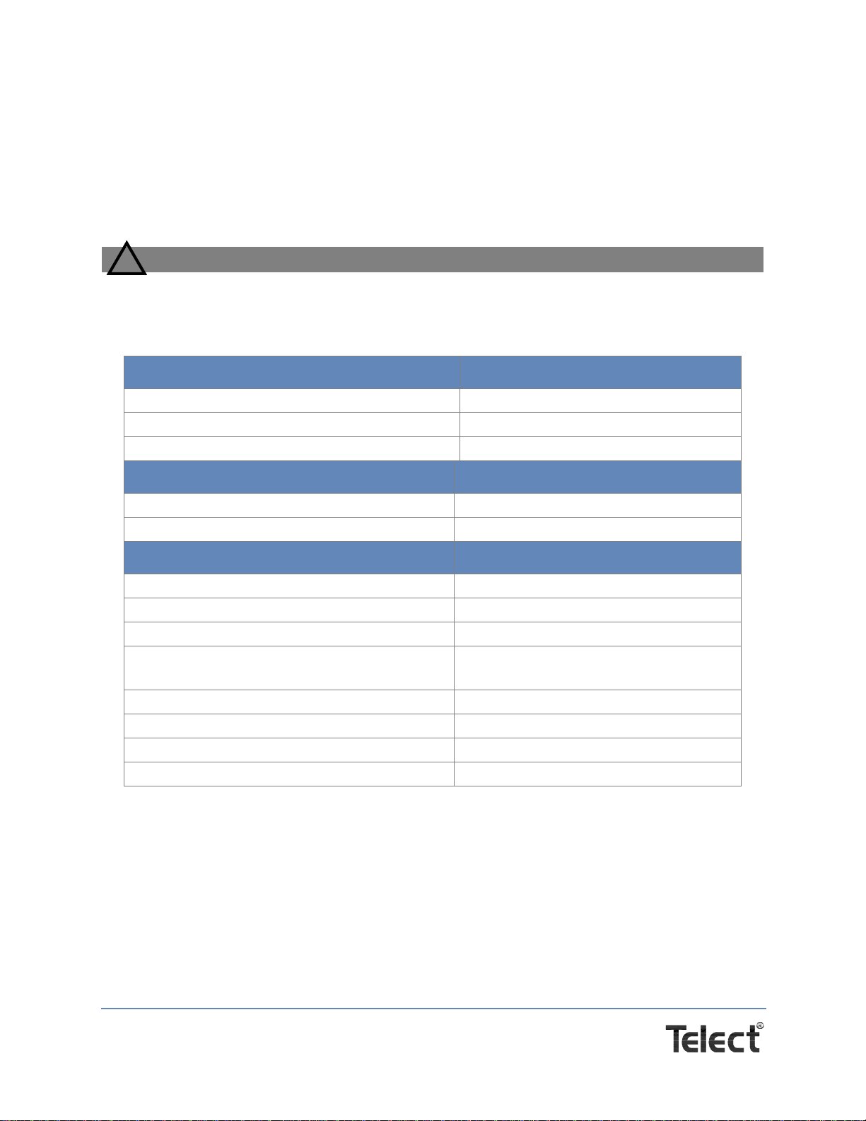
1.3 Specifications
Alarms: Specification:
Alarm Relay Contacts 0.6A @ 60 Vdc
Alarm Card Power Rating 1W
Alarm Wire Size Solid: #26 to #22 AWG
Physical*/Environment: Specification:
Operating Temp Range –10°C (14°F) to 55°C (131°F)
Weight With Packaging ~10 lb (~4½ kg)
Inputs/Outputs: Specification:
Max. Breaker (each) 100A.
Max. Output Load (each) 80A continuous
Max. Total Load Rating 320A continuous
Voltage Range +20 to +28 Vdc
–40 to –60 Vdc
BATT & RTN Wire Size #8 to #2 AWG
Ground Wire Size #10 to #2 AWG (depends on input fuse)
Terminal Studs (Input, Output, and Earth Ground) M5 dual studs on 5/8" centers
Power Dissipation 17W per channel

Telect, Inc. • USA +1.509.926.6000 • Mexico +52.33.3836.37.52
www.telect.com • © 2010 Telect, Inc., All Rights Reserved, 118677-4 A0
Page 3
1.4 Installation
NOTE: Panel brackets are provided for flush or extended
mounting in an EIA or WECO rack.
Procedure steps:
1. If necessary, remove the three screws and reposition/
realign the brackets on the sides of the breaker panel,
as shown in Figure 2.
2. Locate an unused rack position and mount panel using 4
screws and star washers provided, as shown in Figure 3. (It’s
best to mount the panel as high as possible on the rack.)
Tighten the screws to 35 in.-lb (4.29 N•m).
WARNING
!
WARNING! Failure to properly ground this equipment can create hazardous conditions to
installation personnel and to the equipment.
3. Use a UL/NRTL-approved crimping tool to attach a UL/NRTL-approved, 2-hole compression
lug (fit M5 dual studs on 5/8" centers) onto a #10 to #2 AWG ground wire. (Size of ground wire
depends on size of input BATT wires.)
4. Attach opposite end of ground wire to relay rack, per local practices.
Figure 2 - Bracket Orientation
Figure 3 - Rack Mounting

Telect, Inc. • USA +1.509.926.6000 • Mexico +52.33.3836.37.52
www.telect.com • © 2010 Telect, Inc., All Rights Reserved, 118677-4 A0
Page 4
5. If required, lightly coat antioxidant on lug, grounding
terminal, and contacting surface. Connect lug to termi-
nal using KEPS nut from terminal, as shown in Figure
4. Tighten the nut to 20 in.-lb (2.27 N-m).
WARNING
!
WARNING! Before connecting input power cables,
make sure input power to panel is turned off.
NOTE: Input and output wire size for this panel must be
rated for the corresponding breaker/fuse size. The input
wiring to this panel may be a greater size to accommodate
a voltage drop from the primary power source.
NOTE: Always follow operating company guidelines when
connecting input wiring to the primary power source.
6. Make sure the input power is off.
7. For input wiring — wiring used as inputs to this demarcation panel — crimp straight or an-
gled, 2-hole compression lugs (fit M5 dual studs on 5/8" centers) onto #8 to #2 copper wires.
Insulate lug barrels with UL94 V-0 rated heat shrink tubing.
8. Remove the plastic covers from all battery (BATT) and return (RTN) input terminals.
9. Clean the terminals with a nonabrasive, nonmetallic pad.
10. If required, lightly coat antioxidant on lugs and input terminals, and then connect lugs to input
terminals on back of panel, as shown in Figure 5. Tighten the lugs to 20 in.-lb (2.27 N-m).
Anti-oxidant
compound
(If required)
Compression lug
If necessary
remove paint
on sheet metal under lug
(recommended)
Figure 4 - Ground Lug Connection
RTN BATT
Heat Shrink Tubing
Figure 5 - Input Lug Connections
Telect, Inc. • USA +1.509.926.6000 • Mexico +52.33.3836.37.52
www.telect.com • © 2010 Telect, Inc., All Rights Reserved, 118677-4 A0
Page 5
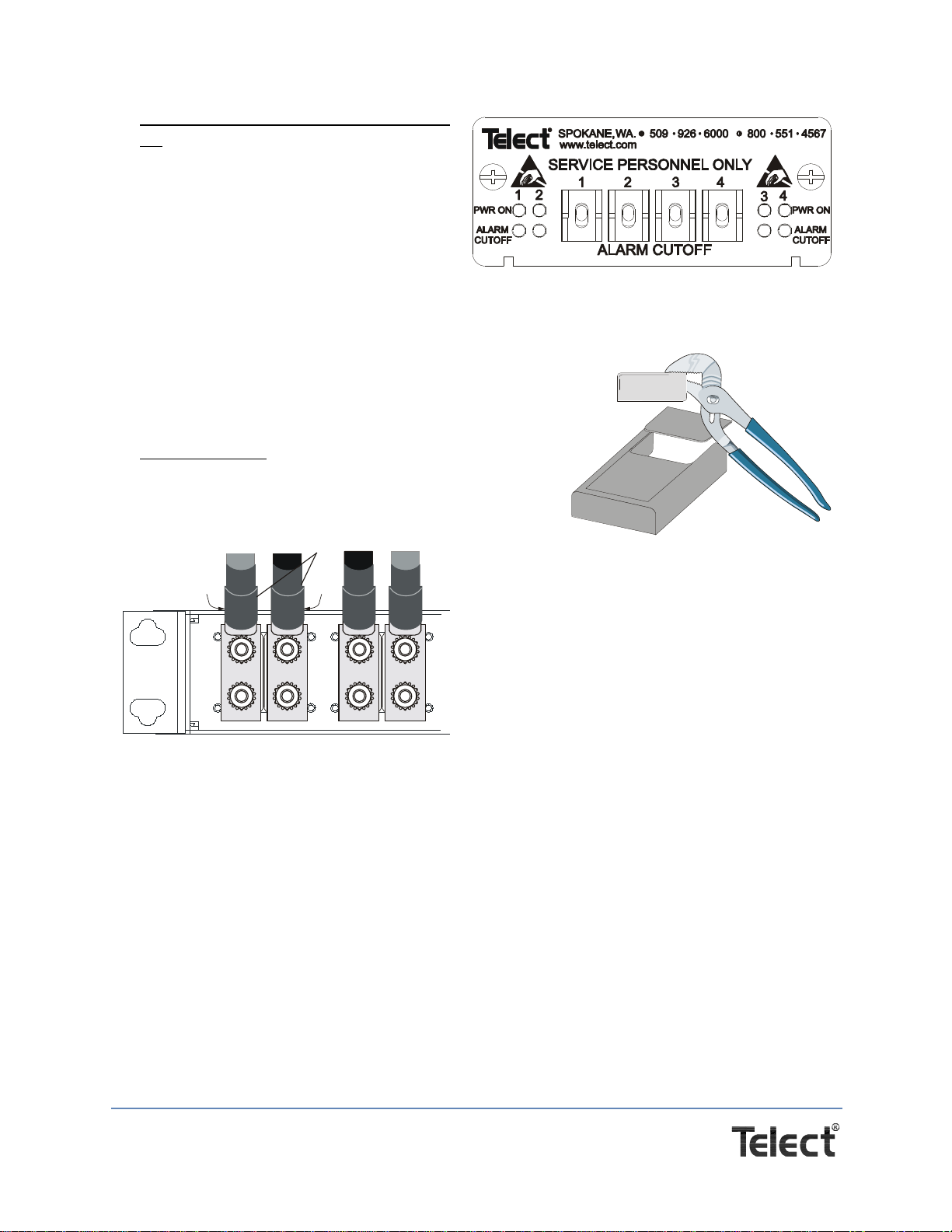
11. Before installing breakers and output wir-
ing, turn power on to verify input power
and indicators:
• Verify input voltage and polarity.
• Whenever power is supplied, expect
corresponding PWR ON LED to light.
See Figure 6.)
12. Reattach plastic covers over input termi-
nals having attached lugs.
The plastic covers are pressed over the terminal studs.
If using angled lugs, break out the scored lip of the
corresponding cover with pliers, as shown in Figure 7.
Remove any sharp edges around the breakout.
13. For output wiring, repeat Steps 7 through 10 for BATT
and RTN outputs (crimp output wires to lugs, clean
output terminals, and attach lugs to output terminals).
Heat shrink lug barrels. See Figure 8.
14. Attach plastic covers over all output terminals.
15. Remove blank face plates at intended breaker postions.
Figure 6 - LEDs & ALARM CUTOFF Switches
on Front Panell
Figure 7 - Removing Break-
Away on Lug Cover
INPUT 4OUTPUT 4
RTN
BATT
Heat Shrink Tubing
Figure 8 - Output Lug Connections
Telect, Inc. • USA +1.509.926.6000 • Mexico +52.33.3836.37.52
www.telect.com • © 2010 Telect, Inc., All Rights Reserved, 118677-4 A0
Page 6
16. Before installing breakers, screw the face
plates to the breakers using two of the
three screws provided with each face
plate, as shown in Figure 9.
CAUTION
!
CAUTION! Do not install breakers with breakers switched on. Doing so may damage
breakers or panel.
Telect recommends that the individual circuit load not exceed 80% of circuit breaker
capacity (for example, 100A breaker x .80 = 80A max. load).
17. With input power on, but with the breaker off (or open), firmly install each breaker in the pan-
el. Use the screw to secure each breaker plate to the panel.
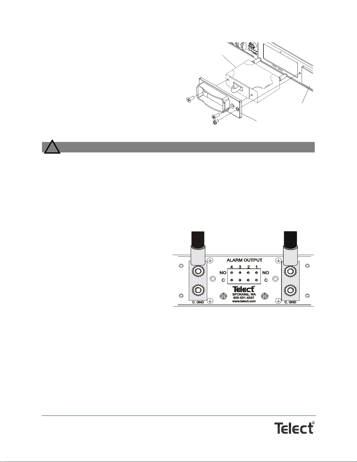
18. Test the Alarm Card.
a. Set all ALARM CUTOFF switches
on the front to the SERVICE (down)
position. With breakers off, check all
pairs of alarm terminals.
(See Figure 10.)
−Expect an open circuit (∞Ω) be-
tween Terminals C and NO.
ALARM CUTOFF LEDs should
be unlit.
b. Set all ALARM CUTOFF switches
on the front of the demarcation panel
to the NORMAL (up) position:
−Expect an open circuit (∞Ω) between Terminals C and NO for any position either with-
out a breaker or with a breaker that is ON.
−Expect continuity (0Ω) between C and NO for all positions containing a breaker that is
OFF (alarm condition). Also, the corresponding ALARM CUTOFF LED (front panel)
should be OFF.
NOTE: Under normal conditions, that is, with the power and circuit breakers on and with the
ALARM CUTOFF in the NORMAL (up) or SERVICE (down) position, expect an open circuit
Telect breaker face plate
Circuit breaker
Blank face plate
Figure 9 - Installing Circuit Breakers
Figure 10 - Alarm Relay Terminals on the Rear
of the Panel

Telect, Inc. • USA +1.509.926.6000 • Mexico +52.33.3836.37.52
www.telect.com • © 2010 Telect, Inc., All Rights Reserved, 118677-4 A0
Page 7
(∞Ω)
between Terminals C and NO on the rear of the demarcation panel. Also, the
corresponding ALARM CUTOFF LEDs should be OFF.
If a breaker trips with its corresponding ALARM CUTOFF switch in the NORMAL (up)
position, expect continuity (0Ω) between Terminals C and NO. Thereafter, if the
corresponding ALARM CUTOFF is switched to SERVICE (down), expect the corresponding
ALARM CUTOFF LED to light with an open circuit (∞Ω) again obtained between
corresponding Terminals C and NO.
19. Wire-wrap alarm pins with solid #26 to #22 AWG.
20. Make sure the output devices — devices fed from the outputs of this demarcation panel —
are off.
21. Switch on each circuit breaker, one at a time, and check the voltage and polarity at the output
terminals and equipment ends. Verify the normal operating conditions outlined in the preced-
ing Note.
This procedure is complete.
Telect, Inc. • USA +1.509.926.6000 • Mexico +52.33.3836.37.52
www.telect.com • © 2010 Telect, Inc., All Rights Reserved, 118677-4 A0
Page 8
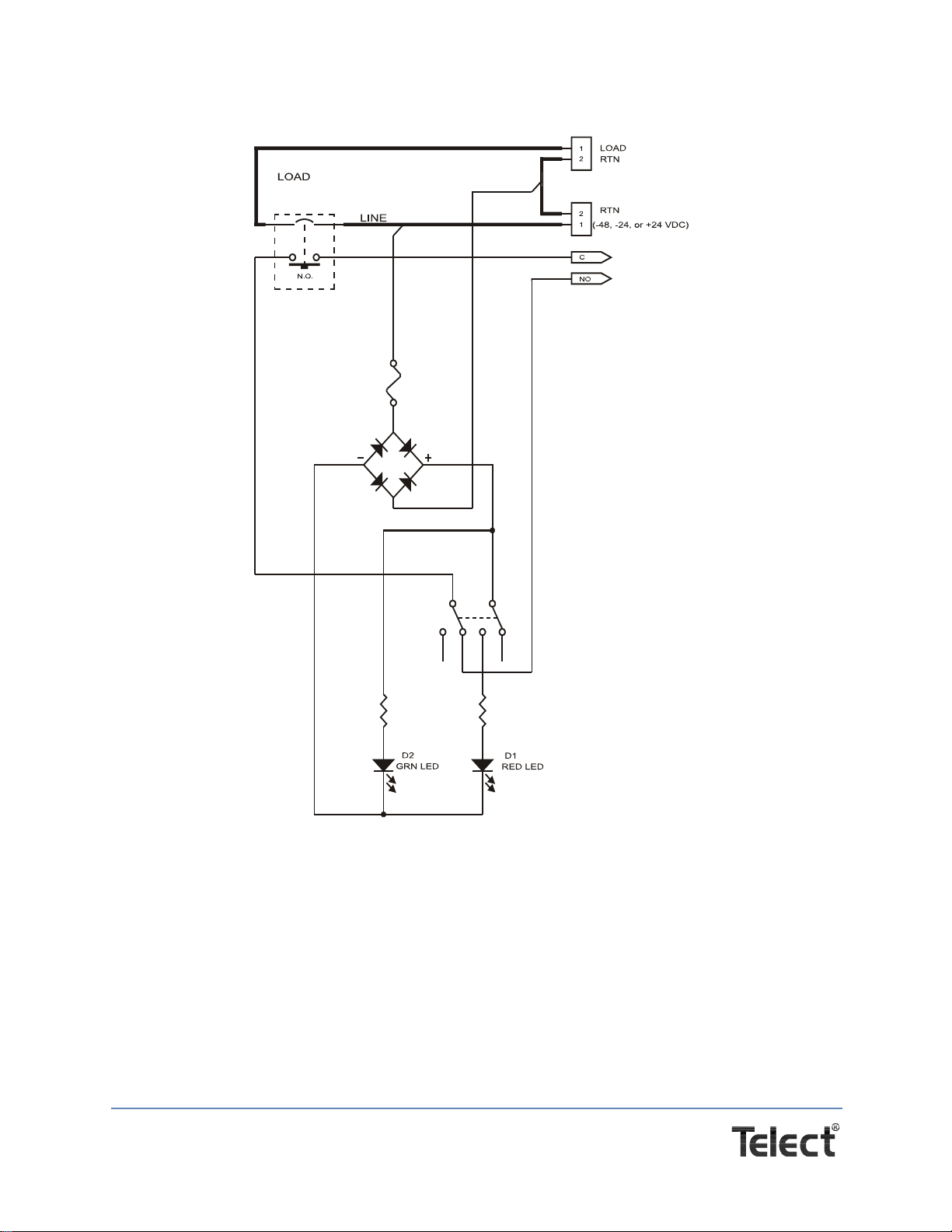
1.5 Schematic (1 of 4 Circuits) & Dimensions
Figure 11 - Schematic 1

Telect, Inc. • USA +1.509.926.6000 • Mexico +52.33.3836.37.52
www.telect.com • © 2010 Telect, Inc., All Rights Reserved, 118677-4 A0
Page 9
Figure 12 - Dimensions
ALARM CUTOFF
PWR ON
ALARM
CUTOFF
PWR ON
ALARM
CUTOFF
112 34
3
24
926509
®
2341
100A MAX 100A MAX 100A MAX100A MAX
551 45676000
OUTPUT 4
BATT BATT BATTBATTRTN RTN RTNRTN
INPUT 4 OUTPUT 3 INPUT 3 INP UT 2
BATT BATT BATTBATTRTN RTN RTNRTN
OUTPUT 2 INPUT 1 OUTPUT 1
!!!!
+24V
–24V
–48V
100A
MAX
+24V
–24V
–48V
100A
MAX
+24V
800
www .telect.com
SPOKANE,WA.
®
SPOKANE, WA
800-551-4567
www.telect.com
ALARM OUTPUT
C. G ND C. G ND
C. GND C. GND
NO NO
C C
4321
SERVICE PERSONNEL ONLY
–24V
–48V
100A
MAX
+24V
–24V
–48V
100A
MAX
5/8 in. Center Spacing
M5 Ground & Input Posts
With 5/8 in. Center Spacing
Notes: 1. Dimensions are in inches (centimeters)
9.00 (22.86)
17.25 (43.82)
REAR VIEW
ROTATED. SHOWN WITHOUT TERMINAL COVERS
TOP VIEW
FRONT VIEW
18.31 (46.51)
19.00 (48.26)
22.31 (56.67)
23.00 (58.42)
1.00 (2.54)
1.25 (3.17)
1.72 (4.37)
(SHOWN WITH CIRCUIT BREAKERS)
2. Circuit breakers are not supplied.
10.21
(25.9)
Blank Face Plates

Telect, Inc. • USA +1.509.926.6000 • Mexico +52.33.3836.37.52
www.telect.com • © 2010 Telect, Inc., All Rights Reserved, 118677-4 A0
Page 10
1.6 Accessories—Long Delay Breakers
Telect assumes no liability from the application or use of these products. Neither does Telect
convey any license under its patent rights or the patent rights of others. This document and the
products described herein are subject to change without notice.
Amperage Telect Part Number
10A 090-0052-0010
20 A 090-0052-0020
30 A 090-0052-0030
40 A 090-0052-0040
50 A 090-0052-0050
60 A 090-0052-0060
70 A 090-0052-0070
80 A 090-0052-0080
90 A 090-0052-0090
100 A 090-0052-0100
Table of contents
Other Telect Circuit Breaker manuals

Popular Circuit Breaker manuals by other brands


Delixi
Delixi NAVIGATOR Series user manual

WEG
WEG ACW400 manual

WEG
WEG VBWC Series Installation,operation and maintenance instruction

GE
GE AM-4.16-250-6C INSTRUCTIONS AND RENEWAL PARTS

Rockwell Automation
Rockwell Automation Allen-Bradley 140U installation instructions

Eaton
Eaton VCP-TL Series Instructions for the Use, Operation and Maintenance


