GE AK-4-75 User manual

MAINTENANCE
MANUAL
(
SUPPLEMENT
)
LOW
-
VOLTAGE
POWER
CIRCUIT
BREAKERS
labl
-
8
b
135
B
Supplement
to
GEK
-
7303
This
manual
when
used
in
conjunction
with
Publication
GEK
-
7303
(
Maintenance
Manual
for
the
AK
-
50
,
75
&
100
frame
breakers
)
provides
maintenance
instructions
on
the
breaker
models
and
trip
devices
tabu
-
lated
below
.
Breaker
Type
&
Mounting
Trip
Device
Type
Frame
Size
(
Amp
)
ECS
SST
Stationary
Drawout
AK
-
4
-
75
,
75
C
AK
-
4
A
-
75
,
75
C
X
3000
AK
-
5
A
-
75
,
75
C
AK
-
5
-
75
,
75
C
X
AK
-
4
A
-
100
X
AK
-
4
-
100
4000
AK
-
5
A
-
100
X
AK
-
5
-
100
*
%
#
m
m
vU
:
»
A
”
I
v
V
AK
-
5
A
-
75
Rear
View
•
'
/
%
GENERAL
W
ELECTRIC
Courtesy of NationalSwitchgear.com

PUSH
TO
RESET
\
SHORT
TIME
«
NST
.
PICKUP
GROUND
r
V
FIG
.
1
.
SST
Programmer
Unit
CONTENTS
3
Introduction
3
Type
SST
Overcurrent
Trip
Device
Components
Trip
Characteristics
Flux
Shift
Trip
Device
Troubleshooting
SST
Test
Set
TAK
-
TS
1
False
Tripping
(
Ground
Fault
)
...
Replacement
of
Current
Sensors
.
Cabling
Diagrams
Ground
Fault
Defeat
Cable
3
6
7
10
10
11
1 1
12
13
14
Type
ECS
Overcurrent
Trip
Device
Components
Trip
Characteristics
Cabling
Diagram
14
15
15
16
ECS
&
SST
Time
-
Current
Curves
2
Courtesy of NationalSwitchgear.com

MAINTENANCE
MANUAL
SUPPLEMENT
LOW
-
VOLTAGE
POWER
CIRCUIT
BREAKERS
TM
TM
TYPES
AK
-
75
/
100
WITH
ECS
AND
SST
TRIP
DEVICES
INTRODUCTION
TYPE
SST
OVERCURRENT
TRIP
DEVICE
The
SST
is
a
solid
-
state
,
direct
-
acting
,
self
-
pow
-
ered
trip
device
system
.
Referring
to
Figures
l
through
8
,
it
comprises
the
following
individual
com
-
ponents
:
Programmer
Unit
—
provides
the
comparison
basis
for
overcurrent
detection
and
delivers
the
energy
necessary
to
trip
the
breaker
.
Contains
the
electronic
circuitry
for
the
various
trip
elements
.
Their
associ
-
ated
pickup
and
time
delay
adjustments
(
set
-
points
)
are
located
on
the
face
plate
.
Depending
on
the
ap
-
plication
,
programmer
units
may
be
equipped
with
various
combinations
of
Long
Time
,
Short
Time
,
In
-
stantaneous
and
Ground
Fault
trip
elements
.
See
Table
1
for
available
ratings
,
settings
and
trip
char
-
acteristics
.
The
data
in
this
supplement
pertain
to
AK
-
75
and
AK
-
100
frame
breakers
equipped
with
type
ECS
and
SST
solid
-
state
trip
devices
.
The
latter
are
not
treated
in
the
primary
maintenance
manual
(
publica
-
tion
GEK
-
7303
)
covering
these
breaker
frame
sizes
.
In
scope
,
this
supplement
supplies
the
essential
descriptive
and
instructional
material
applicable
to
the
new
trip
devices
.
Although
breakers
so
equipped
carry
new
type
designations
(
AK
-
4
/
4
A
and
AK
-
5
/
5
A
)
,
the
basic
breakers
and
their
other
accessory
devices
are
identical
to
those
equipped
with
Power
Sensor
or
EC
trip
devices
.
Accordingly
,
the
general
operational
and
maintenance
information
contained
in
publication
GEK
-
7303
is
equally
relevant
to
ECS
or
SST
equipped
breakers
and
is
not
duplicated
here
.
In
the
event
that
a
programner
set
knob
is
Note
:
left
untightened
,
the
trip
function
reverts
to
operation
at
its
minimum
or
maximum
set
point
value
as
follows
:
Unless
otherwise
noted
,
the
contents
of
this
sup
-
plement
are
to
be
interpreted
as
applicable
to
both
the
AK
-
75
and
AK
-
100
frames
.
Except
for
the
pro
-
grammer
and
'
sensor
differences
noted
below
,
the
hardware
elements
(
e
.
g
.
,
cabling
,
flux
shift
trip
actua
-
tors
and
linkage
)
and
the
test
/
adjustment
procedures
are
identical
.
Pickup
Delay
Trip
Element
Min
.
,
Min
.
Max
.
Max
.
Long
Time
X X
Examples
:
Programmer
units
without
the
Ground
Fault
element
are
identical
;
with
Ground
Fault
,
however
,
the
programmers
have
different
pickup
ranges
.
Sensor
tap
rat
-
ings
also
differ
for
each
frame
.
Short
Time
X
X
Instantaneous
X
Ground
Fault
X
X
These
instructions
do
not
purport
to
cover
all
details
or
variations
in
equipment
nor
to
provide
for
every
possible
contin
-
gency
to
be
met
in
connection
with
installation
,
operation
or
maintenance
.
Should
further
information
be
desired
or
should
particular
problems
arise
which
are
not
covered
sufficiently
for
the
purchaser
’
s
purposes
,
the
matter
should
be
referred
to
the
General
Electric
Company
.
3
Courtesy of NationalSwitchgear.com

n
The
SST
programmer
units
can
be
optionally
equipped
with
trip
indicators
(
targets
)
.
These
are
pop
-
out
,
mechanically
-
resettable
plungers
located
across
the
top
of
the
programmers
front
.
Units
with
a
ground
fault
element
employ
three
(
3
)
targets
:
from
left
to
right
,
the
first
is
for
overload
,
the
second
for
short
circuit
(
actuated
by
the
short
time
and
instan
-
taneous
elements
)
and
the
third
for
ground
fault
.
The
latter
is
omitted
on
units
without
ground
fault
.
0
i
r
i
SOLID
STATE
SWITCH
•
•
FLUX
SHIFT
-
TRIP
COIL
CURRENT
SENSOR
*
"
*
I
TAP
I
I
CHANGER
0
0
-
4
OVERLOAD
Y
I
TARGET
J
LONG
TIME
DELAY
i
TTT
I
T
0
i
LONG
SHORT
TIME
PICKUP
&
DELAY
LOGIC
I
0
’
TIME
Each
target
pops
out
when
its
associated
trip
ele
-
ment
operates
to
trip
the
breaker
.
After
a
trip
,
the
popped
target
must
be
reset
by
hand
.
However
,
ne
-
glecting
to
reset
does
not
affect
normal
operation
of
any
trip
element
or
prevent
the
breaker
from
being
reclosed
.
NEUTRAL
“
OR
”
PICKUP
f
3
(
)
i
I
SHORT
CIRCUIT
TARGET
SL
JL
I
DIFFERENTIAL
TRANSFORMER
_
INSTANTANEOUS
PICKUP
I
J
/
WHEN
\
t
USED
/
GROUND
TARGET
I
GROUND
FAULT
PICKUP
&
DELAY
REGULATED
40
VDC
POWER
SUPPLY
Current
Sensors
—
each
pole
mounts
a
single
sensor
coil
(
CT
)
which
supplies
the
power
and
signal
inputs
necessary
to
operate
the
trip
system
.
Each
sensor
has
four
taps
which
provide
field
adjustment
of
the
trip
device
’
s
continuous
ampere
rating
.
J
I
PROGRAMMER
UNIT
Fig
.
2
.
SST
Block
diagram
The
SST
Ground
Fault
trip
element
operates
on
the
principle
that
the
instantaneous
values
of
current
in
the
three
conductors
(
four
on
4
-
wire
systems
)
add
to
zero
unless
ground
current
exists
.
On
SST
’
s
equipped
with
Ground
Fault
,
the
ground
trip
signal
is
developed
by
connecting
each
phase
sensor
in
se
-
ries
with
a
companion
primary
winding
on
a
ground
differential
transformer
mounted
in
the
programmer
unit
.
Its
secondary
output
is
zero
as
long
as
there
is
no
ground
current
.
When
used
,
the
neutral
sensor
(
fig
.
6
)
is
separately
mounted
in
the
bus
or
cable
compartment
of
the
switchgear
.
In
drawout
construction
,
its
output
is
au
-
tomatically
connected
to
the
breaker
via
secondary
disconnect
blocks
.
See
Figs
.
4
,
5
and
15
.
Application
of
the
Ground
Fault
element
to
4
-
wire
systems
with
neutral
grounded
at
the
transformer
re
-
quires
an
additional
,
separately
mounted
sensor
(
Fig
.
6
)
inserted
in
the
neutral
conductor
;
its
secondary
is
connected
to
a
fourth
primary
winding
on
the
ground
differential
transformer
.
See
Fig
.
15
.
This
“
fourth
-
wire
”
neutral
sensor
is
an
electrical
duplicate
of
the
phase
sensor
,
including
taps
.
Therefore
,
when
taps
are
changed
on
the
phase
sensors
,
those
on
the
neu
-
tral
sensor
must
be
correspondingly
positioned
.
Flux
Shift
Trip
Device
—
a
low
-
energy
,
elec
-
tromagnetic
device
which
,
upon
receipt
of
a
trip
sig
-
nal
from
the
programmer
unit
,
trips
the
breaker
by
actuating
the
trip
shaft
.
See
Fig
.
8
.
COMPONENT
LOCATION
All
components
except
the
neutral
sensor
are
mounted
on
the
circuit
breaker
.
The
phase
sensors
are
mounted
around
the
lower
studs
at
the
rear
of
the
breaker
(
see
Fig
.
4
)
.
The
programmer
unit
and
the
flux
shift
trip
device
are
mounted
on
the
breaker
’
s
front
frame
.
These
components
are
interconnected
by
wiring
harness
and
disconnect
plugs
as
shown
on
the
cabling
diagrams
(
Figs
.
13
and
14
)
.
/
Fig
.
3
.
SST
phase
sensor
with
tap
board
4
Courtesy of NationalSwitchgear.com

Fig
.
7
.
AK
-
5
A
-
100
(
front
view
)
TABLE
1
—
SST
TRIP
CHARACTERISTICS
SST
PROGRAMMER
ADJUSTMENT
RANGE
(
Set
Points
)
Sensor
Ampere
Taps
Long
Time
Short
Time
Ground
Fault
Frame
Size
(
Amperes
)
Instantaneous
Pickup
Breaker
Type
Pickup
(
=
L
)
Time
Delay
Band
®
(
Seconds
)
Pickup
Time
Delay
Band
®
(
Seconds
)
Pickup
©
Time
Delay
Band
®
(
Seconds
)
©
©
©
©
(
X
)
Multiple
Multiple
Multiple
Multiple
of
X
of
L
of
L
of
X
1200
,
1600
,
2000
,
3000
AK
-
75
3000
Maximum
3
,
4
,
5
,
6
,
8
,
10
(
L
)
-
or
-
1.75
,
2
,
2.25
,
2.5
,
3
*
4
(
L
)
Maximum
0.35
Intermed
.
0.21
Minimum
0.095
.
20
,
.
22
,
.
25
.
30
,
.
35
,
.
4
(
X
)
Maximum
0.30
Intermed
.
0.165
Minimum
0.065
22
.
6
,
.
7
,
.
8
,
.
9
,
1.0
,
1.1
(
X
)
Intermed
.
4
,
5
,
6
,
8
,
10
,
12
(
L
)
/
10
4000
1600
,
2000
,
3000
,
4000
AK
-
100
Minimum
.
18
,
.
20
,
.
22
,
.
25
,
.
27
,
.
30
(
X
)
4
©
X
=
Sensor
ampere
tap
=
trip
rating
©
Pickup
tolerance
is
±
10
%
©
Time
delay
at
lower
limit
of
band
@
6
L
.
®
Time
delay
at
lower
limit
of
band
.
V
(
See
pages
17
and
19
for
applicable
time
-
current
curves
)
6
Courtesy of NationalSwitchgear.com

Flux
shift
trip
device
Fig
.
8
.
AK
-
5
A
-
75
(
front
view
)
“
reset
”
position
.
Loosen
the
jam
nut
,
rotate
the
ad
-
juster
end
until
the
proper
gap
is
attained
,
then
re
-
tighten
the
jam
nut
.
While
operating
the
breaker
,
insure
that
the
actua
-
tor
bracket
does
not
interfere
with
the
buffer
stud
.
Adjust
if
necessary
.
FLUX
SHIFT
TRIP
DEVICE
The
mounting
arrangement
of
this
component
is
il
-
lustrated
in
Figures
8
,
9
and
10
.
An
electromagnetic
actuator
mounted
to
the
left
side
of
the
front
frame
is
coupled
to
the
breaker
’
s
trip
shaft
via
a
trip
rod
driven
by
the
actuator
arm
.
The
actuator
is
a
sole
-
noid
whose
armature
is
spring
-
loaded
and
held
in
its
normal
(
reset
)
position
by
a
permanent
magnet
.
In
this
state
the
spring
is
in
tension
.
The
actuator
is
a
sealed
,
factory
-
set
device
and
re
-
quires
no
maintenance
or
field
adjustment
.
In
case
of
malfunction
,
the
complete
actuator
unit
should
be
re
-
placed
.
When
making
the
electrical
connection
to
the
replacement
unit
,
it
is
recommended
that
the
breaker
harness
be
cut
at
some
convenient
point
and
the
new
actuator
leads
solder
-
spliced
thereto
.
An
alternate
method
is
to
untie
the
breaker
harness
and
remove
the
old
actuator
leads
directly
from
the
female
AMP
connector
on
the
end
of
the
breaker
harness
.
How
-
ever
,
AMP
extraction
tool
Cat
.
No
.
305183
is
re
-
quired
for
this
method
.
As
long
as
the
actuator
remains
in
the
reset
posi
-
tion
,
the
breaker
can
be
closed
and
opened
normally
at
will
.
However
,
when
a
closed
breaker
receives
a
trip
signal
from
the
programmer
unit
,
the
actuator
is
energized
and
its
solenoid
flux
opposes
the
magnet
,
allowing
the
spring
to
release
the
armature
;
this
drives
the
trip
rod
against
the
trip
shaft
paddle
,
trip
-
ping
the
breaker
.
As
the
breaker
opens
,
the
actuator
arm
is
returned
to
its
normal
(
reset
)
position
via
linkage
driven
by
a
bracket
attached
to
the
breaker
’
s
crossbar
.
The
per
-
manent
magnet
again
holds
the
armature
captive
in
readiness
for
the
next
trip
signal
.
See
Fig
.
9
.
CAUTION
:
IN
THE
EVENT
THAT
THE
SST
TRIP
DEVICE
MUST
BE
RENDERED
IN
-
OPERATIVE
TO
ALLOW
THE
BREAKER
TO
CARRY
CURRENT
WITHOUT
BENEFIT
OF
OVERCURRENT
PROTECTION
,
THE
RECOMMENDED
METHOD
IS
TO
SHORTEN
THE
TRIP
ROD
BY
TURNING
ITS
ADJUSTER
END
FULLY
CLOCKWISE
.
THIS
PREVENTS
ACTUATION
OF
THE
TRIP
SHAFT
PADDLE
.
The
trip
device
requires
one
basic
adjustment
—
the
trip
rod
length
.
As
shown
in
Fig
.
11
,
the
clearance
between
the
trip
rod
end
and
the
trip
shaft
paddle
is
gaged
by
a
.
093
"
dia
.
rod
.
To
adjust
,
open
the
breaker
and
restore
the
breaker
mechanism
to
its
7
Courtesy of NationalSwitchgear.com

CROSSBAR
(
BKR
.
OPEN
)
/
ACTUATOR
BRACKET
BUFFER
STUD
POSITION
O
/
T
?
TRIP
PADDLE
IN
“
MECHANISM
RESET
’’
POSITION
//
/
JAM
<
9
p
NUT
A
(
B
/
/
/
/
/
/
/
.
093
"
DIA
.
TRIP
ROD
IN
“
RESET
POSITION
ROD
i
J
ADJUSTER
END
Fig
.
11
.
Flux
shift
trip
device
adjustments
SIDE
VIEW
1
.
Trip
rod
length
:
Adjust
gap
to
0.093
"
±
0.015
"
using
0.093
"
diam
.
rod
as
shown
.
2
.
Actuator
bracket
:
As
the
crossbar
travels
between
the
breaker
closed
’’
and
“
breaker
open
”
positions
,
the
tang
of
the
actuator
bracket
must
clear
the
buffer
stud
.
If
in
-
sufficient
clearance
exists
,
loosen
it
’
s
two
mounting
screws
and
rotate
the
bracket
clockwise
to
take
up
mounting
hole
slack
.
Retighten
screws
.
(
i
9
Courtesy of NationalSwitchgear.com

a
.
testing
two
poles
of
the
breaker
in
se
-
nes
or
,
b
.
Using
the
Ground
Fault
Defeat
Cable
as
shown
in
Fig
.
16
.
This
special
test
cable
energizes
all
the
primary
windings
of
the
differential
transformer
in
a
self
-
cancell
-
ing
,
series
-
parallel
connection
so
that
its
secondary
output
is
always
zero
.
TROUBLESHOOTING
When
malfunctioning
is
suspected
,
tne
first
step
in
troubleshooting
is
to
examine
the
circuit
breaker
and
its
power
system
for
abnormal
conditions
such
as
:
a
.
Breaker
tripping
in
proper
response
to
over
-
currents
or
incipient
ground
faults
.
b
.
Breaker
remaining
in
a
trip
-
free
state
due
to
mechanical
interference
along
its
trip
shaft
.
c
.
Inadvertent
shunt
trip
activations
.
Test
the
components
of
the
SST
system
using
portable
Test
Set
type
TAK
-
TS
1
(
Fig
.
12
)
.
The
applicable
test
procedures
are
detailed
in
In
-
struction
Book
GEK
-
64454
and
are
summarized
below
.
2
.
WARNING
:
DO
NOT
CHANGE
TAPS
ON
THE
CURRENT
SENSORS
OR
ADJUST
THE
PROGRAMMER
UNIT
SET
KNOBS
WHILE
THE
BREAKER
IS
CARRYING
CURRENT
.
USING
THE
SST
TEST
SET
Once
it
has
been
established
that
the
circuit
breaker
can
be
opened
and
closed
normally
from
the
test
position
,
attention
can
be
directed
to
the
trip
de
-
vice
proper
.
Testing
is
performed
by
either
of
two
methods
:
The
TAK
-
TS
1
Test
Set
is
a
portable
instrument
designed
for
field
-
checking
the
time
-
current
charac
-
teristics
and
pickup
calibration
of
the
SST
’
s
various
trip
elements
.
It
can
verify
the
ability
of
the
Flux
-
Shift
Trip
Device
to
trip
the
breaker
and
,
in
addi
-
tion
,
includes
means
for
continuity
checking
the
phase
sensors
.
1
.
Conduct
high
-
current
,
single
phase
tests
on
the
breaker
using
a
high
current
-
low
voltage
test
set
.
WARNING
:
BEFORE
CONNECTING
THE
TEST
SET
TO
THE
BREAKER
TRIP
DEVICE
SYSTEM
,
ENSURE
THAT
THE
CIRCUIT
BREAKER
IS
COMPLETELY
DISCON
-
NECTED
FROM
ITS
POWER
SOURCE
.
ON
DRAWOUT
EQUIPMENT
,
RACK
THE
BREAKER
TO
ITS
DISCONNECTED
POSI
-
TION
.
VERIFY
THAT
THE
BREAKER
IS
TRIPPED
.
t
NOTE
:
For
these
single
-
phase
tests
,
spe
-
cial
connections
must
be
employed
for
SST
breakers
equipped
with
Ground
Fault
.
Any
single
-
phase
input
to
the
ground
differential
transformer
will
gener
-
ate
an
unwanted
"
ground
fault
”
output
signal
which
will
trip
the
breaker
.
This
can
be
nullified
either
by
:
/
Fig
.
12
.
SST
/
ECS
test
set
,
CAT
.
NO
.
TAK
-
TS
1
10
Courtesy of NationalSwitchgear.com

If
nuisance
tripping
is
encountered
on
any
breaker
whose
SST
components
have
previously
demon
-
strated
satisfactory
performance
via
the
TAK
-
TS
1
Test
Set
,
the
sensors
and
their
connections
should
be
closely
scrutinized
.
After
disconnecting
the
breaker
from
all
power
sources
,
Either
of
two
test
modes
may
be
employed
:
“
A
"
—
Programmer
Unit
Only
.
These
tests
are
con
-
ducted
with
the
programmer
unit
disconnected
from
the
breaker
.
During
test
,
the
unit
can
remain
at
-
tached
to
the
breaker
or
may
be
completely
removed
from
it
.
a
.
Check
that
all
phase
sensors
are
the
same
type
(
ampere
range
)
.
b
.
Insure
that
the
tap
settings
on
all
3
phase
sen
-
sors
are
identical
.
c
.
Verify
that
the
harness
connections
to
the
sen
-
sors
meet
the
polarity
constraints
indicated
by
the
cabling
diagram
,
i
.
e
.
,
white
wire
to
COM
-
MON
,
black
wire
to
TAP
.
d
.
On
Ground
Fault
breakers
serving
4
-
wire
loads
,
check
that
the
neutral
sensor
is
properly
connected
(
see
cabling
diagram
Fig
.
15
)
.
In
particular
,
1
.
Verify
that
the
neutral
sensor
has
the
same
rating
and
tap
setting
as
the
phase
sensors
.
2
.
Check
continuity
between
the
neutral
sensor
and
its
equipment
-
mounted
secondary
dis
-
connect
block
.
Also
check
for
continuity
from
the
breaker
-
mounted
neutral
secondary
disconnect
block
through
the
female
harness
connector
(
terminals
L
and
N
)
.
3
.
If
the
breaker
’
s
lower
studs
connect
to
the
supply
source
,
then
the
neutral
sensor
must
have
its
“
LOAD
”
end
connected
to
the
source
.
4
.
Insure
that
the
neutral
conductor
is
carrying
only
that
neutral
current
associated
with
the
breaker
’
s
load
current
(
neutral
not
shared
with
other
loads
)
.
e
.
If
the
preceding
steps
fail
to
identify
the
prob
-
lem
,
then
the
sensor
resistances
should
be
mea
-
sured
.
Since
the
phase
and
neutral
sensors
are
electrically
identical
,
their
tap
-
to
-
tap
resistances
should
closely
agree
.
CAUTION
:
NEVER
DISENGAGE
THE
HARNESS
CONNECTOR
FROM
THE
PROGRAMMER
UNIT
ON
A
BREAKER
THAT
IS
ENERGIZED
AND
CARRYING
LOAD
CURRENT
.
THIS
WILL
OPEN
-
CUR
-
CUIT
THE
CURRENT
SENSORS
,
ALLOW
-
ING
DANGEROUS
AND
DAMAGING
VOLTAGES
TO
DEVELOP
.
Test
scope
:
1
.
Verify
the
time
-
current
characteristics
and
pickup
calibration
of
the
various
trip
elements
.
2
.
Verify
operation
of
the
SST
target
indicators
on
programmer
units
so
equipped
.
“
B
”
—
Complete
Trip
Device
System
.
For
these
tests
,
the
programmer
unit
must
be
mounted
on
the
breaker
and
connected
to
its
wiring
harness
.
Test
scope
:
1
.
All
“
A
”
tests
previously
described
,
plus
provi
-
sion
for
optionally
switching
the
programmer
’
s
out
-
put
to
activate
the
Flux
-
Shift
Trip
Device
and
verify
its
operation
by
physically
tripping
the
breaker
.
2
.
Check
phase
sensor
continuity
.
In
the
event
that
any
component
of
the
SST
sys
-
tem
does
not
perform
within
the
limits
prescribed
in
test
instructions
GEK
-
64454
,
it
should
be
replaced
.
FALSE
TRIPPING
-
BREAKERS
EQUIPPED
WITH
GROUND
FAULT
When
nuisance
tripping
occurs
on
breakers
equipped
with
the
Ground
Fault
trip
element
,
a
probable
cause
is
the
existence
of
a
false
“
ground
”
signal
.
As
indicated
by
the
cabling
diagram
of
Fig
.
14
,
each
phase
sensor
is
connected
in
series
with
a
primary
winding
on
the
Ground
Fault
differential
transformer
.
Under
no
-
fault
conditions
on
3
-
wire
load
circuits
,
the
currents
in
these
three
windings
add
to
zero
and
no
ground
signal
is
developed
.
This
current
sum
will
be
zero
only
if
all
three
sensors
have
the
same
electrical
characteristics
.
If
one
sen
-
sor
differs
from
the
others
(
i
.
e
.
,
different
rating
or
wrong
tap
setting
)
,
the
differential
transformer
can
produce
output
sufficient
to
trip
the
breaker
.
Sim
-
ilarly
,
discontinuity
between
any
sensor
and
the
pro
-
grammer
unit
can
cause
a
false
trip
signal
.
REPLACEMENT
OF
CURRENT
SENSORS
Phase
sensors
are
removed
as
follows
(
see
Fig
.
4
)
:
1
.
From
front
of
breaker
,
disconnect
the
harness
wiring
from
the
sensor
tap
board
.
2
.
From
rear
of
breaker
,
unbolt
the
tap
board
;
loosen
and
remove
the
stud
connector
;
the
sensor
and
tap
board
can
now
be
removed
as
a
unit
.
3
.
Reassemble
in
reverse
order
,
taking
care
to
al
-
ign
projections
on
rear
of
sensor
with
notches
in
po
-
sitioning
ring
mounted
on
stud
.
11
Courtesy of NationalSwitchgear.com

<
?
A
<
j
>
B
<
|
»
C
PROGRAMMER
UNIT
BREAKER
_
^
^
BACK
FRAME
|
JT
F
H
>
=
o
=
>
=
o
=
>
=
r
FLUX
SHIFT
TRIP
DEVICE
B
RED
(
48
V
.
dc
)
(
TO
SCR
ANODE
)
<
>
-
<
BLACK
o
-
-
<
9
E
LEFT
POLE
CURRENT
SENSOR
COM
WHITE
o
-
-
<
A
I
C
BLACK
o
-
-
<
I
TAP
WHITE
A
o
-
<
\
lh
D
F
BLACK
I
WHITE
B
o
-
-
<
H
K
BLACK
o
~
“
<
I
C
7
\
/
\/
\
/
TYT
HARNESS
CONNECTOR
(
AMP
201298
-
1
)
PROGRAMMER
CONNECTOR
(
AMP
201297
-
1
)
LOAD
Fig
.
13
.
Cabling
Diagram
-
SST
without
Ground
Fault
$
A
$
B
<
J
>
C
PROGRAMMER
UNIT
AAA
BREAKER
_
,
BACK
FRAME
|
T
[
1
1
)
=
=
oA
=
oAr
FLUX
SHIFT
TRIP
DEVICE
B
RED
(
48
V
.
dc
)
(
TO
SCR
ANODE
)
O
-
-
<
BLACK
o
-
-
<
I
E
LEFT
POLE
CURRENT
SENSOR
COM
WHITE
o
-
-
<
A
I
3
c
BLACK
TAP
WHITE
A
o
-
-
<
D
3
BLACK
I
WHITE
B
H
3
K
BLACK
c
L
7
o
\
/
\
/
\
/
TTY
HARNESS
CONNECTOR
^
(
AMP
201298
-
1
)
N
o
V
/
LOAD
PROGRAMMER
CONNECTOR
(
AMP
201297
-
1
)
with
Ground
Fault
on
3
-
wire
load
.
Fig
.
14
.
Cabling
Diagram
-
SST
12
Courtesy of NationalSwitchgear.com

4
>
A
6
B
<
i
>
c
PROGRAMMER
UNIT
&
A
A
T
“
frt
.
.
FLUX
SHIFT
TRIP
DEVICE
BREAKER
BACK
FRAME
|
B
RED
I
(
48
V
.
dc
)
(
TO
SCR
ANODE
)
o
-
^
<
BLACK
o
-
-
<
I
E
I
LEFT
POLE
CURRENT
SENSOR
|
COM
WHITE
A
I
I
3
c
BLACK
NEUTRAL
I
TAP
WHITE
I
i
A
o
-
<
\
l h
D
I
3
F
BLACK
NEUTRAL
I
SENSOR
DISCONNECT
I
o
<
^
“
-
O
I
WHITE
B
o
-
<
I
H
-
-
I
3
I
K
BLACK
/
/
LINE
I
C
/
COM
WHITE
o
-
»
-
o
/
o
—
-
o
N
BLACK
o
^
C
<
-
-
o
TAP
IN
I
LOAD
|
\
/
\
/
\
/
TTT
T
HARNESS
CONNECTOR
(
AMP
201298
-
1
)
PROGRAMMER
CONNECTOR
(
AMP
201297
-
1
)
i
EQUIPMENT
—
MOUNTED
NEUTRAL
SENSOR
4
-
WIRE
LOAD
Fig
.
15
.
Cabling
Diagram
-
SST
with
Ground
Fault
on
4
-
wire
load
BREAKER
HARNESS
CONNECTOR
PROGRAMMER
UNIT
I
GROUND
FAULT
DEFEAT
CABLE
CAT
.
NO
.
TGFD
1
r
~
i
i
—
i
OH
<
<
—
i
r
B
i
o
7 7
CURRENT
SENSORS
V
A
£
<
t
>
B
£
<
t
>
cF
<
4
<
>
I
a
*
0
<<
—
|
—
0
—
I
—
•
<
<
—
I
—
o
—
l
—
<
<
—
!
—
o
—
I
—
<<
4
-
oJ
-
3
I
I I
Any
SST
Programmer
Unit
with
Ground
Fault
Element
C
c
o
—
j
—
<
<
n
D
°
o
<
4
o
3
a
F
!
H
O
—
j
—
<
<
0
-
|
—
<
<
:
<
<
:
o
3
I
K
I
r
“
»
o h
o
—
|
—
<
4
o
-
j
—
<
4
o
-
H
—
<
4
o
-
4
—
<
4
L
_
°
T
^
<
4
-
r
°
-
|
I
3
i
N
I
NEUTRAL
SENSOR
|
DISCONNECT
1
M
M
O
|
w
o
I
So
u
cF
—
<
<
-
4
-
o
I
J
L
.
L
_
J
I
MALE
FEMALE
END
END
Fig
.
16
.
Cabling
diagram
with
Ground
Fault
Defeat
Cable
inserted
be
-
tween
breaker
harness
and
SST
Programmer
Unit
—
for
use
during
single
-
phase
,
high
current
—
low
voltage
testing
.
i
;
Courtesy of NationalSwitchgear.com

TYPE
ECS
OVERCURRENT
TRIP
DEVICE
The
ECS
is
a
solid
-
state
,
direct
-
acting
,
self
-
pow
-
ered
trip
device
system
that
essentially
duplicates
SST
except
for
the
following
:
1
.
Programmer
units
(
Fig
.
17
)
are
limited
to
com
-
binations
of
Long
Time
,
Short
Time
and
In
-
stantaneous
trip
elements
only
.
The
Ground
Fault
element
is
not
available
.
2
.
Phase
sensors
(
Fig
.
18
)
are
not
tapped
.
As
listed
in
Table
2
,
each
sensor
has
only
a
single
ampere
rating
.
A
different
sensor
is
available
for
each
of
the
tabulated
ampere
rat
-
ings
,
which
span
the
same
range
as
SST
.
3
.
There
being
no
Ground
Fault
function
,
neutral
sensors
are
not
required
.
In
all
other
respects
the
ECS
trip
device
system
operates
and
can
be
treated
identically
to
SST
.
This
includes
circuitry
,
size
,
construction
,
component
lo
-
cation
,
programmer
unit
set
points
,
performance
characteristics
,
operating
range
,
quality
,
reliability
and
the
flux
shift
trip
device
.
Use
the
same
trouble
-
shooting
and
test
procedures
for
single
-
phase
,
high
current
-
low
voltage
tests
or
those
employing
the
TAK
-
TS
1
Test
Set
.
The
Ground
Fault
test
proce
-
dures
,
of
course
,
do
not
apply
.
Fig
.
17
.
ECS
Programmer
Unit
0
r
"
FLUX
SHIFT
SOLID
STATE
SWITCH
I
TRIP
I
COIL
I
OVERLOAD
TARGET
I
PROGRAMMER
UNIT
I
CURRENT
SENSOR
GJI
>
7
-
'
SSr
-
LONG
TIME
—
PICKUP
LONG
TIME
DELAY
*
I
SHORT
TIME
PICKUP
AND
DELAY
i
INSTANTANEOUS
PICKUP
.
SHORT
CIRCUIT
TARGET
REGULATED
48
VDC
POWER
SUPPLY
J
/
•
8
000
L
Fig
.
19
.
ECS
Block
diagram
.
Fig
.
18
.
ECS
phase
sensor
14
Courtesy of NationalSwitchgear.com

QA
4
>
B
<
J
>
C
PROGRAMMER
UNIT
AAA
FLUX
SHIFT
TRIP
DEVICE
BREAKER
_
£
BACK
FRAME
|
B
RED
(
48
V
.
dc
)
(
TO
SCR
ANODE
)
o
-
<
>
=
cr
>
=
d
BLACK
o
-
-
<
E
LEFT
POLE
CURRENT
SENSOR
'
I
v
WHITE
O
-
-
<
K
A
C
BLACK
o
-
K
I
WHITE
A
I
=
D
F
BLACK
o
-
-
<
I
WHITE
B
o
-
-
<
(
[
H
K
BLACK
i
I
I
\
l
_
_
_
N
/
\
/
\
/
TTT
HARNESS
CONNECTOR
(
AMP
201298
-
1
)
PROGRAMMER
CONNECTOR
(
AMP
201297
-
1
)
LOAD
Fig
.
20
.
Cabling
diagram
for
ECS
Trip
Device
TABLE
2
—
ECS
TRIP
CHARACTERISTICS
ECS
PROGRAMMER
ADJUSTMENT
RANGE
(
Set
Points
)
Sensor
Ampere
Rating
Long
Time
Short
Time
Frame
Size
(
Amperes
)
Breaker
Type
Instantaneous
Pickup
Pickup
(
=
L
)
Pickup
Time
Delay
Band
®
(
Seconds
)
Time
Delay
Band
®
(
Seconds
)
©
©
©
(
X
)
Multiple
of
X
Multiple Multiple
of
L
of
L
AK
-
75
3000
1200
,
1600
,
2000
,
3000
Maximum
3
,
4
,
5
,
6
,
8
,
10
(
L
)
-
or
-
1.75
,
2
,
2.25
,
2.5
,
3
,
4
(
L
)
Maximum
0.35
Intermed
.
0.21
Minimum
0.095
22
.
6
,
.
7
,
.
8
,
.
9
,
1.0
,
1.1
(
X
)
Intermed
.
4
,
5
,
6
,
8
,
10
,
12
(
L
)
10
AK
-
100
Minimum
4000
1600
,
2000
,
3000
,
4000
4
®
X
=
Sensor
rating
=
trip
rating
®
Pickup
tolerance
is
±
10
%
®
Time
delay
at
lower
limit
of
band
@
6
L
.
®
Time
delay
at
lower
limit
of
band
.
(
See
page
16
for
time
-
current
curves
)
15
Courtesy of NationalSwitchgear.com

H
MULTIPLES
OF
LONG
-
TIME
PICKUP
(
L
)
i
i
ii
m u
2
III
I
*
111
g
3
4
5
«
7
I
•
10
30
40
50 00
70
OOM
^
A
A
.
7
A
.
1000
II
700
700
iig
000
900
!
:
S
400
/
&
200
200
Long
-
time
Delay
Bands
100
100
*
00
oo
5
*
00
00
70
70
00
i
/
i
50
t
:
o
.
Maximum
Total
Clearing
Time
40
X
id
L
ut
30
%
z
&
&
U
4
Minimum
Total
,
Clearing
Time
i
"
20
S
vs
v
0
jfe
s
10
10
*
9
s
sS
0
7
%
V
S
*
s
S
5
A
s
in
-
V
4
7
v
z
*
s
3
7
s
3
LI
I
/
2
>
7
(
S
High
-
range
Short
-
time
Pickup
Points
,
Low
-
range
Short
-
time
Pickup
Points
s
m
7
m
IA
s
M
z
8
L
1
7
3
lot
]
.
0
0
7
.
7
.
0
N
7
n
A
o
-
-
-
o
V
*
•
Maximum
.
4
m
O
.
3
7
Short
-
time
Delay
Bands
p
Intermediate
S
?
J
M
-
2
s
/
M
Q
N
.
5
Minimum
s
S
v
-
J
u
\
ui
.
1
u
>
00
z
.
00
—
.
07
W
.
1
Instantaneous
Pickup
Points
.
00
m
-
41
j
.
00
I
7
>
oe
M
s
:
s
s
/
.
05
.
05
'
7
Z
7
7
N
,
4
Z
Z
z
/
/
.
04
Z
7
/
/
7
7
•
s
7
y
/
V
j
/
.
03
.
03
z
7
v
Application
Determines
End
of
Curve
7
7
7
/
s
.
02
.
02
7
Z
/
7
7
7
s
"
s
'
A
V
/
7
7
7
/
7
/
/
/
7
A
/
7
7
7
i
11
mil
§
1
I
1
2
sill
I
3
4
S
I
7
I
lit
40
50
00
70
SOOOg
20
30
A
.
0
.
7
.
0
.
9
1
MULTIPLES
OF
LONG
-
TIME
PICKUP
(
L
)
NOTE
:
Short
-
timo
delay
is
optional
.
Instantaneous
can
be
omitted
.
AK
/
AKR
LOW
-
VOLTAGE
POWER
CIRCUIT
BREAKERS
GENERAL
*
^
ELECTRIC
GES
-
6032
A
ECS
”
SOLID
-
STATE
OVERCURRENT
-
TRIP
DEVICE
Programmer
Set
Points
X
=
Current
Sensor
Rating
(
Amperes
)
PICKUP
long
-
tint
*
:
6
,
.
7
.
8
..
9
.
1.0
I
1
I
multiples
d
current
sensor
rating
(
X
)
.
(
Settings
higher
thon
100
%
d
the
from
*
size
do
not
increase
the
continuous
current
roting
.
)
Short
-
time
•
1.75
.
2
.
2.25
.
2
.
S
,
3
4
4
er
3
.
4
.
5
.
6
.
B
«
10
multiples
d
Long
-
time
pickup
setting
(
l
)
.
Inilenteneous
:
4
.
5
.
6
.
8
.
«
0
8
12
multiples
d
long
-
time
pickup
setting
(
l
|
.
TIME
Of
LAV
SANDS
Long
-
time
-
delay
,
Short
-
time
-
delay
and
Instantaneous
Time
-
current
Curves
100
.
150
.
225
.
300
.
400
.
600
.
800
300
.
400
.
600
.
800
.
1200
,
1600
800
.
1200
.
1600
.
2000
1200
.
1600
.
2000
,
3000
1200
.
1600
.
2000
.
3000
.
3200
AKR
-
30
AKR
-
50
AKRT
-
50
AK
-
75
AKR
-
75
AK
/
AKR
-
100
1600.2000
.
3000.4000
Curves
apply
al
50
/
60
Hertz
From
—
20
C
to
+
70
C
Programmer
Ambient
i
-
time
end
Short
-
time
:
Mo
,
.
|
nt
.
I
Min
.
1
'
GENERAL
ELECTRIC
CO
.
,
CIRCUIT
PROTECTIVE
DEVICES
DEPT
.
,
PLAINVILLE
,
CONN
.
06062
8
-
78
(
1.2
M
)
16
Courtesy of NationalSwitchgear.com

>
MULTIPLES
OF
LONG
-
TIME
PICKUP
(
L
)
i
1 1
m u
i
i
1
I
Iil
|
g
g
.
5
.
•
.
7
J
.
1
1
3
4
5
*
7
1
9
10
20
30
40
50
M
70
*
090
=
1000
1000
*
00
000
»
00
MO
700
700
y
•
00
•
00
/
500
500
400
400
/
300
300
/
/
/
/
200 200
m
Long
-
time
Delay
Bands
5
»
o
•
0
MM
70
7
»
•
0
•
0
a
so
so
§
40
Maximum
Total
Clearing
Time
40
u
UJ
30
3
t
z
UJ
Minimum
Total
Clearing
Time
I
20
20
s
'
s
S
10
10
S
7
s
7
5
%
7
i
55
S
5
1
s
V
r
4
z
\
3
Z
<
N
0
!
,
/
7
2
S
1
!
z
m
Low
-
range
Short
-
time
Pickup
Points
ED
High
-
range
Short
-
time
Pickup
Points
/
m
i
z
.
9
.
9
TOLL
J
lli
?
II
-
J
/
.
7
7
;
Sep
*
1
Maximum
to
n
.
1
co
z
o
.
5
*
uo
/
UJ
.
4
O
/
J
7
Short
-
time
Delay
Bands
Intermediate
^
«
J
*
/
IA
Q
8
Minimum
S
/
s
I
u
s
ui
.
1
.
1
7
Instantaneous
Pickup
Points
oa
.
0
*
Z
.
OB
.
0
«
=
•
7
*
«
NOTES
:
1
.
Short
-
time
-
delay
element
is
optional
.
The
Instan
-
taneous
element
may
be
omitted
.
2
.
For
50
Hertz
operation
of
the
following
breakers
equipped
with
Ground
Trip
element
,
the
Short
-
time
and
Instontaneous
pickup
settings
should
not
ex
-
ceed
the
following
moximums
to
avoid
ground
error
signals
possible
due
to
sensor
saturation
.
.
07
I
.
OS
.
0
«
V
z
Ss
v
.
05
.
05
v
7
7
>
s
1
7
z
7
7
*
Z
.
04
.
04
1
z
77
7
7
r
3
Z
z
7
s
7
.
03
03
7
7
z
N
N
Application
Determines
End
of
Curve
/
Sensor
Tap
Setting
(
Amperes
)
Max
.
Pickup
Setting
(
Amperes
)
7 7
Z
7
S
N
Breaker
v
>
Typ
*
.
02
.
02
r
7
/
S
/
s
/
7
/
AK
/
AKR
-
50
1200
1600
14.000
18.000
s
/
7
7
7
s
>
/
s
/
/
/
s
Ns
s
7
AKT
/
AKRT
-
50
1600
16.000
20.000
z
7
s
2000
7
7
7
s
/
.
5
J
.
7
.
1
.
1
1
3
4
S
I
7
1110
20
40
50
M
70
8010
g
1
111
1
111
i
i
i
i
mill
MULTIPLES
OF
LONG
-
TIME
PICKUP
(
L
)
AK
/
AKR
LOW
-
VOLTAGE
POWER
CIRCUIT
BREAKERS
GENERAL
ELECTRIC
GES
-
6033
B
SST
SOLID
-
STATE
OVERCURRENT
TRIP
DEVICE
X
=
Current
Sensor
Taps
(
Amperes
)
Programmer
Set
Points
HCKUF
Long
-
tim
*
:
.
6
.
,
7
.
,
8
.
.
9
.
1.0
I
1.1
multiples
o
»
current
sensor
fop
setting
(
X
)
.
(
Settings
higher
ftion
100
%
of
fhe
from
#
Sri
*
do
not
increase
the
continuous
current
rating
)
.
Short
-
Kme
:
1
75
.
2
.
2.25
.
2.5
.
3
I
4
or
3
.
4
.
S
.
6
.
8
*
10
mult
.
pl
*
*
of
Long
-
tim
*
pickup
setting
(
1
)
.
For
50
Hi
.
operation
,
se
*
Not
*
2
.
Ir
«
ionlon
*
out
:
4
.
5
.
6
.
8
,
10
4
12
multiples
of
Long
-
tim
*
pickvp
satting
(
l
)
.
For
50
Ht
op
*
rot
>
on
.
M
*
Not
*
2
.
TIME
DELAY
SANDS
tint
*
and
Sh
*
rl
-
tim
*
:
Max
.
.
Int
.
S
Min
70
.
100
.
150
.
225
70
.
100
.
150
.
225
or
200
.
300
.
400
.
600
100
.
150
.
225
.
300
or
300
.
400
.
600
.
800
300
.
400
.
600
.
800
or
600
.
800
.
1200
.
1600
AK
-
15
AK
-
25
AKR
-
30
AK
/
AKR
-
50
AKT
/
AKRT
-
50
800
,
1200
.
1600
.
2000
AK
-
75
AKR
-
75
AK
/
AKR
-
100
Long
-
time
-
delay
,
Short
-
time
-
delay
and
Instantaneous
Time
-
current
Curves
1200
.
1600
.
2000
.
3000
1200
.
1600
.
2000
.
3200
1600
.
2000
.
3000
.
4000
Curves
apply
at
50
/
60
Hertz
From
20
C
to
+
70
C
Programmer
Ambient
GENERAL
ELECTRIC
CO
.
,
CIRCUIT
PROTECTIVE
DEVICES
DEPT
.
,
PLAINVILLE
,
CONN
.
06062
8
-
78
(
1.2
M
)
17
Courtesy of NationalSwitchgear.com

MULTIPLES
OF
CURRENT
SENSOR
TAP
(
X
)
<
1
3
4
S
•
7
2
1
I
I
1
.
4
3
4
5
6
7
8
z
.
a
a
i
2
.
4
.
1
1600
1000
.
»
00
7
/
800
00
7
7
Ss
'
•
N
-
700
700
s
/
eoo
800
7
/
s
v
s
500
500
z
'
N
7
r
400
400
z
/
s
z
s
.
300
300
s
/
Ns
s
/
’
7
N
7
s
200
200
'
s
/
s
/
/
s
/
S
s
/
s
100
100
7
s
»
0
»
0
N
7
s
80
80
7
/
70
70
7
80
80
y
7
•
>
to
/
50
O
50
/
l
40
40
z
U
Ui
%
UI
/
-
/
30
30
7
z
I
.
5
X
/
7
/
s
Ground
Fault
Pickup
Points
AK
-
15
/
25
Ui
6
X
5
20 20
E
3
/
V
*
«
S
S
S
/
/
/
s
-
-
V
.
10
10
y
/
9
>
ox
[
/
8
7
>
/
7
7
7
s
8
5
7
7
4
z
7
N
7
/
3
3
7
s
N
5
7
4
X
2
SX
Ground
Fault
Pickup
Points
AKR
-
30
Ground
Fault
Pickup
Points
AK
-
50
AKR
-
50
2
7
/
r
«
i
s
/
s
/
0
s
.
5
S
i
—
.
9
I
-
2
X
mww
4
\
«
PI
a
si
1
^
?
Bk
'
R
/
7
n
s
o
V
.
5
%
z
7
.
4
Mi
z
Z
7
s
7
7
7
/
o
Maximum
7
/
/
Maximum
sS
7
z
7
/
7
z
FiU
“
IB
s
:
<
i
.
3
Ground
Fault
Delay
Bands
7
7
7
77
/
/
7
7
7
-
s
Intermediate
Intermediate
/
%
7
7
/
7
s
/
.
2
ssi
7
7
7
T
7
7
7
7
/
/
S
S
V
/
/
/
/
/
in
Q
9
IK
i
7
77
'
7
7
/
/
s
/
/
/
/
/
/
7
7
/
s
/
ife
/
/
/
s
/
/
u
/
\
s
S
7
7
/
/
N
Ui
/
s
/
/
1
u
»
.
1
7
7
T
/
z
z
/
Minimum
^
/
Minimum
.
09
.
08
z
7
7
Z
08
=
07
•
«
.
08
7
7
7
7
Z
7
/
/
/
y
.
07
5
.
08
.
08
—
»
.
05
.
05
.
04
.
03
.
03
.
02
.
02
.
01
.
01
5
6
7
8
|
Li
2
.
2
.
8
B
I
3
4
.
4
6
2
3
4
5
6
7
6
.
2
8
1
.
4
.
1
MULTIPLES
OF
CURRENT
SENSOR
TAP
(
X
)
NOTE
:
4
H
»
wire
Ground
Minor
tap
mutt
be
Ml
win
#
ot
pha
*
«
Minor
lop
.
TYPE
AKR
LOW
-
VOLTAGE
POWER
CIRCUIT
BREAKERS
GENERAL
^
ELECTRIC
GES
-
6034
A
SST
“
SOLID
-
STATE
OVERCURRENT
TRIP
DEVICE
Programmer
Set
Points
Current
Sensor
Taps
(
Amperes
)
70
.
100
.
150
.
225
70
.
100
.
150
.
225
or
200
.
300
.
400
.
600
100
.
150
.
225
.
300
or
300
.
400
.
600
.
800
300
.
400
,
600
.
800
or
600
.
800
.
1200
,
1600
Ground
Fault
Pickup
;
AK
-
15
/
25
AKR
-
30
AK
/
AKR
-
50
Ground
Trip
Time
-
current
Curves
5
x
.
6
x
.
8
x
.
1
.
Ox
.
1.5
x
,
&
2
.
Ox
.
4
x
.
.
5
x
.
.
6
x
.
,
8
x
,
l
.
Ox
,
&
1.2
x
,
25
x
.
.
3
x
.
.
4
x
.
.
5
x
,
,
6
x
,
&
.
7
x
Where
X
=
sensor
tap
setting
AK
-
15
AK
-
25
AKR
-
30
AK
/
AKR
-
50
Ground
Fault
Delay
Bands
;
Maximum
.
Intermediate
&
Minimum
Curvet
apply
al
50
/
60
Hertz
From
—
20
C
lo
+
70
C
Programmer
Ambient
GENERAL
ELECTRIC
CO
.
,
CIRCUIT
PROTECTIVE
DEVICES
DEPT
.
.
PLAINVILLE
,
CONN
.
06062
8
-
78
(
1.2
M
)
18
Courtesy of NationalSwitchgear.com

MULTIPLES
OF
CURRENT
SENSOR
TAP
(
X
)
•
»
•
i
A
i
I
.
2
A
A
.
1
1
nr
.
2
.
4
l
Li
.
2
A
A
1
I
.
4
.
2
.
4
A
J
1000 1000
I
IP
llellB
•
00
»
00
•
00
•
00
.
*
700
700
-
•
>
•
00
•
00
N
X
s
*
X
900
900
x
<
•
400
400
*
s
X
»
x
x
,
300
300
*
s
"
2
v
>
S
*
*
x
,
200
200
»
A
s
*
*
X
'
S
s
s
S
•
*
S
.
.
'
S
s
S
s
'
100
100
Ground
Fault
Pickup
Point
*
AKR
-
75
Ground
Fault
Pickup
Points
AK
-
100
AKR
-
100
Ground
Fault
Pickup
Points
AK
-
75
•
o
»
o
Ground
Fault
Pickup
Points
AKT
-
50
AKRT
-
50
•
a
•
o
-
S
70 70
x
N
•
0
x
.
x
^
-
'
M
x
»
50
50
x
--
X
X
40 40
y
N
'
X
V
)
s
30
30
X
X
z
*
y
,
'
X
X
N
Sx
-
tu
*
X
«
*
X
l
”
20
X
X
-
C
*
<
1
*
-
-
X
xl
X
-
v
ex
/
x
ex
C
4
ex
X
x
.
*
“
X
_
|
XI
s
.
ex
r
Lt
•
*
10
10
kO
1
ex
x
X
e
]
E
s
7
m
*
ex
x
x
I f
i
a
'
v
9
9
>
s
X
4
s
o
-
X
.
*
3
S
s
»
*
)
s
S
s
S
*
•
s
2
s
-
'
X
-
-
-
X
-
s
s
s
VX
VH
r
-
'
"
s
\
<
x
x
1
ill
A
J
x
J
71
f
X
X
.
7
XJ
X
.
0
J
m
*
x
n
*
5
s
3
A
*
A
^
N
wn
<
A
Lia
.
4
-
Maximum
1
x
o
X
H
X
>
T
<
mZ
4
V
k
X
S
x
.
3
X
N
H
>
-
-
>
5
?
2
-
5
x
>
k
s
.
Intermodiate
X
»
HJKSs
?
.
2
>
x
A
K
trt
a
\
-
<
x
/
<
s
<
;
>
9
>
X
>
>
Ground
Fault
D
«
lay
Bands
S
s
>
<
:
<
>
<
s
>
<
X
^
Minimum
X
X
>
<
u
X
s
s
s
>
:
<
•
UJ
<
xi
.
1
.
1
U
>
y
5
<
w
.
09
~
z
h
i
;
i
08
—
.
07
U
*
<
X
c
<
<
>
<
*
<
X
.
.
07
I
.
08
.
08
.
09
.
05
.
04
.
04
.
03
.
03
.
02
.
02
.
01
.
«
»
i
T
L
T
2
A
.
1
.
1
.
8
«
2
.
4
.
1
.
4
.
6
.
8
1
Li
2
8
8
1
.
4
•
2
MULTIPLES
OF
CURRENT
SENSOR
TAP
(
X
)
NOT
*
:
4
th
wir
*
Ground
»
«
n
*
or
tap
must
be
*
et
same
at
phase
sensor
tap
.
AK
/
AKR
LOW
-
VOLTAGE
POWER
CIRCUIT
BREAKERS
GENERAL
ELECTRIC
GES
-
6035
B
SST
“
SOLID
-
STATE
OVERCURRENT
TRIP
DEVICE
Programmer
Set
Points
X
-
Current
Sensor
Taps
(
Amperes
)
800
.
1200
.
1600
.
2000
1200
.
1600
.
2000
.
3000
1200
.
1600
.
2000
.
3200
1600
.
2000
.
3000
.
4000
Ground
Fault
Pickup
:
AKT
.
AKRT
-
50
AK
-
75
AKR
-
75
AK
/
AKR
-
100
AKT
/
AKRT
-
50
.
2
x
.
.
25
x
.
.
3
x
,
.
4
x
,
,
5
x
,
&
.
6
x
,
2
x
,
22
x
.
25
x
.
3
x
.
35
x
.
8
.
.
Ax
.
2
x
,
22
x
,
,
25
x
,
,
3
x
,
.
35
x
&
.
37
x
18
x
.
,
2
x
,
,
22
x
.
25
x
.
27
x
&
3
x
Where
X
=
sensor
top
setting
Ground
Trip
Time
-
current
Curves
AK
-
75
AKR
-
75
AK
/
AKR
-
100
Curves
apply
ol
50
/
60
Hertz
From
—
20
C
to
+
70
C
Programmer
Ambient
Ground
Fault
Delay
Bands
Maximum
.
Intermediate
8
Minimum
GENERAL
ELECTRIC
CO
.
,
CIRCUIT
PROTECTIVE
DEVICES
DEPT
.
,
PLAINVILLE
,
CONN
.
06062
2
-
78
(
3
Mt
19
Courtesy of NationalSwitchgear.com
This manual suits for next models
11
Other GE Circuit Breaker manuals

GE
GE ReliaGear Pro-Stock Spectra RMS User manual

GE
GE WavePro LVPCB User guide

GE
GE Power Break II User manual

GE
GE GL 310 F3/4031 P/VR User manual

GE
GE Spectra Series AMCB6FGB User manual

GE
GE AKR-5-100 User manual

GE
GE AKR User manual

GE
GE AM-13.8-500-5C User manual

GE
GE Pro-Stock SF250 User manual

GE
GE Gerapid 2607 User manual

GE
GE Spectra K-frame User manual

GE
GE GL 311 F3/4031 P/VE User manual

GE
GE MicroVersaTrip AKR-75 User manual

GE
GE PowerVac 5kV VL User manual
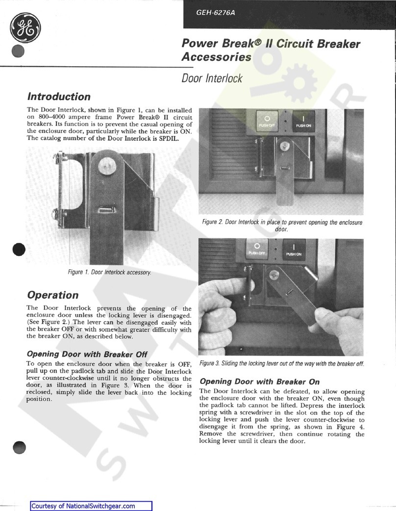
GE
GE AK-15 User manual

GE
GE EntelliGuard GBKRKR User manual

GE
GE MicroVersaTrip AKR-75 User manual

GE
GE Power Break II User manual

GE
GE PowerVac GEK-86132G User manual

GE
GE WavePro 3200 A User manual