manuals.online logo
Brands
  1. Home
  2. •
  3. Brands
  4. •
  5. Rockwell Automation
  6. •
  7. Circuit Breaker
  8. •
  9. Rockwell Automation Allen-Bradley 140U User manual

Rockwell Automation Allen-Bradley 140U User manual

Other manuals for Allen-Bradley 140U

3

Other Rockwell Automation Circuit Breaker manuals

Rockwell Automation Allen-Bradley 140MP-A-ENY65 User manual

Rockwell Automation

Rockwell Automation Allen-Bradley 140MP-A-ENY65 User manual

Rockwell Automation Allen-Bradley 140U User manual

Rockwell Automation

Rockwell Automation Allen-Bradley 140U User manual

Rockwell Automation 1492-GS1 Series User manual

Rockwell Automation

Rockwell Automation 1492-GS1 Series User manual

Rockwell Automation Allen-Bradley 140G-G User manual

Rockwell Automation

Rockwell Automation Allen-Bradley 140G-G User manual

Rockwell Automation Allen-Bradley 1397 User manual

Rockwell Automation

Rockwell Automation Allen-Bradley 1397 User manual

Rockwell Automation Allen-Bradley 140U Manual

Rockwell Automation

Rockwell Automation Allen-Bradley 140U Manual

Rockwell Automation Allen-Bradley 140M-C-TRE User manual

Rockwell Automation

Rockwell Automation Allen-Bradley 140M-C-TRE User manual

Rockwell Automation Allen-Bradley LSI User guide

Rockwell Automation

Rockwell Automation Allen-Bradley LSI User guide

Rockwell Automation Allen-Bradley 140G-N User manual

Rockwell Automation

Rockwell Automation Allen-Bradley 140G-N User manual

Rockwell Automation 189-CL1 Series User manual

Rockwell Automation

Rockwell Automation 189-CL1 Series User manual

Popular Circuit Breaker manuals by other brands

ABB SACE Emax 2 E2.2 manual

ABB

ABB SACE Emax 2 E2.2 manual

Eaton NOVA LBS 15 Installation and operation instructions

Eaton

Eaton NOVA LBS 15 Installation and operation instructions

Gewiss 90 RCD Installation

Gewiss

Gewiss 90 RCD Installation

ABB SACE Emax E1 quick start guide

ABB

ABB SACE Emax E1 quick start guide

Siemens SIRIUS 3RV1742 Original operating instructions

Siemens

Siemens SIRIUS 3RV1742 Original operating instructions

WEG FHU ACW125 installation instructions

WEG

WEG FHU ACW125 installation instructions

Siemens Sentron 3VA9157-0PK1 Series operating instructions

Siemens

Siemens Sentron 3VA9157-0PK1 Series operating instructions

hager TS 303 User instruction

hager

hager TS 303 User instruction

ETI EFI-4B Instructions for mounting

ETI

ETI EFI-4B Instructions for mounting

nader NDM3EU-225 operating instructions

nader

nader NDM3EU-225 operating instructions

TERASAKI NHP TemBreak PRO P160 Series installation instructions

TERASAKI

TERASAKI NHP TemBreak PRO P160 Series installation instructions

Gladiator GCB150 Installation instruction

Gladiator

Gladiator GCB150 Installation instruction

Eaton 50DHP-VR Instruction handbook

Eaton

Eaton 50DHP-VR Instruction handbook

ABB SACE Emax 2 E6.2 Instruction handbook

ABB

ABB SACE Emax 2 E6.2 Instruction handbook

OEZ LFN Instructions for use

OEZ

OEZ LFN Instructions for use

Eaton Power Defense PDG2 Instruction leaflet

Eaton

Eaton Power Defense PDG2 Instruction leaflet

Bticino L4412CM2 quick start guide

Bticino

Bticino L4412CM2 quick start guide

Eaton S-T0 Instruction leaflet

Eaton

Eaton S-T0 Instruction leaflet

manuals.online logo
manuals.online logoBrands
  • About & Mission
  • Contact us
  • Privacy Policy
  • Terms and Conditions

Copyright 2025 Manuals.Online. All Rights Reserved.

Installation Instructions
for
I-Frame Molded Case
Circuit
Breakers and Molded
Case
Switches
WARNING
DO
NOT
ATTEMPT
TO
INSTALL
OR
PERFORM
GIZED.
DEATH,
SEVERE
PERSONAL INJURY
OR
SUBSTANTIALPROPERTY DAMAGE CAN RESULT
FROM
CONTACT
WITH ENERGIZED
EQUIPMENT.
ALWAYS
VERIFY
THAT
NO
VOLTAGE IS
PRESENT
BEFORE
PROCEEDING
WITH
THE
TASK,
AND
ALWAYS FOLLOW GENERALLY
ACCEPTED
SAFETY
PROCEDURES.
MAINTENANCE
ON
EQUIPMENT WHILE
IT
IS
ENER
-
ALLEN-BRADLEY
IS
NOT LIABLE
FOR
THE
MISAPPLICATION OR MISINSTALLATION OF
ITS
PRODUCTS.
The user iscautionedto observe
all
recommendations,
warnings andcautionsrelating to the safety of
personnel
andequipment,
as
well
as
all
general and local health
andsafety laws,codes, andprocedures.
The recommendationsand informationcontained herein
are basedon Allen-Bradleyexperienceandjudgment,
but shouldnot beconsidered to be all-inclusive
or
coveringeveryapplication or circumstancewhich may
arise.
If
any questionsarise, contact Allen-Bradley for
further information
or
instructions.
1,
INTRODUCTION
Fig,
7-1.
I-Frame
Circuit Breaker
and
Molded Case
Switches
The 140U-I-Frame
circuit breakers (Fig. 1-1)
are ratedfrom 15Ato 225A continuous
currentand are available as thermal
-
magnetic
circuit breakers and moldedcase switches.
Circuit breakers are listedin accordancewith
Underwriters Laboratories, Inc. Standard UL489,
andsatisfythe (P1) requirements of the
International ElectrotechnicalCommission
Recommen
dation No. IEC 157-1.
Moldedcase
switches
are
listedin accordance with UL1087.
For
this publication, the term circuit breaker
also
2.
INSTALLATION
The installationprocedureconsists of inspecting and
mountingthecircuit breaker, connecting andtorquing
the
lineand loadterminations, andattaching terminalshields
or barriers,when supplied.
To
installthe circuit breaker,
perform
the
following steps:
Note:
The I-Frame circuit breakersare factory sealed. UL489
requires that internalaccessories be installedat the
factory. Where localcodes and standards permit and
UL listing is not required, internalaccessories can be
field installed. Accessory installationshould be done
before the circuit breaker is mountedand connected.
Mountinghardware and unmountedterminations (where
required) aresuppliedinseparate packages.
2
-
1.
Make
sure
that
thecircuit breaker is suitablefor the
installation
by
comparing nameplate
data
with system
requirements. Inspectthe circuit breakerfor completeness
BEFORE
MOUNTING
THE CIRCUIT BREAKER
IN
AN
ELECTRICALSYSTEM, MAKESURETHERE
IS NO
VOLTAGE PRESENTWHERE
WORK
IS
TO
BE
PER
-
FORMED. THEVOLTAGES IN ENERGIZED
EQUIP
-
MENT
CAN
CAUSE
INJURY
OR DEATH.
Bul. 140U
includes molded case switches.
.
40752-162(1) Effective 7/07
and check for damage before mounting.
2
-
2.
Dependingon theequipment configuration, the
circuit breakercan be mounted usingdifferent styles
of
hardware. The following steps describe how
to
mount
the circuit breakerusingstandard hardware. When
special hardwareisneeded (for example,with the
electricaloperator), the instruction leafletdescribingthe
accessory
also
describesthespecial mounting
arrangements.
Note:
Beforemountingthe circuit breaker, check if the
termination devicesshould be installedfirst. See termi
-
nationsinstructions.
2
-
3.
To
mountthe circuit breaker,performthefollowing
steps:
a. For individual mountingpanels, make sure that
mountingpanelis predrilled using boltdrilling plan
(Fig.
2
-
1).
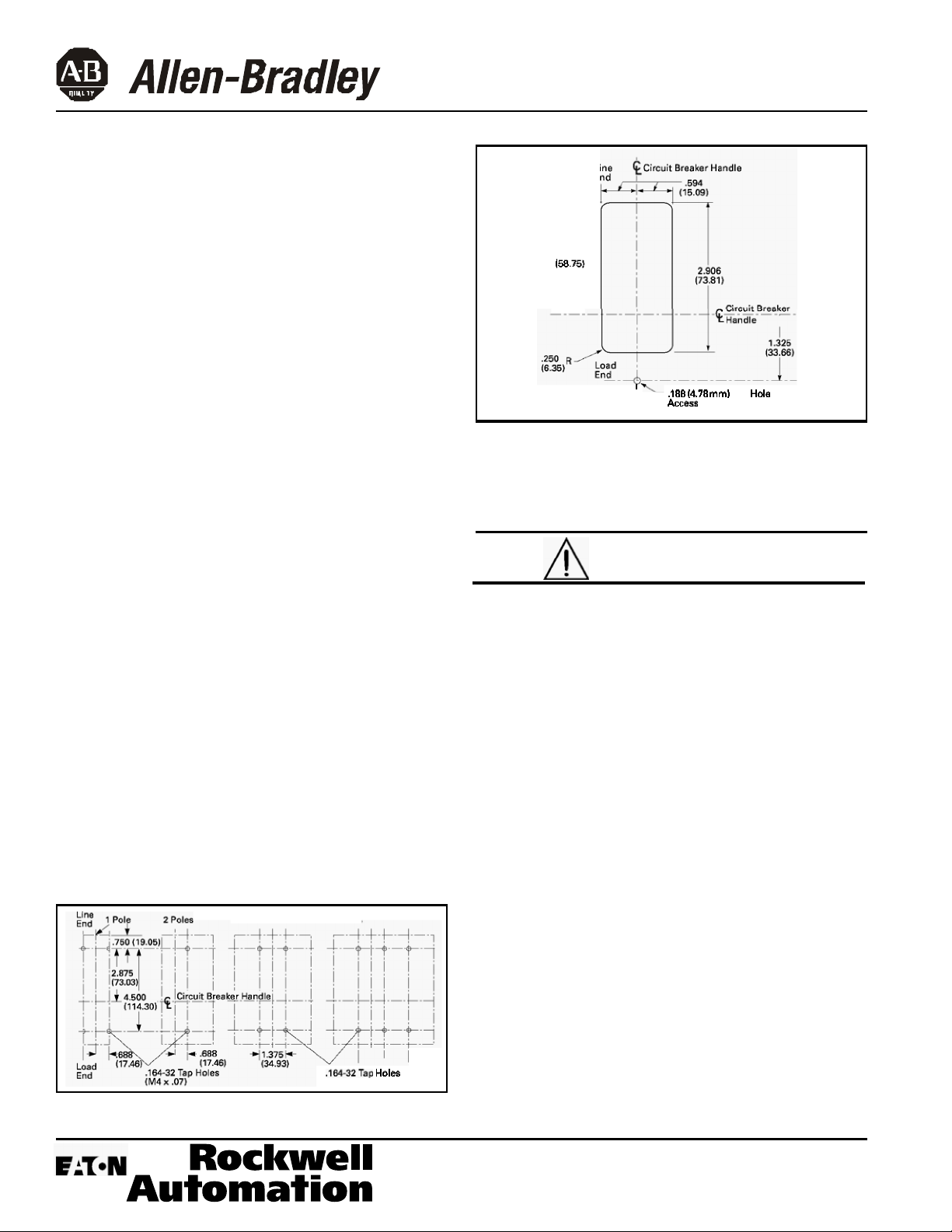
Fordeadfront cover applications
make
sure panelcover iscut out to
correct escutcheondimensions (Fig. 2-2)
).
T
2913
158.751
I
'
,188
(478
mm)
Dia.
Hde
for
Access
to
Push
-
to-Trip
Fig.
2
-
2. Circuit
Breaker
Escutcheon Dimensions
2
-
4.
If
anoptional terminal endcover isto beinstalled
with thecircuit breaker (usually line end only), it must be
positionedbeforecable is connectedtoterminals.
b.
If
circuit breakerincludesfactory installedinternal
accessories, makesure accessorywiring can be
reachedwhen the circuit breaker is mounted.
c. Positioncircuit breaker on mountingsurface.
d.
Installmountingscrews, washers, and nuts.Tighten
screws firmly, but do not exceed
28
pound
-
inches
(3.16 N.m.).
N.m.).
3
Poles
4
Poles
.164-32Tap
Holes
(M4
x
.07)
WHEN ALUMINUM CONDUCTORSARE USED,
THE
APPLICATION OF
A SUITABLE
JOINT
COMPOUND
IS
RECOMMENDED
TO
REDUCE
THE
POSSIBILITY
OF
TERMINALOVERHEATING.TERMINALOVERHEATING
CAN
CAUSE NUISANCE
TRIPPING
AND DAMAGE
TO
THE
CIRCUIT
BREAKER.
2
-
5.
After mountingthecircuit breaker, line and load
terminals andaccessory leads should be connected.
(See accessoryschematic diagram on side of circuit
breaker.
)
Note:
If
terminalshield
or
interphase barriersare
to
be
installedon the circuit breaker,installthem afterthe
terminals are connected.
2
-
6.
If
required, installterminalshieldon circuit breaker
coverwith mountingscrews provided.
2
-
7.
If
required, installan interphase barrier by sliding
barrierintodovetail grooves betweenterminals.
2
-
8.
After the circuit breakeris installed, check all
mounting hardwareand terminalconnectinghardware
for correct
torque loading.
Torque values for line/load
terminals are given inTables
2
-
1
and
2
-
2
andon the
circuit breakernameplate.
Fig,
2
-
1. Circuit Breaker Mounting Bolt Drilling Plans
40752-162(1)
Effective
7/07
CAUTION
Page
3
Note: Inthe event of athermaltrip, the circuit breaker
cannot be reset untilthe thermal element cools.
Handle
Positon
lrdiator
Galor:
Fig.
3
-
I.
Circuit Breaker
Manual Controls
3.
MANUAL
OPERATION
Manualoperationof the circuitbreaker is controlled by
thecircuitbreaker handle and the PUSH-TO-TRIP
button.The circuit broakerhandle
has
three indicated
positions,
two
of which are shown
on
the cwerwith
raisedletteringto indicate
ON
and
OFF.
On
the sliding
handle barrier,
ON,
OFF,
and trip are
also
shown
by
a
color-codedstripfor each circuit breaker handleposition:
redfor
ON,
white
for
tripped, and green for
OFF.
On the
sliding handle barrier, ON/OFF is
also
shownwiththe
internationalsymbols 1/0
(See
Fig.
3
-
1
.)
CIRCUIT
BREAKER
RESET
After
tripping,the circuit
breaker
is reset
by moving
the
circuit breakerhandle
to
the extreme
OFF
position.
PUSH
-
TO
-
TRIP BUTTON
The
PUSH
-
TO
-
TRIP
buttonchecks thetrippingfunction
andisusedto periodicallyexercisethe operating
mechanism.
4.
INSPECTIONAND FIELDTESTING
140U
moldedcase circuit breakers are designedto
provideyears of
almost
maintenance-freeoperation. The
following proceduredescribeshowto inspect and test
a
circuit breaker insewice.
INSPECTION
Circuit breakers i
n service
should
be
Inspected periodi-
cally. The inspectionshould includethefollowingchecks
4
-
1
thru4
-
7.
~~
BEFORE INSPECTING THE CIRCUIT BREAKER
IN
AN
ELECTRICALSYSTEM,
MAKE
SURE
THE
CIRCUIT
BREAKER IS SWITCHED
TO
THE
OFF
POSITIONAND
THERE
IS
NO
VOLTAGE
PRESENT
WHERE
WORK
IS
TO
BE PERFORMED. SPECIAL ATTENTION
SHOULD
BE
PAID
TO
REVERSE
FEED APPLICATIONS
TO
ENSURE
NOVOLTAGE IS PRESENT. THE VOLTAGES
IN ENERGIZED
EQUIPMENT
CAN CAUSE
INJURY
OR
DEATH.
A
CAUTION
MAKESURETHAT CLEANING AGENTS
OR
SOL
-
VENTS
USED
TO
CLEAN
THE
CIRCUIT
BREAKER
ARE
SUITABLE
FOR
THE
JOB.
SOME COMMERCIAL
PLATESOR
MOLDED
PARTS.
CLEANING AGENTS
WILL
DAMAGE
THE
NAME
-
4
-
1.
Removedust, dirt, soot, grease,
or
moisturefrom
the surface
of
the circuit breakerusing
a
lint-freedry
cloth, brush,
or
vacuum cleaner.
Do
not
blowdebris into
circuit
breaker.
If contamination is
found,
lookfor the
source
and
eliminatethe problem.
4
-
2.
Switchcircuit breakerto
ON
and
OFF
severaltimes
to be
sure
that the mechanicallinkagesarefree and do
not bind.
If
mechanicallinkagesare not free, replace
circuit breaker.
40752-162(1) Effective 7/07
Page 4
4-3.
Pressthe PUSH-TO-TRIPbutton
to
mechanically
tripthe circuit breaker.Trip, reset, and switch circuit
breaker
ON
severaltimes.
If
mechanism
does
not reset
each time the circuit breaker istripped, replacethe circuit
breaker.
44.
Check base,cover, andoperatinghandle
for
cracks,
chipping, and discoloration.Circuit breakers should be
replaced
if
cracksor severediscoloration is found.
4-5.
Checkterminals and connectorsfor loosenessor
signs
of
overheating. Overheatingwill
show
as
discolora
-
tion, melting, or blistering
of
conductorinsulation,
or
as
pitting
or
melting
of
conductorsurfacesdue
to
arcing.
If
there is no evidence
of
overheating
or
looseness, do not
disturb
or
tightenthe connections. If there is evidence of
overheating,terminationsshould
be
cleaned
or
replaced.
Before re
-
energizingthe circuit breaker,
all
terminations
and
cable should be refurbished
to
the conditionwhen
originallyinstalled.
4-6.
Checkcircuit breaker mounting hardware. Tighten if
necessary.
4-7.
Checkareawhere circuit breaker is installedfor any
safety hazards, including personal safetyandfire
hazards. Exposure
to
certain
types
of
chemicalscan
cause deterioration
of
electricalconnections.
FIELD
TESTING
Any field testingshouldbe done inaccordancewith
NEMA
Standards Publication
AB2
-
1984.
40752-162(1) Effective 7/07
Printed in USA