Telect Broadband Connectivity System II User manual

Artisan Technology Group is your source for quality
new and certied-used/pre-owned equipment
• FAST SHIPPING AND
DELIVERY
• TENS OF THOUSANDS OF
IN-STOCK ITEMS
• EQUIPMENT DEMOS
• HUNDREDS OF
MANUFACTURERS
SUPPORTED
• LEASING/MONTHLY
RENTALS
• ITAR CERTIFIED
SECURE ASSET SOLUTIONS
SERVICE CENTER REPAIRS
Experienced engineers and technicians on staff
at our full-service, in-house repair center
WE BUY USED EQUIPMENT
Sell your excess, underutilized, and idle used equipment
We also offer credit for buy-backs and trade-ins
www.artisantg.com/WeBuyEquipment
REMOTE INSPECTION
Remotely inspect equipment before purchasing with
our interactive website at www.instraview.com
LOOKING FOR MORE INFORMATION?
Visit us on the web at www.artisantg.com for more
information on price quotations, drivers, technical
specications, manuals, and documentation
Contact us: (888) 88-SOURCE | sales@artisantg.com | www.artisantg.com
SM
View
Instra
© Telect, Inc., All Rights Reserved, 117389-5 A0
1.509.926.6000 :: telect.com
Broadband Connectivity System II
Copper :: Part Number 117389-4
User Manual
Applys to: :: 010-3232-0001 :: 010-3224-0001 :: 010-3201-0407 :: 010-3201-0401 :: 010-3201-0410 :: 710-3201-0002
:: 710-3201-0005 :: 710-3201-1001-U :: 710-3201-1002-U :: 710-3201-2001-U :: 710-3201-2002-U
:: 010-0000-3201BCS :: 010-0000-1401BCS :: 010-0000-2401BCS :: 010-0000-1471BCS :: 010-0000-0471BCS
Artisan Technology Group - Quality Instrumentation ... Guaranteed | (888) 88-SOURCE | www.artisantg.com

© Telect, Inc., All Rights Reserved, 117389-5 A0
1.509.926.6000 :: telect.com
ii
Broadband Connectivity System II
Copper :: Part Number 117389-4
Table of Contents
Chapter 1: Description ..........................................................................................................1
1.1 Overview.........................................................................................................................1
1.1.1 Capabilities..............................................................................................................3
1.1.2 Features..................................................................................................................3
1.2 DSX Chassis & Passive Card Modules ..........................................................................4
1.2.1 DSX-3 Rear Cross-Connect Chassis...................................................................... 4
1.2.2 Fully Loaded DSX-3 Chassis .................................................................................. 9
1.2.3 DSX Passive Card Modules..................................................................................10
1.3 DNI Chassis & Passive Card Modules ......................................................................... 11
1.3.1 DNI Chassis (Telect Model 010-0000-1402BCS).................................................. 11
1.3.2 Fully Loaded 19-in. DNI Chassis (Telect Model 010-3224-0402) .........................12
1.3.2.1 DNI-3 Card Module (Telect Model 010-3201-0402) ........................................... 12
1.4 BSCII Active Card Modules ..........................................................................................12
1.4.1 Repeater Card Modules........................................................................................13
1.4.2 Vector Optical Transport Module (OTM) Card Modules........................................ 13
1.5 Power Distribution.........................................................................................................14
1.6 Specications................................................................................................................15
1.6.1 DSX Electrical1.6.2 Mechanical............................................................................15
1.6.3 Environmental .......................................................................................................15
Chapter 2: Installation.........................................................................................................16
2.1 Installation Considerations............................................................................................16
2.1.1 Location and Space ..............................................................................................16
2.1.2 Computer Floor Issues..........................................................................................17
2.1.3 Required Tools and Equipment.............................................................................17
2.2 Inspection .....................................................................................................................17
2.3 Installation.....................................................................................................................17
Chapter 3: Electrical Operation...........................................................................................24
3.1 Power............................................................................................................................24
3.1.1 Tracer Lamps (TL).................................................................................................25
3.1.2 Monitor Ports.........................................................................................................25
3.2 DSX Cross-Connections...............................................................................................25
3.2.1 Backplane Cross-Connections..............................................................................25
3.2.2 DSX Card Front Patch ..........................................................................................27
3.3 Repeater Cards ............................................................................................................27
3.3.1 Simplex Repeater Card.........................................................................................27
3.3.2 Duplex Repeater Card ..........................................................................................29
3.4 DNI Operations .............................................................................................................30
3.4.1 Basic Function: Digital Network Interconnection................................................... 30
3.4.2 Interconnect Network Elements Using DNI Cards ................................................ 31
3.4.3 DNI Card Monitoring .............................................................................................31
3.4.4 DNI Patching.........................................................................................................32
3.5 Skeleton Bay Options ...................................................................................................33
Chapter 4: Service ..............................................................................................................35
4.1 Owner Maintenance......................................................................................................35
Artisan Technology Group - Quality Instrumentation ... Guaranteed | (888) 88-SOURCE | www.artisantg.com

© Telect, Inc., All Rights Reserved, 117389-5 A0
1.509.926.6000 :: telect.com iii
Broadband Connectivity System II
Copper :: Part Number 117389-4
4.2 Troubleshooting Cross-Connected Signals ..................................................................35
4.3 Replacing the Tracer Lamp LED...................................................................................35
4.4 Service..........................................................................................................................35
4.4.1 In-Warranty Service ..............................................................................................35
4.4.2 Out-Of-Warranty Service.......................................................................................36
4.5 Repacking For Shipment ..............................................................................................36
Artisan Technology Group - Quality Instrumentation ... Guaranteed | (888) 88-SOURCE | www.artisantg.com

© Telect, Inc., All Rights Reserved, 117389-5 A0
1.509.926.6000 :: telect.com
iv
Broadband Connectivity System II
Copper :: Part Number 117389-4
List of Figures
Figure 1 - 23-inch, 32-circuit BCSII With 6-Port DSX Card Modules.................................... 1
Figure 2 - DSX Modules .......................................................................................................2
Figure 3 - Other Modules......................................................................................................2
Figure 4 - 23-inch DSX Chassis (Telect Model 010-0000-3201BCS) ................................... 5
Figure 5 - 23-inch DSX Chassis - Rear View Showing BNC Connectors............................. 5
Figure 6 - 19-inch DSX Chassis (Telect Model 010-0000-2401BCS) ................................... 6
Figure 7 - 19-inch DSX Chassis - Rear View Showing BNC Connectors............................. 6
Figure 8 - 23-inch Chassis with 24 Card Module Slots.........................................................7
Figure 9 - 23-inch Chassis with 24 Card Module Slots ........................................................8
Figure 10 - 10-Module, 23-inch Horizontal Chassis ............................................................. 8
Figure 11 - 8-Module, 19-inch Horizontal Chassis (Telect Model 010-0000-0471BCS) .......9
Figure 12 - 8-Module, 19-inch Horizontal Chassis ............................................................... 9
Figure 13 - DSX Cross-Connect Modules (Mini-Weco Front Jacks) ..................................10
Figure 14 - 23-inch DNI-3 Chassis (Telect Model 010-0000-1402BCS) ............................. 11
Figure 15 - 23-inch DNI-3 Chassis - Rear View Showing BNC Connectors....................... 11
Figure 16 - DNI-3 Card Module ..........................................................................................12
Figure 17 - Simplex Repeater (710-3201-0002) .................................................................13
Figure 18 - Vector OTM with SC Connectors .....................................................................14
Figure 19 - Dual-Feed 25A GMT Power Distribution Panel With Fuse Alarms...................14
Figure 20 - Rack .................................................................................................................16
Figure 21 - Mounting Chassis to Rack................................................................................18
Figure 22 - Installing a Module ...........................................................................................19
Figure 23 - Grounding the Chassis.....................................................................................20
Figure 24 - BNC Insertion Tool ...........................................................................................20
Figure 25 - Connections .....................................................................................................21
Figure 26 - Rear Cross-Connect Cables with Tracer Wire .................................................22
Figure 27 - Power from Distribution Panel to Front Tracer Lamp ....................................... 24
Figure 28 - Tracer Lamp Operation ....................................................................................25
Figure 29 - Schematic Drawing of Cross-Connection......................................................... 26
Figure 30 - Rear Cross-Connect Cables with Tracer Wire .................................................26
Figure 31 - Temporary Front Cross-Connect Using Patch Cables & DSX Cards ............... 27
Figure 32 - Simplex Repeater.............................................................................................27
Figure 33 - Repeater Application Using Two Simplex Repeaters ....................................... 28
Figure 34 - Simplied Schematic of a Simplex Repeater Application .................................28
Figure 35 - Duplex Repeater ..............................................................................................29
Figure 36 - Repeater Application Using Two Simplex Repeaters ....................................... 29
Figure 37 - Simplied Schematic of a Duplex Repeater Application...................................30
Figure 38 - DNI ...................................................................................................................30
Figure 39 - Network Elements ............................................................................................31
Figure 40 - DNI Card Monitoring.........................................................................................31
Figure 41 - Patching Between DNI Card Modules..............................................................32
Figure 42 - Reference Schematic for DNI-3 Card Module (Model 010-3201-0402) ...........33
Artisan Technology Group - Quality Instrumentation ... Guaranteed | (888) 88-SOURCE | www.artisantg.com
© Telect, Inc., All Rights Reserved, 117389-5 A0
1.509.926.6000 :: telect.com 1
Broadband Connectivity System II
Copper :: Part Number 117389-4
1.1 Overview
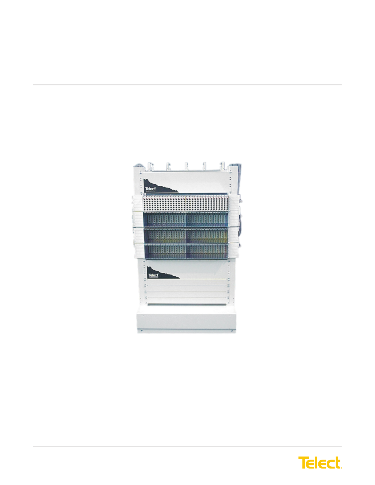
Figure 1 - 23-inch, 32-circuit BCSII With 6-Port DSX Card Modules
The Telect Broadband Connectivity System II (BCSII) is a family of related products providing a high-density
environment for cross-connecting and interconnecting DS3, STS-1, E-3, STM-1, and STS-3 signals from
broadband equipment such as digital radio, multiplexers and 3:3 or 3:1 DCS. Available components include
several 19-in and 23-in chassis with integrated backplanes.
The chassis accommodate three, four, or six-port DSX and six-port DNI card modules with frontpanel patching.
Other Telect card modules (simplex and duplex repeaters and optical/electrical
Chapter 1: Description
Artisan Technology Group - Quality Instrumentation ... Guaranteed | (888) 88-SOURCE | www.artisantg.com

© Telect, Inc., All Rights Reserved, 117389-5 A0
1.509.926.6000 :: telect.com
2
Broadband Connectivity System II
Copper :: Part Number 117389-4
[optical transport module] converters) can be inserted into the chassis and used along with DSX and DNI card
modules for added exibility and adaptability.
Three-Port DSX Module Four-Port DSX Module Six-Port DSX Module
Figure 2 - DSX Modules
Simplex Repeater Module Duplex Repeater Module Vector OTM Module
Card module may appear
somewhat different than
pictured here.
Figure 3 - Other Modules
Artisan Technology Group - Quality Instrumentation ... Guaranteed | (888) 88-SOURCE | www.artisantg.com
© Telect, Inc., All Rights Reserved, 117389-5 A0
1.509.926.6000 :: telect.com 3
Broadband Connectivity System II
Copper :: Part Number 117389-4
1.1.1 Capabilities
The Telect DSX-3 system enables patching, cross-connecting, interconnecting, test and monitor
functions for digital signals in 75 ohm systems for the following bit rates:
E3 34.368 Mbps
DS3 44.736 Mbps
STS-1 51.84 Mbps
STS-3 155.52 Mbps
STM-1 155.52 Mbps
The maximum number of cross-connect cards in a 7 ft x 23 in. x 12 in. equipment bay with 14
chassis is 448 cards.
1.1.2 Features
The BCS II has the following features:
• There are 32-active or mixed circuits per chassis; 48 per passive 8 x 23 in. chassis.
• Customers can pre-terminate network elements and pre-wire cross-connect assignments on-site.
• Front and rear tracer lamps display circuit cross-connects.
• Bidirectional monitoring is available.
• Card modules use Mini-WECO jacks and BNC or 1.6/5.6 connectors.
• The BCS II provides exible cable management options.
• DNI cards and DNI-only chassis are available. (Note that the DNI card modules do not require power.)
• DNI cards t DSX chassis.
• The BCS II provides 19 in. or 23 in. chassis.
• The BCS II is available for WECO, EIA, ETSI racks.
• Modules can be mixed in the same chassis.
• Alarm outputs are available on the DSX chassis for those active card modules capable of generating critical,
major, and/or minor alarms
Artisan Technology Group - Quality Instrumentation ... Guaranteed | (888) 88-SOURCE | www.artisantg.com
© Telect, Inc., All Rights Reserved, 117389-5 A0
1.509.926.6000 :: telect.com
4
Broadband Connectivity System II
Copper :: Part Number 117389-4
1.2 DSX Chassis & Passive Card Modules
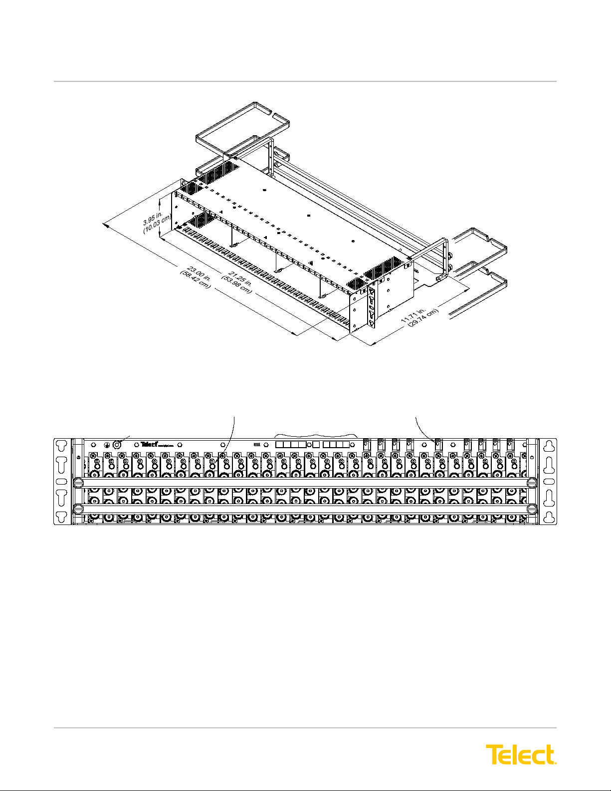
1.2.1 DSX-3 Rear Cross-Connect Chassis
Typical DSX-3 rear cross-connect chassis are shown in the illustrations on the following pages:
• 23-in., 32-Circuit DSX Chassis, page 5
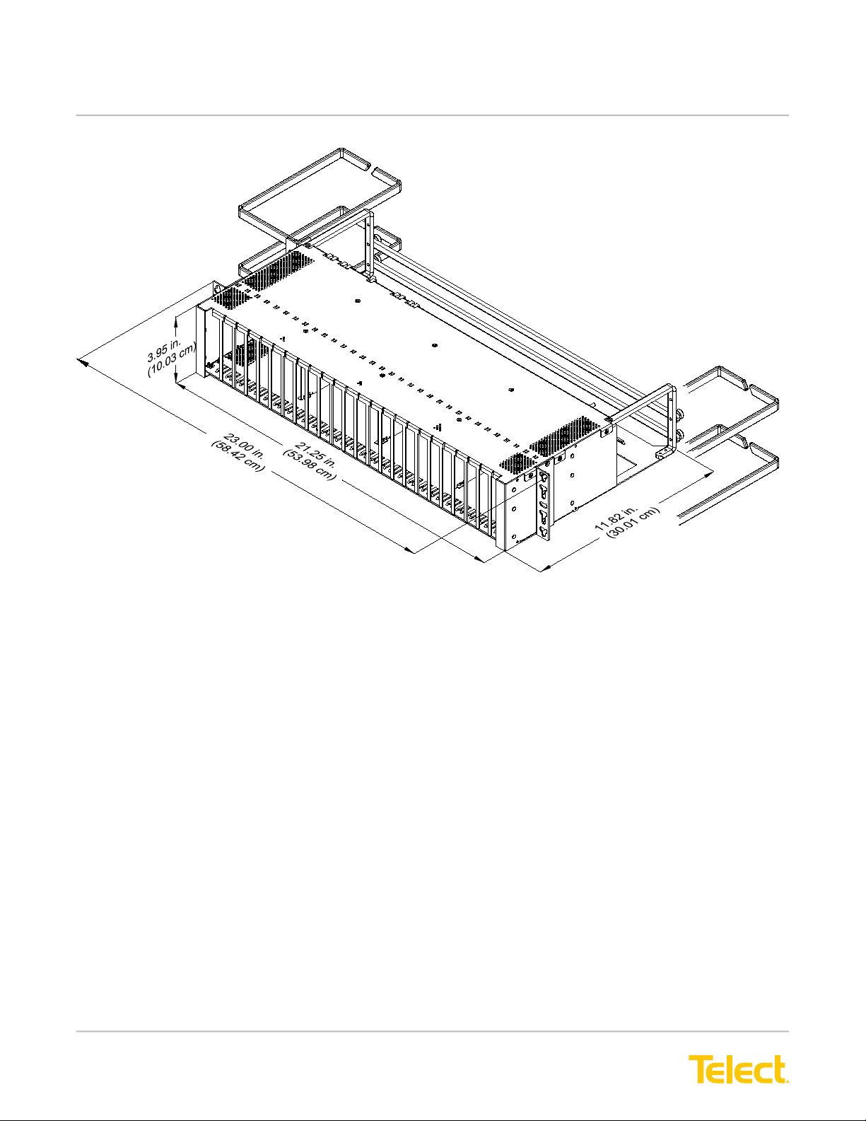
• 19-in., 24 -Circuit DSX Chassis, page 6
• 23-in., 24-Circuit DSX Chassis, page 7
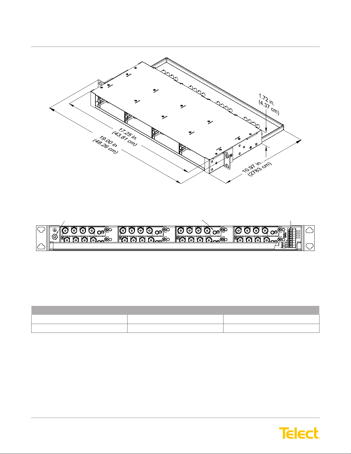
• 23- & 19-in. Horizontal Chassis (10 & 8 Circuits, respectively), page 8 & 9
All DSX chassis have integrated backplanes with tracer lamps. Vertical DSX chassis can accommodate any active
or passive BCSII card module.
Rear plates with BNC connections are alternately nished black, white, black, white, etc.
The following table lists all empty 19-in. and 23-in DSX-3 chassis models. Fully pre-loaded
chassis containing DSX modules are listed in the following subsection.
HxDxW Dimensions (in/cm) Number of card slots Telect Part Number
3.95/10.03 x 11.81/29.98 x
23.01/58.43
32 010-0000-3201BCS
3.95/10.03 x 11.82/30.01 x
23.00/58.43
24 010-0000-1401BCS
3.95/10.03 x 11.87/30.14 x
19.00/48.26
24 010-0000-2401BCS
1.72/4.37 x 7.59/19.38 x
23.00/58.43
10, horizontal 010-0000-1471BCS
1.72/4.37 x 7.59/19.38 x
19.00/48.26
8, horizontal 010-0000-0471BCS
Artisan Technology Group - Quality Instrumentation ... Guaranteed | (888) 88-SOURCE | www.artisantg.com
© Telect, Inc., All Rights Reserved, 117389-5 A0
1.509.926.6000 :: telect.com 5
Broadband Connectivity System II
Copper :: Part Number 117389-4
A
BATT
A
RTN
B
RTN
GND
C.
COM
ALM
MAJ
ALM
MIN
ALM
PWR
ALM
B
BATT
Legend
8 - 32 Stud & Nut for Ground Lug
Tracer Lamp Spring Clamp Connector
263031 29 28 27 25 24 2223 21 1820 19 17 16 15 14 13 8 6 1
A
BATT
A
RTN
B
RTN
GND
C.
COM
ALM
MAJ
ALM
MIN
ALM
PWR
ALM
B
BATT
5A MAX -48V
Figure 4 - 23-inch DSX Chassis (Telect Model 010-0000-3201BCS)
Figure 5 - 23-inch DSX Chassis - Rear View Showing BNC Connectors
Artisan Technology Group - Quality Instrumentation ... Guaranteed | (888) 88-SOURCE | www.artisantg.com

© Telect, Inc., All Rights Reserved, 117389-5 A0
1.509.926.6000 :: telect.com
6
Broadband Connectivity System II
Copper :: Part Number 117389-4
GND
ALM
ALMALM
MAJCOM MIN
Legend RTN
BAA
BATT RTN
B
BATT C.
MAJCOM
ALM ALM
PWRMIN
ALMALM
18
GND
ALM
PWR
RTNRTNBATT
AA B
BATT C.
B
5A MAX
-48V
Spring Clamp Connectors
17 16 15 1314 122324 22 21 20 19 57
Tracer Lamp
8 - 32 Stud & Nut for Ground Lug
Figure 6 - 19-inch DSX Chassis (Telect Model 010-0000-2401BCS)
Figure 7 - 19-inch DSX Chassis - Rear View Showing BNC Connectors
Artisan Technology Group - Quality Instrumentation ... Guaranteed | (888) 88-SOURCE | www.artisantg.com
© Telect, Inc., All Rights Reserved, 117389-5 A0
1.509.926.6000 :: telect.com 7
Broadband Connectivity System II
Copper :: Part Number 117389-4
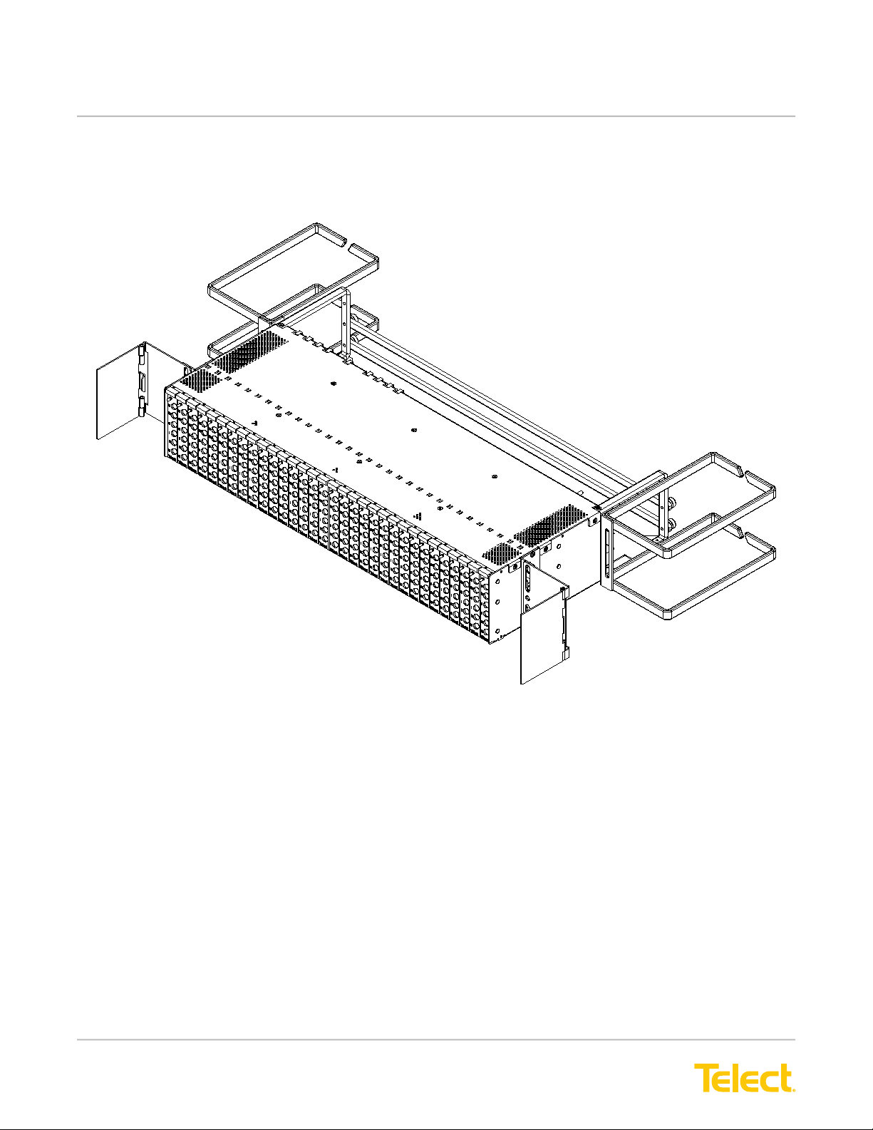
Figure 8 - 23-inch Chassis with 24 Card Module Slots
(Telect Model 010-0000-1401BCS)
Artisan Technology Group - Quality Instrumentation ... Guaranteed | (888) 88-SOURCE | www.artisantg.com

© Telect, Inc., All Rights Reserved, 117389-5 A0
1.509.926.6000 :: telect.com
8
Broadband Connectivity System II
Copper :: Part Number 117389-4
Spring Clamp Connectors
MAJ
MINALARMS
COM
PWR
8 - 32 Stud & Nut for Ground Lug Tracer Lamp
- A
- B
+ B
+ A
Figure 9 - 23-inch Chassis with 24 Card Module Slots (Telect Model 010-0000-1401BCS)
Figure 10 - 10-Module, 23-inch Horizontal Chassis — Rear View Showing BNC Connectors
Artisan Technology Group - Quality Instrumentation ... Guaranteed | (888) 88-SOURCE | www.artisantg.com
© Telect, Inc., All Rights Reserved, 117389-5 A0
1.509.926.6000 :: telect.com 9
Broadband Connectivity System II
Copper :: Part Number 117389-4
- A
+ A
- B
+ B
COM
PWR
MAJ
MINALARMS
Spring Clamp Connectors
8 - 32 Stud & Nut for Ground Lug Tracer Lamp
Figure 11 - 8-Module, 19-inch Horizontal Chassis (Telect Model 010-0000-0471BCS)
Figure 12 - 8-Module, 19-inch Horizontal Chassis — Rear View Showing BNC Connectors
1.2.2 Fully Loaded DSX-3 Chassis
The following table lists the fully loaded DSX-3 models.
Chassis Width (in/cm) #cards Telect Part Number
23/58.43 32 010-3232-0001
23/58.43 24 010-3224-0001
Fully loaded chassis include the following:
• BNC Rear I/O and XI/XO connectors
• 6-Port Mini-Weco front jacks
• Front and Rear Tracer Lamps
Chassis are shipped with all cards installed.
Artisan Technology Group - Quality Instrumentation ... Guaranteed | (888) 88-SOURCE | www.artisantg.com
© Telect, Inc., All Rights Reserved, 117389-5 A0
1.509.926.6000 :: telect.com
10
Broadband Connectivity System II
Copper :: Part Number 117389-4
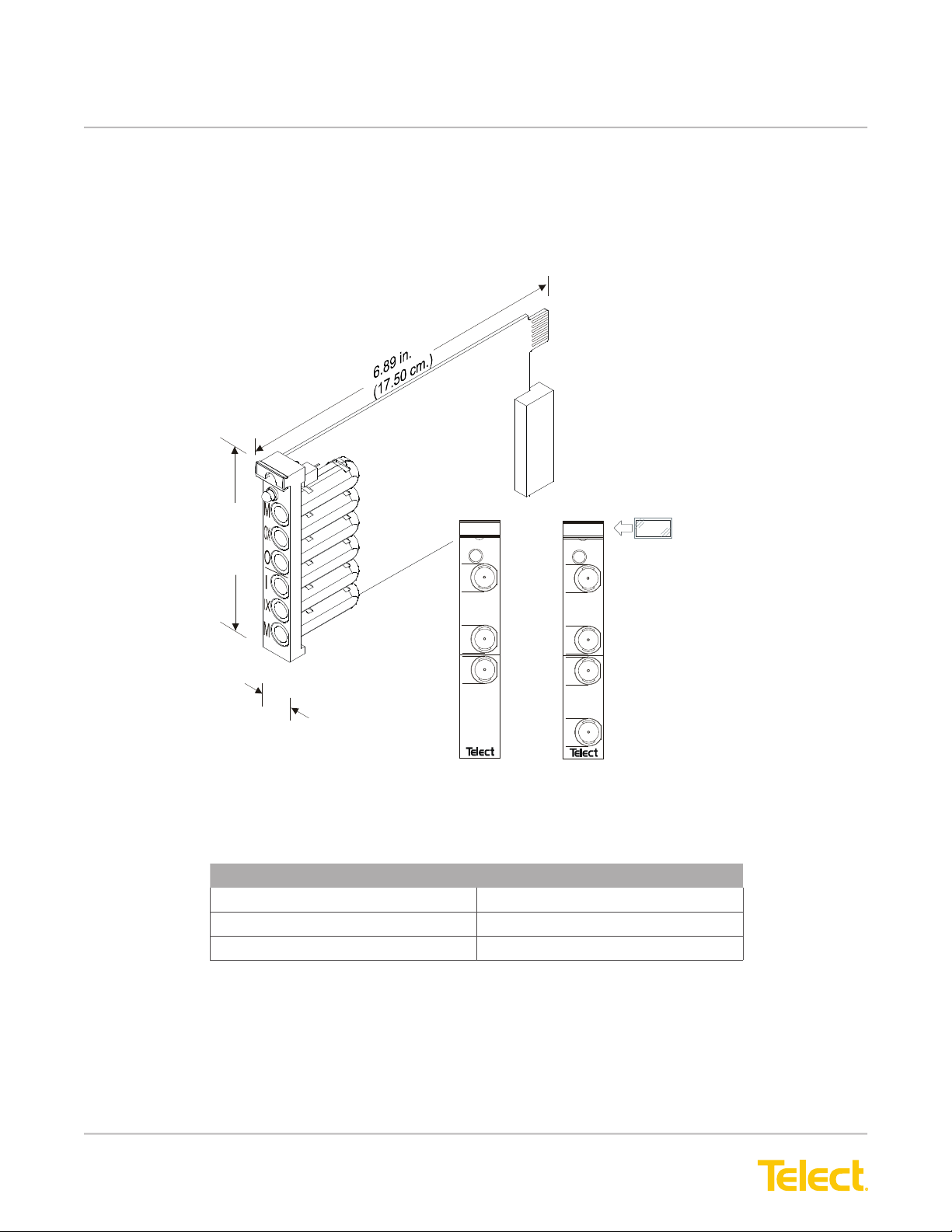
1.2.3 DSX Passive Card Modules
DSX card modules have Mini-Weco jacks at the front of the module for passive monitoring and/or cross-connection.
Rear connectors on card modules, shown in the following illustration, snap into connectors on a 23-in. or 19-in.
DSX-3 chassis backplane. All card modules have white faceplates.
6-port Card
3.93 in.
(9.98 cm.)
0.65 in.
(1.65 cm.)
M
O
I
®
M
M
O
I
®
Alternate Cards
3-port Card 4-port Card
Designation Label
and Holder
(010-3201-0410)
(010-3201-0407)
(010-3201-0401)
Figure 13 - DSX Cross-Connect Modules (Mini-Weco Front Jacks)
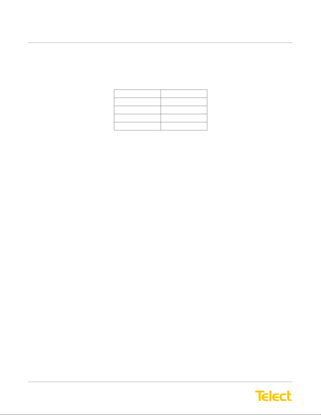
Number of Ports Telect Part Number
3 010-3201-0407
4 010-3201-0401
6 010-3201-0410
Artisan Technology Group - Quality Instrumentation ... Guaranteed | (888) 88-SOURCE | www.artisantg.com

© Telect, Inc., All Rights Reserved, 117389-5 A0
1.509.926.6000 :: telect.com 11
Broadband Connectivity System II
Copper :: Part Number 117389-4
1.3 DNI Chassis & Passive Card Modules
1.3.1 DNI Chassis (Telect Model 010-0000-1402BCS)
The following illustration shows Telect’s 23-in. DNI chassis.
Telect’s DNI-3 chassis does not have a power backplane. The chassis has rear external BNC I/O connectors for
use with DNI card modules. Although only passive DNI card modules are used in DNI chassis, the DNI card
modules can also be used in the DSX chassis.
263031 29 28 27 25 24 2223 21 1820 19 17 16 15 14 13 8 6 1
8 - 32 Stud & Nut for Ground Lug
Tracer Lamp
Figure 14 - 23-inch DNI-3 Chassis (Telect Model 010-0000-1402BCS)
Figure 15 - 23-inch DNI-3 Chassis - Rear View Showing BNC Connectors
Artisan Technology Group - Quality Instrumentation ... Guaranteed | (888) 88-SOURCE | www.artisantg.com
© Telect, Inc., All Rights Reserved, 117389-5 A0
1.509.926.6000 :: telect.com
12
Broadband Connectivity System II
Copper :: Part Number 117389-4
1.3.2 Fully Loaded 19-in. DNI Chassis (Telect Model 010-3224-0402)
The fully loaded 19-in. DNI chassis includes the following:
• DNI rear labeling (NE-1 I/O, NE-2 I/O)
• 24 DNI cards installed in a 19-in. Telect DNI-3 chassis
• BNC Rear I/O connectors
• Mini-Weco front jacks
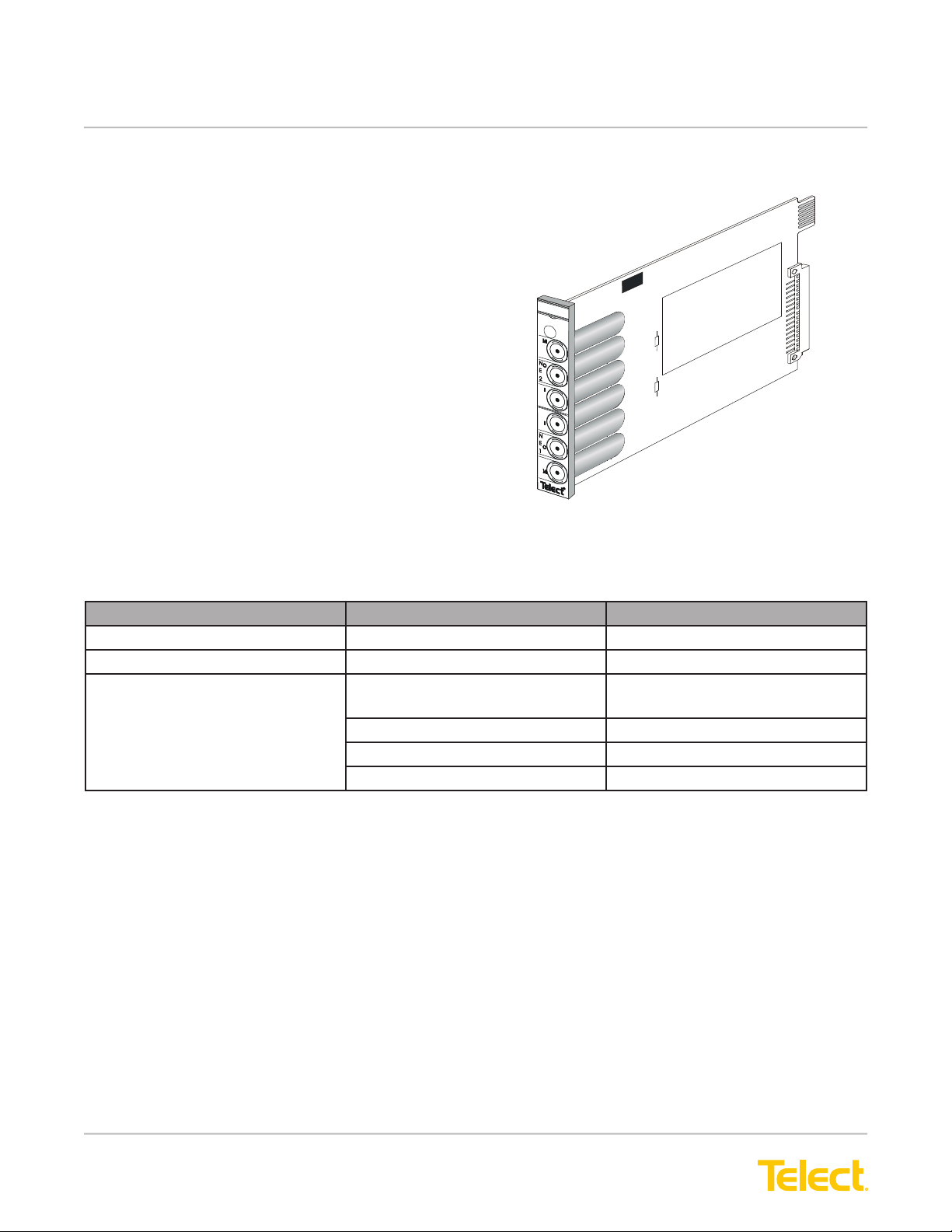
1.3.2.1 DNI-3 Card Module (Telect Model 010-3201-0402)
DNI-3 card modules, shown in the illustration on the right,
have six Mini-Weco jacks at the front of the module for
passive monitoring and patching. Rear card connectors
snap into connectors on 23-in. or 19-in. DNI or DSX chassis.
Figure 16 - DNI-3 Card Module
1.4 BSCII Active Card Modules
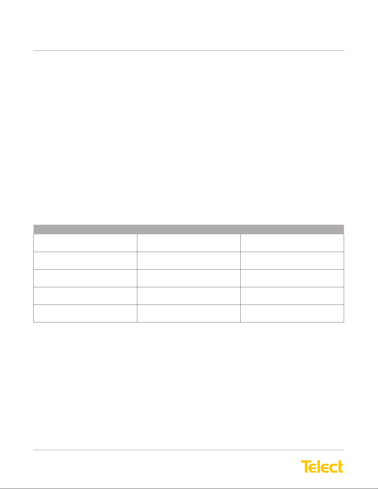
The following table gives pertinent information about
the active card modules.
Active Module Description # Cards per Chassis Telect Part Number
Simplex Repeater Module 5 710-3201-0002
Duplex Repeater Module 5 710-3201-0005
Optical/Electrical Converter,
Multimode, ST
Multimode, SC
Single mode, ST
Single mode, SC
5
710-3201-1001-U
5 710-3201-1002-U
5 710-3201-2001-U
5 710-3201-2002-U
Artisan Technology Group - Quality Instrumentation ... Guaranteed | (888) 88-SOURCE | www.artisantg.com

© Telect, Inc., All Rights Reserved, 117389-5 A0
1.509.926.6000 :: telect.com 13
Broadband Connectivity System II
Copper :: Part Number 117389-4
1.4.1 Repeater Card Modules
The repeater cards enable increased separation up to 900 feet (274 m) between crossconnected network elements,
using ATT 734A cable. Repeater cards can be stationed at 900 feet intervals to allow unlimited signal repetitions.
The simplex repeater card (710-3201-0002) is always used in pairs. The duplex repeater card (710-3201-0005)
contains two simplex repeaters with a common power supply Consult the Simplex Repeater User Manual and the
Duplex Repeater User Manual for operational details.
Figure 17 - Simplex Repeater (710-3201-0002) Duplex Repeater (710-3201-0005)
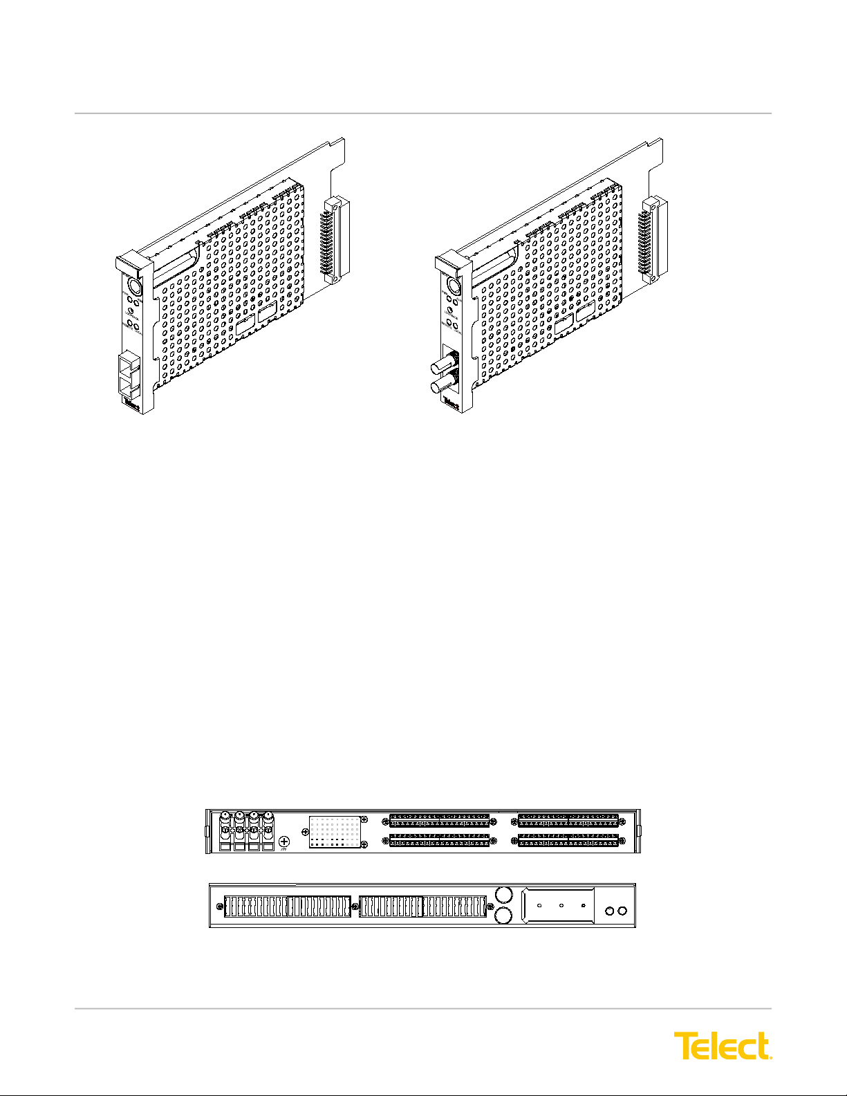
1.4.2 Vector Optical Transport Module (OTM) Card Modules
The Vector OTM (or optical/electrical converter) card modules convert single-mode or multimode ber optic
signals to electrical signals and vice versa. All ber optic connectors are located at the front of the modules.
Telect manufactures both single-mode and multimode converters with either ST or SC connectors. A
hardened version of the single mode optical/electrical converter with SC connectors is suitable for extended
temperature operation.
Consult the Vector Optical Transport Module (OTM) User Manual for operational details.
Artisan Technology Group - Quality Instrumentation ... Guaranteed | (888) 88-SOURCE | www.artisantg.com
© Telect, Inc., All Rights Reserved, 117389-5 A0
1.509.926.6000 :: telect.com
14
Broadband Connectivity System II
Copper :: Part Number 117389-4
Vector card modules may appear
somewhat different than pictured here.
Figure 18 - Vector OTM with SC Connectors Vector OTM with ST Connectors
1.5 Power Distribution
You can use a wide variety of -48Vdc power distribution panels to provide power to a DSX chassis. If your installation
includes repeaters or other active products, use a dual-feed power distribution panel (PDP) to ensure power
availability in case one power feed fails. One appropriate PDP for this application is Telect Model 06004-11, shown
in the following illustration. Model 06004-11 is a dual-feed GMT PDP with 20 fuse positions per side and a total
output load capability of 20A.
Use the following power specications to select the proper PDP for your application:
• DSX cards draw 18 mA total, 9 mA for each tracer lamp.
• Repeater cards draw up to 60 mA each.
• Optical/electrical converter cards draw up to 180 mA.each.
Fuses for each chassis must be 1-1/3 amp. Use 22 AWG wire (minimum) for power distribution to each chassis.
Use red wire to connect to RTN and black for BATT. Remember that all PDPs and BCSII chassis require grounding,
including DNI chassis.
POWER A
1510 15 20
POWER B
1510 15 20
A
B
AB
ALARM
FAIL
RELAY
NO CNC
AB
NO CNC
AB
-24V
TO
-48V
RTN
Rear View
Front View
Figure 19 - Dual-Feed 20A GMT Power Distribution Panel With Fuse Alarms
Artisan Technology Group - Quality Instrumentation ... Guaranteed | (888) 88-SOURCE | www.artisantg.com

© Telect, Inc., All Rights Reserved, 117389-5 A0
1.509.926.6000 :: telect.com 15
Broadband Connectivity System II
Copper :: Part Number 117389-4
1.6 Specications
1.6.1 DSX Electrical
Insertion Loss: 0.6 + 0.55 dB at DS3/E3 signal rates for assemblies that do not include a monitor network. < 1.00
dB at DS3/E3 signal rates for assemblies that include a single monitor point.
Monitor Level: 21 dB + 1.5 dB below signal level
Return Loss: < -26 dB at DS3/E3, STS-1 signal rates
< -26 dB at E3 signal rate of 17.184 Mhz
< -15 dB at STS-3/STM-1 signal rates
Contact Resistance: < 0.01Ω
Characteristic Impedance: 75Ω
Tracer Lamp LED: Draws 9mA at -48Vdc
1.6.2 Mechanical
Jack Insertion force: 10 lbs maximum, 4.1 lbs. minimum
Jack Withdrawal force: 7 lbs. maximum, 3.8 lbs. minimum
Jack Life: Minimum 10,000 insertion/withdrawal cycles
1.6.3 Environmental
Thermal Limits (Passive): -55°C to +85°C, operating and non-operating
Thermal Limits (Active): -55°C to +85°C, non-operating; 0°C to +50°C, operating
Thermal Shock: per MIL-STD-202, method 107D
Humidity: 0% to 95%, operating and non-operating
Artisan Technology Group - Quality Instrumentation ... Guaranteed | (888) 88-SOURCE | www.artisantg.com
This manual suits for next models
16
Table of contents
Other Telect Network Hardware manuals


