Teledif micro TSA 4.0 User manual

1
micro
TSA 4.0
Emergency Phone System
For Analog Line (POTS)
Or GSM gateway
Instruction Manual
English Ed. 1 del 04/07/2017
SW 1.1

2
THANKS TO CHOOSE
A TELEDIF ITALIA PRODUCT
To obtain the maximum performance and to use the features and functions of the micro TSA 4.0 in the best
way, read this manual carefully and keep it handy for any consultation.
Micro TSA 4.0 system is specifically designed to help, someone eventually locked in a cabin lift, to raise
an alarm to a service center.
Micro TSA 4.0 responds to the rules: Directive 95/16/EC, EN 81-28, EN 81-70, EN81-72, CTR 21;
EN 50082, EN 627 EN 50081-1:1991, EN55022, IEC EN139-4/A2: 2003, EN61000-4-2, EN61000-4-
3, EN61000-4-4, EN61000-4-6,EN61000-4-8.
Bi-directional (talk / listen)
Self-diagnosis. The main features are verified locally and remotely
Audio level programmable locally or remotely
Communication protocol to works with any call center via DTMF or Ademco Contact ID
2 Independent dial systems and communication: Cabin and Technician call
2-way communication from local phone and cabin
1 input for 3 working mode:
Main alarm filter
Gong signal
Technical alarm, with management of start and end of alarm
Warning message on/off
Calming message recordable by user
Location message
Messages identifying the type of alarm or warning and its origin
System information messages
Test call automatic and on request, programmable on days of calls
Low battery alarm, by programming the threshold level and duration of the test
Programmable alarms to be managed by: voice call, or CLI
Communication mode with call center
DC output for “alarm sent” and “alarm received” report
local and remote programming and verification, with the support of a in line vocal guide
10 telephone numbers associated with various types of alarm calls
TECHNICAL SPECIFICATIONS
Power supply: 12 Vdc
Max power consumption @ 12Vcc (RMS): ±150 mA
Min power consumption @ 12Vcc (RMS): ± 70 mA
Open collector outputs: to GND with max 0,5A current @ 12Vdc
Output voltage: 12Vdc not stabilized
Box size with connectors: 79 (L) x 195 (H) x 135 (P) mm
Connectors: Extractables
Weight: ± 70 g
Working temperature: From +1°C To +40°C
Storage temperature: From -20°C To +40°C
Operating and storage humidity: From 20% To 80%

3
INDICE
- A GENERIC WIRING DIAGRAM PAG. 4
- B WIRING DIAGRAM WITH TELEDIF COMPONENTS PAG. 5
- C.1 SELFTEST PAG. 6
- C.2 OPERATING PAG. 6
- C.2.1 EVENTS AND PRIORITY PAG. 6
- C.2.1.1 INTERCOM PAG. 6
- C.2.1.2 MAIN ALARM (CABIN) PAG. 7
- C.2.1.3 MAINTAINER ALARM PAG. 7
- C.2.1.5 BATTERY ALARM PAG. 7
- C.2.1.7 END OF ALARM PAG. 7
- C.2.1.8 TEST CALL (ROUTINE)PAG. 8
- C.2.1.9 INCOMING CALL PAG. 8
- C.2.1.10 ANSWER TO ALARM CALL PAG. 9
- C.2.2 SYSTEM ACCESS AND CONTROL CODES PAG. 9
- C.3 PROGRAMMING PAG. 10
- C.3.1 SYSTEM SETTINGS PAG. 11
- C.3.2 MAIN ALARM AND END OF ALARM PAG. 12
- C.3.3 MESSAGES PAG. 13
- C.3.4 TEST CALL PAG. 14
- C.3.5 BATTERY ALARM PAG. 14
- C.3.7 O.C. OUTPUTS PAG. 15
- C.3.7.1 “ALARM SENT” AND “ALARM RECEIVED” PAG. 16
- C.3.8 TELEPHONE NUMBERS PAG. 16
- C.3.9 CLI CALLS PAG. 16
- C.3.10 COMMUNICATIONS CODES PAG. 17
- C.4 ERRORS PAG. 18
- D FAQ: PAG. 18
QUICK START
To quickly install the MICRO TSA 4.0 and use its services do the following basic steps:
1. Open the plastic shell of MICRO TSA 4.0
2. Connect the telephone line to plug CN_TEL1 (two central contacts)
3. Connect the handset of the telephone (CN6 1:3)
4. Connect the alarm call button (CN3 1-2)
5. Connect the elevator car speakerphone (from-1 to CN5 CN5-4)
6. Feed the power supply to MICRO TSA 4.0, 12Vcc/500mA (CN1 1-2), matching the polarity.
7. Configure the MICRO TSA 4.0 from a local touch tone phone, program at least one emergency num-
ber (parameter "81" on page 15, or parameter 99 on page21)
8. Hang up the phone and wait for the red light stops flashing. If it begin to flash rapidly (like the green
led) pick up the handset intercom to hear the error message and refer to "C.4"
9. The system is ready to run when the green LED flashes rapidly and the red is off.
10. Break the appropriate notches for wires in the plastic cover.
11. Close the plastic shell of the MICRO TSA 4.0.
Note: Install the MICRO TSA 4.0 at least 2 meters away from possible sources of electromagnetic noi-
se, always use new and specific cables (for hands-free intercom and phone, phone to phone line).

4
Link map
LV Green led (power)
LR Red led (line busy and test)
CN1
1+ Pwr
2- Pwr
3+ 485
4- 485
CN2
1Local Phone A
2Local Phone B
3Alarm sent
4Alarm received
512 Vcc not regulated not stabilized
6Technical Alarm
7Main Alarm
8GND
9Phone Line A
10 Phone Line B
1 2 3 4 5 6 7 8 9 10
CN2
4 3 2 1
CN1

5
Installation kit sample
Sample of a tipical complete installation of micro TSA 4.0 with power supply ups T.ALI, and connected to a
gateway Echo GSM4

6
C) OPERATION
The micro TSA 4.0 system has 4 system conditions:
1. SELF-TEST
2. OPERATING
3. PROGRAMMING
4. ERROR (WARNING)
C.1) SELF-TEST
The condition of self-test is signaled by a slow flashing LED LINE (red).
When switched on, the micro TSA 4.0 automatically starts the self-test procedure to check the
minimum conditions for proper operation, such as:
1. The programming of at least one of the 5 numbers for the main alarm
2. The suitability of the supply voltage
3. The presence of the telephone line
The self-test procedure is performed whenever any of the following conditions:
Turn on of the system
Hanging up the phone after a cancellation or programming of telephone numbers for
main alarm
After an automatic or manual system reset
At the end of the self test, the red LED off indicates that the system is working correctly, the red
LED flashes quickly to indicate an error condition (see section C.4).
The system sends a test call (if the phone number is programmed) after the time defined in para-
meters 42 and 43. ( see section C.2.3.5).
Any error is reported also on alarm sent signal (pin 3 of connector CN2).
C.2) OPERATING
C.2.1) Events and priorities
The MICRO TSA 4.0 handles events and alarm signals in order of priority
1. ACCESS FROM LOCAL AND REMOTE PHONE, AFTER THE CHAR * PRESSED
2. MAIN ALARM (CAB) AND MAINTAINER ALARM
3. BATTERY ALARM
4. TECHNICAL ALARM
5. END OF ALARM (MAIN AND TECHNICAL)
6. ROUTINE CALL (TEST CALL)
The micro TSA 4.0 system always runs the first 2 events with higher priority (Event 1 has higher
priority than 2, etc.).
If a higher priority came during an event, the micro TSA 4.0 suspend the procedure in progress
to handle the new event and after handling the event will resume the event suspended.
C.2.1.1) Intercom
MICRO TSA 4.0 can connect multiple internal phones in parallel to the intercom system
From internal phones, you can:
Initiate End alarm procedure, if programmed

7
C.2.1.2) Main alarm (cabin)
An alarm call is forwarded keeping pressed the alarm button for the programmed time.
The system provides a warning message and then starts the regular procedure for pro-
cessing the alarm, playing the calming message in the cab.
The called party receives the location message of the installation and, pressing the digit
5, enter in communication with the cabin.
From the keyboard of the phone that receive the alarm, you can activate all the functions
required by system programming.
The alarm call is considered successful only when the operator answers and press digit
"5" to enter in communication with the cabin.
The numbers programmed for alarm calls are 5, the system selects them in a loop until it
receives a valid response or completion of programmed cycles.
At the beginning of each new cycle, the system plays the calming message in the cabin.
C.2.1.3) Maintainer Alarm
You can start an alarm call, pressing digit 3 from local phone. The maintainer can stop
the call pressing digit 5 after the dialing of the call.
C.2.1.5) Battery alarm (low)
MICRO TSA 4.0 generates an alarm call whenever the battery voltage across the termi-
nals of the power supply drops below the programmed value, for the programmed time.
The battery alarm is indicated in the following ways:
A call to the number programmed with the message for identification and type of
alarm
A call to the number programmed in CLI mode (see Section C.3.9 gives)
C.2.1.7) End of alarm
The MICRO TSA 4.0 system , after a main alarm, can handle a End of alarm procedure
or Notification of Alarm acceptance in three different ways
1. From remote:
After an alarm call, call the phone number of the micro TSA 4.0, which generated
the alarm and dial "0" after the asterisk and any password es. * 1234 0
2. From local:
Lifting and hanging up the handset of the intercom.
3. Automatic:
The acceptance of a call (typing key 5) triggers an automatic notification call to
the programmed number
The End of alarm procedure, if programmed, performs the following functions:
Turn off the alarm sent signal
Start a call to the programmed number, in voice mode or CLI.

8
C.2.1.8) Routine (test) call
The system has two ways of management of remote diagnosis
On demand:
Periodically, programmed at intervals of days.
A test call is executed in the following ways:
Call to programmed number with delivery of location messages.
Call to programmed number in CLI mode (see Section C.3.9 gives).
Activate a call back test :
1. Dial the phone number of the MICRO TSA 4.0
2. The system answer with message identification, press asterisk (*) digit, then the password
followed by the key 6.
3. Hang up
4. The system initiates a "on request test call" in the programmed mode.
C.2.1.9) Incoming call
MICRO TSA 4.0 answer to an incoming call, after the programmed number of rings, with the loca-
tion message.
To access to the system, type:
1. Asterisk (*)
2. The system responds with the message "enter password" or "insert code"
3. Type the password or, if not programmed, enter the code for the command or procedure
you want to activate
4. The system responds with the message "password correct" or "password incorrect",
"correct code" or "wrong code" or with the corresponding function message
5. Typing 5 opens the voice channel with the hands-free of the cabin (cabin, for proper mana-
gement of privacy is also provided with a “beep”, at regular intervals)
6. To close the connection type "9" or hang up.
If you do not enter the key * (asterisk) within the time set with parameter "05", the system emits a
sound signal indicating that the timeout is about to expire and then releases after 10 seconds.
In the case of the occurrence of an event with higher priority than the incoming call, this is closed
and the system will initiate the procedure for a new event triggered.
NOTE: If the MICRO TSA 4.0 is connected to a gateway GSM instead of an analog phone line or
internal control unit, it is possible to have difficulty recognizing dtmf tones, especially in the presen-
ce of a weak signal, in which case, during the connections from remotely, you should select the
codes and control program with some caution:
1. When not playing the system messages
2. Waiting at least a second between typing a digit other

9
C.2.1.10) Answer to an alarm call generated by the MICRO TSA 4.0
When the operator of the help desk answers the call, receives the location message followed by
the type of alarm and the instructions to accept the call and enable communication with the ca-
bin.
The messages are repeated until the confirmo of the operator pressing digit "5" on the phone
keyboard.
The digit 5 as well as activate the voice communication and starts
the timeout programmed, depending of programming, switches on the “alarm received” signal, for
the configured time(Section C.3.7 parameter "72").
The approaching the end of time out (10 seconds from the end) is reported by a short message
or tone. Enter any DTMF digit to re-charge the time out.
While connected, you can access to "remote controls" (Section C.2.2) using the relevant “control
codes”.
Communication is closed and the MICRO TSA 4.0 returns to rest in the following cases:
typing and recognition of the digit "9"
acknowledgement of the busy signal generated from the telephone line
at the end of "communication timeout"
C.2.2) System access and remote control codes
CONTROL CODES
Function Code MICRO TSA 4.0 Action
End of alarm 0Starts the END OF ALARM procedure
Output 1 1
Control the Open Collector Output n.1 if not
programmed otherwise .
(see Section C.3.7parameter 70)
Output 2 2
Control the Open Collector Output n.2 if not
programmed otherwise.
(see Section C.3.7parameter 71)
ID request (identity code) 4
Send in line with DTMF tones the ID number
programmed in sez. C3.1 param. 04, and the
code of type of call (sez. C.3.1 param. 11)
Comunication 5
a. Connect audio in the cabin
b. Consider the call succesfull
c. Reload the conversation time
TEST CALL request 6Start the auto test call back
Listen to the LOCATION MESSAGE 7Plays the location message for the call in pro-
gress.
a. Close the conversation
b. Hang up the call 9
Close the communication
Enter in program mode #Wait for the programming or reading code

10
C.3) PROGRAMMING
The program allows you to read and write the parameters of the system with the following syntax:
To write:
CODE OF WRITING (11) + PARAMETER +ASTERISK (*) +VALUE +ASTERISK (*)
To read:
CODE OF READING (12) + PARAMETER
How to program:
From a remote telephone enter to the system (call the MICRO TSA 4.0, and after liste-
ning to the location message, press digit asterisk (*);
Wait for the prompt “enter the password”
Enter the password (if PW disabled would be skipped here)
Wait for the message “correct password”
Enter the digit #(pound)
Wait for the message “enter programming mode”
Insert the programming code with its parameters according to the syntax described abo-
ve
For each correct sintax, the system returns the message: "correct code"
For each incorrect sintax, not recognized or not possible, the system returns the messa-
ge: "wrong code"
To exit from program mode, hang up the phone or press digit #(pound)
The system plays the message: "exit program mode"
Example 1:
* 1234 # 11 02 * 5 *
Where "*" allows you to access the system, "1234" is the password, "#" allows access to pro-
gramming mode, "11" writing code, "02" parameter concerned, "*" beginning of the value, "5 "is
the new value of the parameter, “*” end of the value of the parameter.
After joining the programming mode, you can read or write all the parameters in sequen-
ce, without having to hang up and/or exit.
Example:
*1234 # 11 02 * 5 * 11 20 * 3 * 11 41 * 01 *... and so on …
During programmation, there is a timeout of 60 seconds of waiting key strokes.
After this time micro TSA 4.0 plays the message: "Timeout expired" and exits from program mo-
de.
CODICI PER LA PROGRAMMAZIONE
FUNZIONE CODICE AZIONI DEL MICRO TSA 4.0
Enter in program mode #Wait write or read code
Exit program mode Wait control code or hang up
WRITE code 11 Write a value to the parameter
READ code 12 Read the value of the parameter

11
C.3.1) SYSTEM SETTINGS
SYSTEM PARAMETERS
PARAMETER VALUE Default Yours
Values FUNCTION NOTES
00 00 - - Reset program
settings
Reset all parameters to
default values (don’t delete
messages)
01 0000 - 9999 1234 Password 0000 = password disabled
02 1 - 9 1Rings N° of rings to answer to
incaming calls
04 000000 - 999999 000000 Identity code of the
system installed
For Ademco Contact ID
protocol, are considered
only the last 4 digits
05 01 - 99 02 Communication
Timeout
In Minutes.
Time of the communication
between handsfree and
called phone.
06 010 - 999 060 waiting confirmation
In Seconds.
Time waiting between
starting of dialing and
confirmation digit (5)
07 - - - Software version Example: 10 is software
version 1.0
08 Da 0 a 9 5Speaker Voume 0 = mute
9 = max
09 Da 0 a 9 5Speaker Voume 0 = mute
9 = max
11 1 - 3 1
How to manage
codes to identify the
type of call
1 = DTMF mode
3 = ADEMCO C.ID
see section “C.3.11”
12 Only Read - - Voltage supply in tenths of VOLT (+/- 0,1V)
Example: 125 = 12,5 Vcc
13 (*)1 - 9 5
Amplitude DTMF tone 1 = Amplitude min
9 = Amplitude max
14 (*)0 - 9 2
(100ms)
Duration DTMF tone Step by 20msec:
0 = 60msec
9 = 240msec
15 (*)0 - 9 DTMF interdigit
pause
16 1 - 9 2 Time waiting before
dialing. In seconds
17 (*)0 - 4 2
Amplitude of
the differential freque
ncy of the DTMF tone
in dB
18 1 - 9 5Sensitivity of recogni-
tion of busy tone
1 = Max sensibility: faster in
recognizing the busy tone
19 0 or 1 1Check presence of
telephone line
0 = No
1 = Si
28 05 - 90 10 Ring duration setting In tenths of msec.
10 = 100 msec.
75 0 / 1 0Playback dial tone in
cabin during alarm
0 = No
1 = Si
*: You should change the parameter marked only by indications of the Teledif Techincian.

12
C.3.2) MAIN ALARM - END OF ALARM
(*) To erase a stored number, just program an empty value - es: 11 82 * *
MAIN ALARM
Parameter Value De-
fault
Your
Value Function Notes
81
Max 20
digits
- - 1° telephone number (*) Voice or Ademco call
82 - - 2° telephone number (*) Voice or Ademco call
83 - - 3° telephone number (*) Voice call
84 - - 4° telephone number (*) Voice call
85 - - 5° telephone number (*) Voice or Caller ID call (par. 29)
20 0-92N° loops of calls 0 = Infinite
21 0 or
2-92Minimum time to press the
main alarm
In seconds
0 = start immediately without
warning message
23 1 / 2 1Contact working 1 = NO (Normally Open)
2 = NC (Normally Closed)
24 0 / 1 1Play “warning message”
enable
0 = Disabled
1 = Enabled
(Irrilevant with par. 21 = 0)
Fixed
5- Time between 2 failed calls
In seconds
30 - Time between the end of a
loop and the next one
END OF ALARM
80 Max 20
digits - - Telephone number (*)
25 0 - 9 2N° loops for end of alarm
calls 0 = infinite
26 1 - 3 1
How to manage the end
of alarm or alert notifications
of acceptance
1 = Start “end of alarm” only with
the intercom handset
2 = Start “end of alarm” also from
remote phone (external call)
3 = Automatic “end of alarm” after
the confirm of call pressing digit 5
27 0 / 1 0Ways of alert
0 = Voice call
1 = Call in CLI mode (see section
C.3.9)
Fixed 3- Time between 2 failed calls In Minutes

13
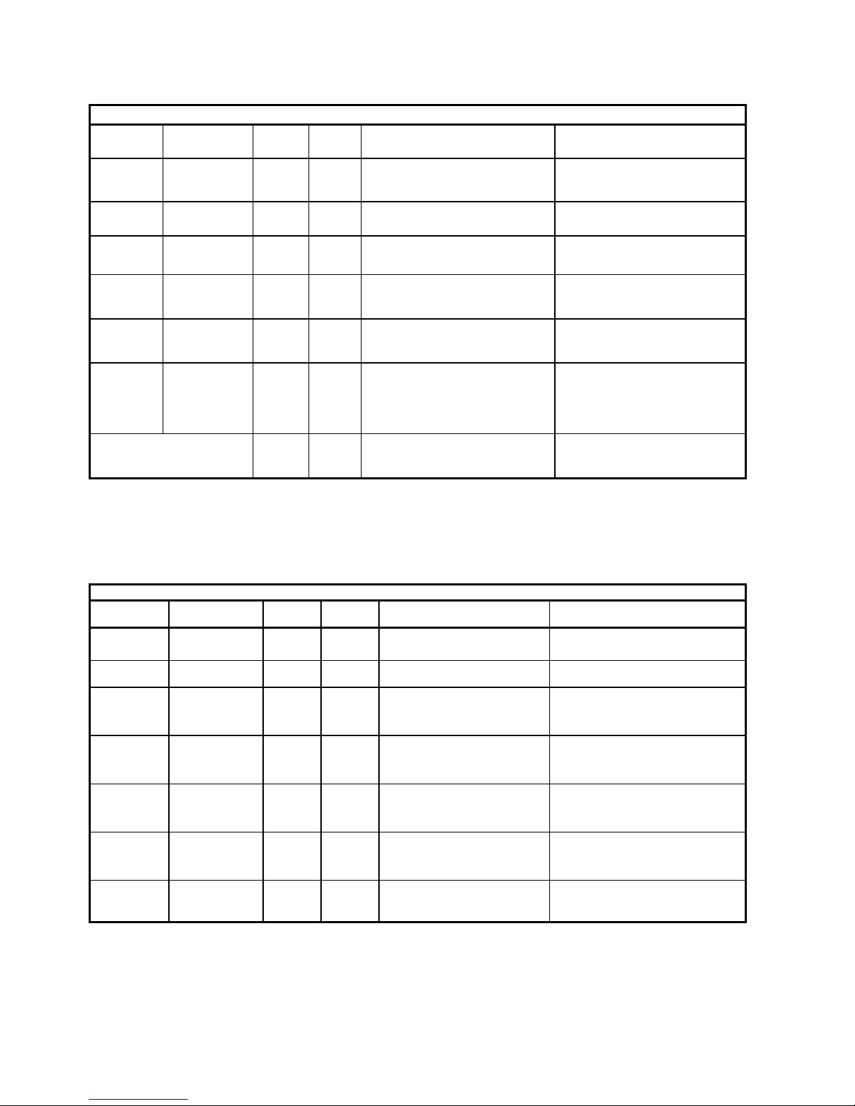
C.3.3) MESSAGES
The system provides 2 types of messages:
System messages: they are fixed and can not be changed by the user.
User-recordable messages: they are 6 and are associated with specific functions.
For optimal management of the system the length of the messages must be calculated in advan-
ce and programmed before each recording.
To record a message, follow the instruction below:
1. Select the number of MICRO TSA 4.0 and at the answer type *key (asterisk)
2. Enter any password
3. Enter the character # (pound) key to enter programming
4. Enter the code of the message you want to register as follows:
5. 11 30 * 08 *where:
11 write access parameters
30 Code of the message you want to register (for example, "Location")
*Start value
08 estimated duration of the message of 8 seconds
*End of value
6. The system reply with the message: "Record after the tone ... ... ...beep"
7. Speak clearly into the microphone of the handset
8. After the programmed time, the system will reply: "Message recorded"
9. To listen to the message, type 12 followed by the code of the recorded messa-
ge. Example 12 30 play the Location message.
10. If you are not satisfied with the result, repeat the procedure from step 4.
NOTE: In case of noisy or bad quality recording, power the MICRO TSA 4.0 from a battery or
agood efficient power supply and use a good quality.
PAR. VALUE DEFAULT MESSAGE NOTE
30 00 or
02 - 20 00 = Parameter not programmed 02 - 20 = Identification
message
Value from 02
to .. = duration of
the message in
seconds
31 02 - 20
Please, stay calm Your request for assistan-
ce has been directed to the permanent call
center.
You ‘re shortly been connected to an opera-
tor
Calming message in cabin
35 02 - 15 Person entraped in the cabin. Main Allarm to the phone
line
Message Presentation Location Motive Instruction
Type of
message
System
(not recordable)
User
(recordable)
User
(recordable only for main
alarm)
System
(test, battery, end of
alarm, ecc)
System
(not recordable)
Example 1:
Messagge
provided
Micr TSA system
(followed by the
digits of the code
configured in par.
04)
Elevator n° 5, at 32 in
London Bridge Street
Person entraped in the
cabin
Press 5 to enter in
communication…..
14
C.3.4) TEST CALL
C.3.5) - BATTERY ALARM
Routine call (test)
PARA-
METRO VALORE De-
fault
Vs
Valori FUNZIONE NOTE
88 Max 20
digits - - Telephone number
40 0 - 9 2N° loops 0 = Infinite
41 01 - 99 03 Time between 2 calls In days
42 00 - 23 00 Waiting time for the next call
(HH + MM) In Hours
43 00 - 59 10 Waiting time for the next call
(HH + MM) In Minutes
44 0 / 1 0Calling mode
0 = Voice call
1 = CLI call (see sect. C.3.9)
Fixed 3- Time between a failed call
and the next one Minutes.
ALLARME BATTERIA
PARAME-
TRO VALORE De-
fault
Vs
Valori FUNZIONE NOTE
89 Max 20
digits - - Telephone number
50 from 0 to 9 2N° loops 0 = infinite
51 from 100
to 150 110 Intervention threshold
voltage
In tenths of VOLT (+/- 0,1V)
Example: 105 = 10,5 Vcc
52 from 00 to
99 01 Intervention threshold
monitoring time In minutes
53 from 01 to
99 01 Time between two calls.
with persistent alarm
In hours
54 from 0 to 1 0Ways of alert
0 = Vocal call
1 = Call in CLI mode (see
section C.3.9)
Fixed Fixed 3- Time between 2 failed
calls In Minutes

15
C.3.7) OPEN COLLECTOR OUTPUT
Note: Reading parameters 70 and 71, besides being played the value of the parameter, is also provided
the state of the relay (On or Off).
RELAYS
PARA-
METER VALUE De-
fault
Yr
Values FUNCTION NOTES
70 0 - 9 7
PIN3 CN2
OUTPUT
(alarm sent)
0-5 used for “Telecontrol”
0 = GND output while DTMF presence
1 - 4 = GND output from 1 to 4 seconds
5 = Connected to GND in latched mode:
each pression of digit 1 change the state of
the output
6 - 9 used for “Alarm sent”:
6 = Activated to GND until the manage-
ment of “End of Alarm”
7 = Activated to GND until confirmation of
the call by pressing digit 5
8 = Activated intermittently until manage-
ment of the “End of Alarm”
9 = Activated intermittently until confirma-
tion of the call by digit 5
71 0 - 6 6
PIN3 CN2
OUTPUT
(alarm recei-
ved)
0-5 used for “Telecontrol”
0 = GND output while DTMF presence
1 - 4 = GND output from 1 to 4 seconds
5 = Connected to GND in latched mode:
each pression of digit 2 change the state of
the output
6 used for “Alarm sent”:
6 = Activated to GND for the time program-
med in parameter 72, starting from attesta-
tion of the call by pressing digit 5 .
72 001 -
999 010 Timeout
output 2
In Seconds.
Activation time of the output 2, if program-
med parameter 71=6

16
C.3.7.1) "Alarm sent” and “Alarm received”"
The two reports ouput of the MICRO TSA 4.0 system, properly programmed, can better manage
light signals and / or Sound for Alarm Received and Sent.
Alarm Sent
When you start a main alarm procedure, the ouput 1, if programmed, activates the signal "alarm
sent"
The alert remains active until acknowledged or to receive alarms or to the management of
the End of alarm.
Alarm Received
With the ouput 2, suitably programmed, you can manage the received alarm signal, remaining
active from the confirm of the alarm call (key 5), to the end of programmed time.
C.3.8) TELEPHONE NUMBERS
The system MICRO TSA 4.0 maintains an address book of 8 telephone numbers
(parameters from '80 to 91) and each one can be associated with aspecific
event or alarm signaling. The alarm has 5 main numbers that are dialed in cyclic mode until it
receives confirmation code (digit 5 by an operator) or until the end of the programmed cycles.
To make easy the programming of telephone numbers, when all calls are forwarded to a sin-
gle number, you can use the parameter 99.
To delete a number from the phone book simply set a schedule with its parameter, empty.
To change a programmed number just overwrite it.
RUBRICA TELEFONICA
PAR. VAL. FUNZIONE VOSTRO NUMERO
80
Max
20
cifre
End of alarm (*)
81 1° tel n° main alarm and maintainers(*)
82 2° tel n° main alarm and maintainers
83 3° tel n° main alarm and maintainers
84 4° tel n° main alarm and maintainers
85 5° tel n° main alarm and maintainers
88 Test call (*)
89 Battery alarm (*)
99
With this program you can set or delete all
phonebook entries, marked with an aste-
risk (*), with a single programming

17
C.3.9) CLI CALLS
The system performs the alarm with CLI mode, to the following steps:
call the phone number programmed and, if it is free after 2 rings (about 10 seconds) discon-
nect.
if the number dialed is busy, the system retries the selection every 3 minutes until it will be
free, however at most, the number of cycles set for the type of alarm.
C.3.10) COMMUNICATION CODES
The system MICRO TSA 4.0 communicate with a call center via DTMF or “Ademco Contact ID”
protocol.
To select the protocol program the parameter 11 (see Section C.3.1).
Example: to select the mode 2, program 11 11 * 2 *
Note: in Ademco mode, is still possible to answer in voice mode and listening to
the message location with the digit 7, and then, enter in conversation with the cab with the digit 5,
and close with the digit 9.
Type of call
CODICE
TONI DTMF
MODO 1
MODO 3 ADEMCO
Event Group Zone
Main Alarm *01 140 00 001
Battery alarm *07 302 00 000
End of alarm *20 300 00 000
Routine call (test) *05 602 00 000
Inbound call *31 000 00 000

18
C.4) ERRORS
In the error condition, indicated by the quick flashing of the red LED on board and the output 1, if
you enter into communication with MICRO TSA 4.0 from a remote phone, you can hear the error
message.
The errors found are:
- missing of a number stored for the alarm (parameters 81 to 85)
- Supply voltage below 10 VDC
- Telephone line not detected: PSTN, extention of PBX or GSM gateways, the check of the line
is a programmable function.
During the error condition, except of course for the absence of the line, you can access remotely
to the system to read and write the configuration.
PROBLEM POSSIBLE CAUSE POSSIBLE SOLUTION
The system sometimes doesn’t answer
and/or frequently reset itself
There are
strong electromagnetic
pulses caused
by power
equipment that disturbs
the MICRO TSA 4.0.
For proper operation it is advisable to
install the MICRO TSA 4.0 at least
2meters from any source of
electromagnetic
disturbances: switchgear,
motors,power relays,
inverters, etc.. and use for
links, new cables and dedicated.
The system is on but does not
handle the alarms.
The red LED flashes quickly (like
the green led).
The system is in
ERROR. See indication section C.4
He has difficulty in properly
receive DTMFremote.
Disturbed or low audio
signal
Don’t enter the DTMF tones system is
playing audio messages and wait at
least a second between digits.
Call the MICRO TSA 4.0 from a site
with low ambient noise.
Check for proper power supply.
If the MICRO TSA 4.0 is
connected to a GSM gateway instead
of the analog trunk,make sure that
the GSM signal is good and
possibly move the GSM device in a
place that guarantees a good signal,
make sure that the antenna and
the GSM device is at least 1
meter away from the MICRO TSA 4.0.
Opening the hands-
free communication between
the cabin and the
intercom handset, you hear a "whistle".
Handsfree volume too
loud
Lower the volume of the speaker and
adjust optimally.
Check the corrispondence of the
microphone hole on the panel.
The recording quality is not
good messages customizable (you can
hear a buzz).
Power supply
not suitable or noise on
telephone line.
Use a good quality power
supply. If you are using a GSM
gateway, make sure the MICRO TSA
4.0 is at a distance of at least 1
meter from the antenna.

19
WARRANTY
Teledif Italia warrants this product free from manufacturing defects for 2 (two) years from date of
purchase.
The date of purchase will result from the receipt or invoice.
During the warranty period the equipment will be replaced or repaired free in the laboratories
of Teledif Italia in Turin.
The cost of transport to and from the laboratory Teledif Italia is always charged to the customer.
The equipment to be repaired under warranty must be submitted toTeledif Italia in its original
packaging and always accompanied by a copy of the purchase.
Failure to follow the instructions for use, the use of power other than that indicated, the assembly
of non-original parts, repairs by unauthorized third parties, altering or removing the serial num-
ber and any tampering,void the warranty.
Nothing will be due to the buyer for inactivity time unit, or he may claim damages or compensa-
tion of expenses for any direct or indirect arisingfrom use of this.
For every problem it is advisable to contact the installer or prior to the store where you purcha-
sed the unit.
Any dispute will be brought before the courts of Turin.
DISPOSAL
This product is not within normal MSW (Municipal Solid Waste) as it is
composed primarily of electronic components. The symbol of the bin withwheels marked
with a cross indicates that the disposal must be made through approved facilities in
accordance with DL 151 of July 25, 2005.One of improper disposal of the equipment
or parts thereof, may cause harmful effects to human health and the environment.
Prior to disposal, remove any batteries and dispose of separately in accordance with Legislative
ROHS
The electronic circuit of this product is designed and manufactured in accordance with
the provisions of legislation 2002/CE (RoHS)
COMPLIANCE
Teledif Italia declares that the device meets the directives by the Councilin respect
of EMC Directive 2004/108/EC and electrical safetyequipment for low volta-
ge Directive 2006/95/EC and its subsequentchanges. The conformity of the product is
expressed by the "CE".
PRECAUTIONS FOR USE
Before attempting any cleaning or maintenance, disconnect the unit from the mains and
any other connection.
Do not put in contact with liquid and do not use aerosol sprays or solvents for cleaning.
Use and / or store the product under conditions of temperature andhumidity ranges (see p. 2)..
Food product with the supply voltages listed in this manual.
For any repairs, contact your dealer or service center Teledife Italy.

20
TELEDIF ITALIA S.R.L.
Via Reiss Romoli 194 - 10148 TORINO - Italy
Tel.: 011.70.70.707 Fax: 011.19.82.49.13
Certified UNI EN ISO 9001:2008 Reg. n° ER/ES-1072/2002
Table of contents


 user manual")


