Page 16
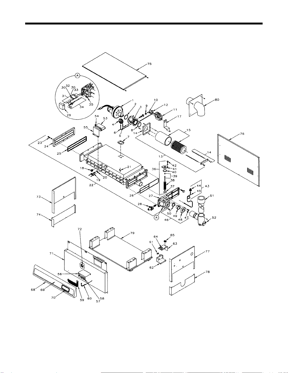
Item Description Part Number
22. Burner/Heat Exchanger Assy................... R0204200
23. Bolt/Washer Set, Header ......................... R0205900
24. Header, Return......................................... R0202200
25. Gasket, Return Header............................ R0201200
26. Gasket, In/Out Header..............................R0201100
27. Header, In/Out ......................................... R0202600
28. Pressure Relief Pressure ......................... R0200000
29. Cover, High Limits ................................... R0201700
30. Retainer, High Limits ............................... R0207800
31. Harness Assembly, High Limits............... R0208000
32. High Limit, 150°F..................................... R0023000
33. High Limit, 135°F..................................... R0022700
34. Sensor Assy., Temperature...................... R0208100
35. Drain Cock/Plug Kit ................................. R0010500
36. Flow Control Assembly............................ R0208200
37. Disc, Flow Control ....................................R0011500
38. Spring, Compression, Green................... R0202000
39. Rod/Nut Set, Flow control ....................... R0206100
40. Gasket, Flow Control ................................R0011400
41. Cap, Flow Control.....................................10557400
42. Bolt/Washer Set, Flow Cntrl Cap ............ R0206000
43. Water Pressure Switch Assy. .................. R0200300
44. Water Pressure Switch ............................ R0095100
45. Siphon Loop, Water Press. Sw................ R0208300
46. Flange Assembly ..................................... R0055000
47. Bolt/Washer Set, Flange...........................R0211200
48. Flange, 2 Inches ....................................... 10573500
49. Sleeve, Flange , 2 Inches .........................S0078200
50. Gasket, 1-1/2 Inches Pipe Adapter ..........S0078100
51. Vent Stack Assembly............................... R0203100
52. Vent Adapter Assembly ........................... R0202800
53. Ignition Control ........................................ R0202900
54. Fusible Link.............................................. R0012200
55. Bracket, Ignition Control .......................... R0209100
56. Temperature Control Assembly ................R0211300
57. Knob/Temp-Lok Set ..................................R0211400
58. Label, Temperature Control ......................R0211600
59. 8-Pin Harness Assembly ......................... R0212300
60. 3-Pin Harness Assembly ......................... R0212400
61. Lug, Neutral ..............................................E0106800
62. Junction Box, Bottom .............................. R0209500
63. Junction Box, Top .................................... R0209600
64. Transformer, 120/24 VAC ........................ R0200800
65. Terminal Strip Assembly.......................... R0209700
66. Fuse Assembly ........................................ R0212600
67. Fuse, 1 1/4 Amp. ..................................... R0021300
68. Panel, Upper Front .................................. R0205100
69. Label, Upper Front Panel ........................ R0209800
70. Bezel, Temperature Control ..................... R0209900
71. Panel, Lower Front .................................. R0210000
72. Glass, Sight ..............................................F0038700
73. Panel, Upper Left Side............................. R0210100
74. Panel, Lower Left Side............................. R0210200
75. Panel, Top ................................................ R0210300
76. Panel, Rear .............................................. R0210400
77. Panel, Upper Right Side .......................... R0210500
78. Panel, Lower Right Side .......................... R0210700
79. Base Assembly ........................................ R0210800
80. Vent Termination* ..................................... 10685600
*Required for Indoor Installations
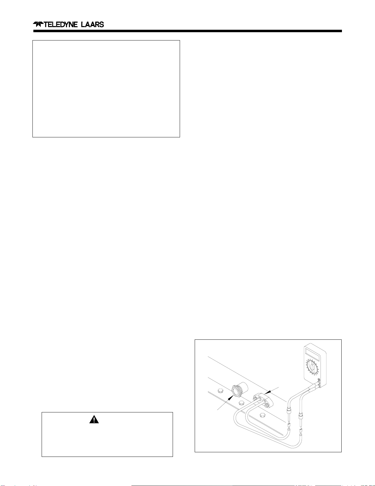
Figure 16. Igniter Installation
After eliminating all possible problems with the
fuel supply and igniter, replace the ignition control.
SECTION 5.
Parts List for Hi-E EPH 300
5A. General Information
To order or purchase parts for the Teledyne Laars
Hi-E EPH 300 pool and spa heater, contact your nearest
Teledyne Laars dealer or distributor. If they cannot
supply you with what you need, contact Customer
Service, Teledyne Laars, 6000 Condor Drive, Moorpark,
CA 93021, telephone (805) 529-2000.
5B. Parts List
Item Description Part Number
1. Fan, Combustion ..................................... R0204700
2. O-Ring, Venturi ........................................ R0205400
3. Venturi...................................................... R0015700
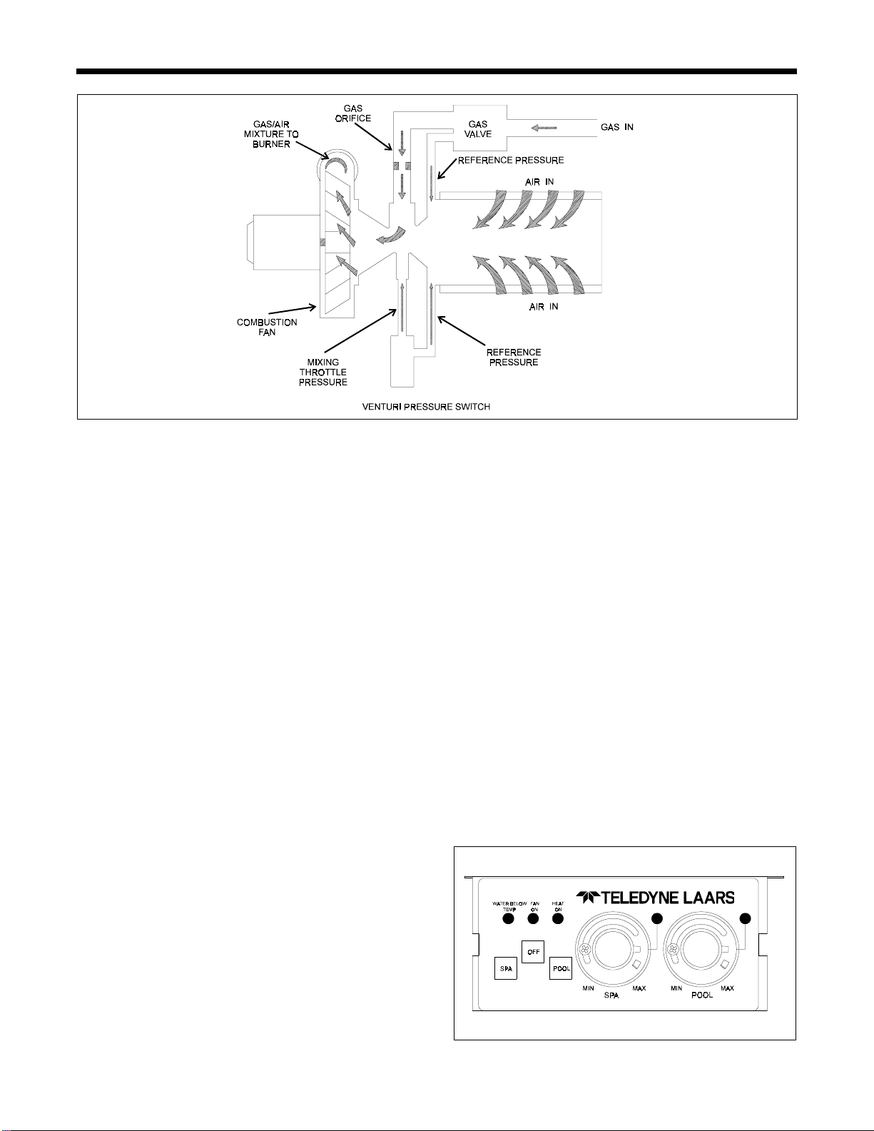
4. Venturi Pressure Switch........................... R0203300
5. Tube, Venturi Press. Sw., Throat............. R0202300
6. Tube, Venturi Press. Sw., Filter ............... R0202500
7. Gasket, Combustion Fan......................... R0205500
8. Plug, Pressure Test Point ........................ R0204800
9. Nipple, Gas Orifice .................................. R0205600
10. Orifice
Natural Gas ............................................. R0205700
LP Gas ..................................................... R0205800
11. Valve, Gas ............................................... R0200100
12. Tube, Venturi Press. Sw., Valve............... R0202500
13. Filter Assembly ........................................ R0204500
14. Filter Support, Kit..................................... R0206200
15. Filter, Air................................................... R0201800
16. Harness, Combustion Fan....................... R0206700
17. Bracket, Gas Valve .................................. R0210900
18. View Port Nipple ...................................... R0201500
19. Igniter Assembly ...................................... R0016400
20. Gasket, Igniter ......................................... R0205300
21. Connector, Wire........................................E0092000