Teledyne Lecroy PP026 Series User manual

PP026-1
PP026-2
User Manual
PP026
Passive Probe

700 Chestnut Ridge Road
Chestnut Ridge, NY, 10977-6499
Tel: (845) 425-2000, Fax: (845) 578 5985
teledynelecroy.com
PP026 Passive Probe Instruction Manual
© 2020 Teledyne LeCroy, Inc. All rights reserved.
Users are permitted to duplicate and distribute Teledyne LeCroy documentation
for internal training purposes only. Resale or unauthorized duplication of
Teledyne LeCroy documentation materials is strictly prohibited.
Information contained herein is classified as EAR99 under the U.S. Export
Administration Regulations. Export, reexport or diversion contrary to U.S. law is
prohibited.
Teledyne LeCroy is a registered trademark of Teledyne LeCroy, Inc. Other product
or brand names are trademarks or requested trademarks of their respective
holders. Information in this publication supersedes all earlier versions.
Specifications are subject to change without notice.
933095-00 Rev A
pp026-user-manual.pdf
November, 2020

User Manual
EAR99 technology subject to restrictions on copyrights page. 1
Terms and Symbols
The following symbols appear on the product or in its documentation:
WARNING
High Voltage. Risk of electric shock or burn.
WARNING or
CAUTION
Condition or practice could result in injury or loss
of life, or damage to equipment.
DOUBLE INSULATION
PROTECTIVE (EARTH) TERMINAL
Introduction
Teledyne LeCroy PP026 is a passive high impedance voltage oscilloscope
probe designed and calibrated for use with general purpose oscilloscopes
having an input impedance of 1 MΩ and can be compensated for use with
instruments having an input capacitance between 10 and 20 pF. It is
compatible with oscilloscopes that automatically detect probe attenuation
and adjust their readout accordingly.
To avoid electric shock, keep fingers behind the probe’s finger
guard during use.
Rated for indoor use only. Do not operate where conductive
pollutants may be present.

PP026 Passive Probe
2 EAR99 technology subject to restrictions on copyrights page.
Specifications
Model Attn.
Input
Impedance B/W
Rise
Time Length
Compensation
Range
R (MΩ) C (pF) (MHz) (ps) (m) (pF)
PP026
10x 10 10 500 700 1.3 10 - 20
Attenuation Ratio ......... 10:1 ± 1%
Max. Input Voltage....... Circuits not directly connected to Mains: 500 Vrms,
.........................................1500 V transient overvoltage
.........................................Measurement Category II*: 400 Vrms
To reduce risk of fire or electric shock, do not exceed the voltage or
category ratings of the probe. See voltage derating curve on p.3.
Pollution Degree ........... Pollution Degree 2*
Operating Altitude ................. Up to 3000 meters
Max. Operating Temp.. 0° C to +50° C
Humidity......................... 5% to 95% RH (10 to 30 °C)
.........................................5% to 75% RH (30 to 40 °C)
.........................................5% to 50% RH (above 40 °C)
.........................................RH not controlled below 10 °C
* As defined in IEC/EN 61010-031. See definitions below.
Definitions
Measurement Category II (CAT II) refers to measurements performed on circuits directly connected to
utilization points (socket outlets and similar) of the low-voltage mains installation.
Pollution Degree 2 refers to an operation environment where normally only dry non-conductive
pollution occurs. Temporary conductivity caused by condensation should be expected.

User Manual
EAR99 technology subject to restrictions on copyrights page. 3
PP026 Input Impedance Profile
Voltage vs. Frequency Derating Curve

PP026 Passive Probe
4 EAR99 technology subject to restrictions on copyrights page.
EC Declaration of Conformity
The product conforms to the applicable European Union
requirements per Low Voltage Directive (LVD) 2014/35/EU.
Compliance was demonstrated to the following specification as
listed in the Official Journal of the European Communities:
IEC/EN 61010-031:2015 Safety requirements for electrical equipment for
measurement, control and laboratory use – Part 031: Safety requirements for
handheld probe assemblies for electrical measurement and test.
EU RoHS2 Compliance
The probe and accessories conform to the 2011/65/EU RoHS2 Directive,
inclusive of any modifications of said Directive.
Disposal
The probe complies with the applicable European Union
requirements to Directives 2012/19/EU on Waste Electrical and
Electronic Equipment (WEEE).

User Manual
EAR99 technology subject to restrictions on copyrights page. 5
General Safety Information
Observe generally accepted safety procedures in addition to those
listed here to avoid personal injury or damage to equipment. The
overall safety of any system incorporating this accessory is the
responsibility of the assembler of the system.
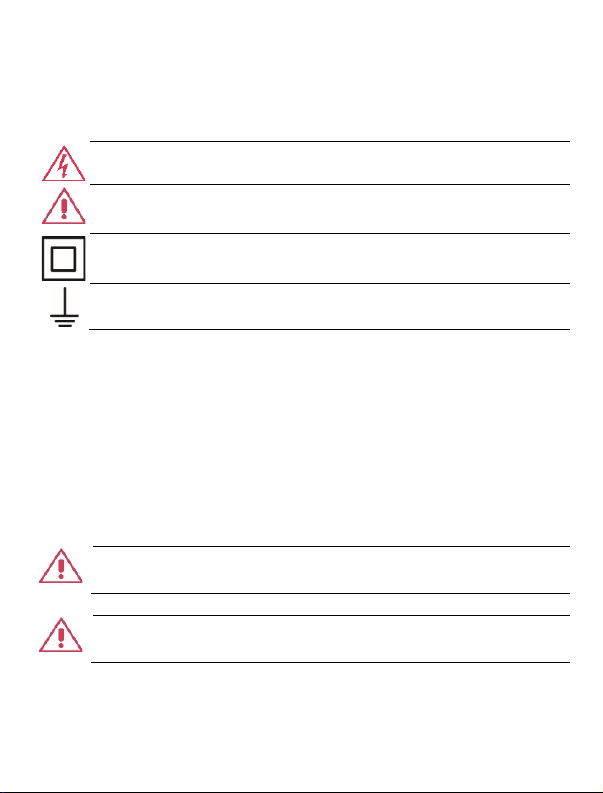
Connect only to grounded instruments. Use only with compatible Teledyne
LeCroy oscilloscopes that have their BNC input connected to an earth
ground. Do not connect the probe reference lead to any point which is at a
potential other than earth ground.
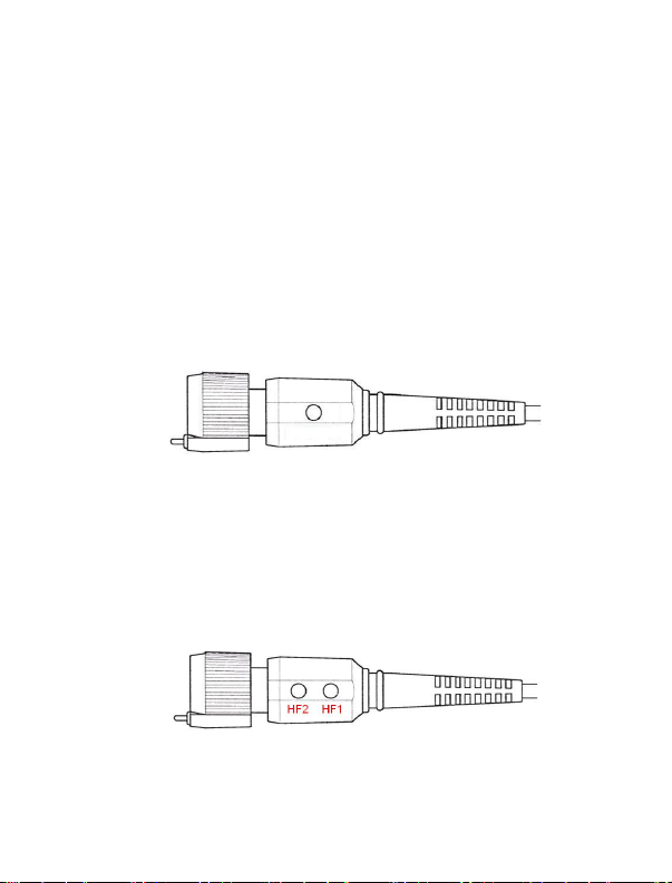
Connect and disconnect properly. Connect probe to the oscilloscope before
connecting it to the test circuit. Disconnect the probe input and reference
lead from the test circuit before disconnecting from the oscilloscope. Do
not connect/disconnect probes while connected to a voltage source.
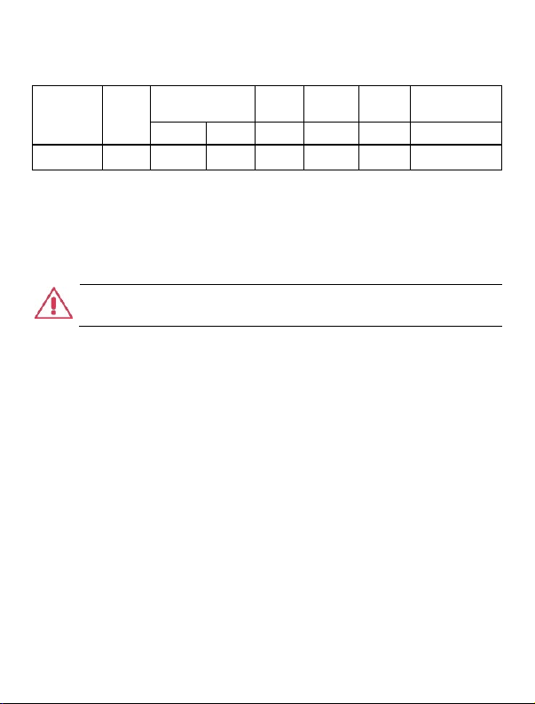
Do not overload. Do not apply any potential to the probe leads that exceeds
the maximum rating of the probe. Observe all terminal ratings on the
oscilloscope before connecting. Consult the oscilloscope product manual
for further ratings information.
Always comply with the Voltage vs. Frequency Derating Curve.
Do not remove probe casing. Touching exposed connections may result in
electric shock.
Use indoors only within operational environment listed. Do not use in wet or
explosive atmospheres. Keep product surfaces clean and dry.
Handle with care. Probe tips are extremely sharp and may puncture skin or
cause other bodily injury if not handled properly.
Keep fingers behind the finger guard of probe body and accessories.

PP026 Passive Probe
6 EAR99 technology subject to restrictions on copyrights page.
Do not operate with suspected failures. Before each use, inspect the probe
and accessories for any potential damage such as tears or other defects in
the probe body, cable jacket, accessories, etc. If any part is damaged, cease
operation immediately and sequester the probe from inadvertent use.
Cleaning
•Clean only the exterior of the probe, cables, and accessories. Use a
soft cotton cloth moistened with a mild detergent and water solution.
Do not allow any portion of the probe to be submerged at any time.
•Dry the probe and accessory thoroughly before attempting to make
any voltage measurement.
•Do not subject the probe to solvents or solvent fumes as these can
cause deterioration of the probe body, cables, and accessories.
Service
Refer all repairs to qualified service personnel. Contact Teledyne LeCroy at
the following address to arrange to return the probe for service:
Teledyne LeCroy, Inc.
700 Chestnut Ridge Road
Chestnut Ridge, NY, 10977-6499
Ph: 800-553-2769 or 845-425-2000
Fax: 845-578-5985
contact.cor[email protected]
For the most complete and up-to-date list of sales and service centers by
country, visit teledynelecroy.com/support/contact.

User Manual
EAR99 technology subject to restrictions on copyrights page. 7
Probe Compensation
Proper compensation of the probe is required to assure amplitude accuracy
of the waveform being measured by matching the probe to the
oscilloscope’s input capacitance. Compensation should be adjusted
whenever the probe is connected to or transferred between oscilloscopes.
Low Frequency
1. Apply a 1 kHz square wave to the probe or connect to the
oscilloscope’s calibrator output.
2. Adjust the single LF trimmer located on the PP026 BNC
Compensation Box until you achieve a flat-topped square wave.
High Frequency
1. Apply a 1 MHz square wave to the probe (< 0.7 ns rise-time).
2. Remove the plastic caps from the two, HF trimmers on the PP026
BNC Compensation Box.
3. Adjust HF2 then HF1 until you achieve a flat-topped square wave.

PP026 Passive Probe
8 EAR99 technology subject to restrictions on copyrights page.
Over-compensated, correct, and under-compensated waveforms
Probe Accessories
Probe Tips
Both the rigid probe tip and the spring tip can be screwed on to the probe
body by hand.
Be sure not to overtighten the tips to avoid damaging the threads.
Ground Accessories
The ground lead and the short collar are attached to the probe at the time
of shipping. To replace the ground lead with the swivel lead adapter,
unscrew the short collar from the probe and remove the ground lead.
Replace the short collar to hold the swivel lead adapter in place.
Alternatively, the long collar can be pushed onto the probe body and used in
conjunction with the ground spring, BNC adapter or PCB adapter.

User Manual
EAR99 technology subject to restrictions on copyrights page. 9
Replaceable Parts
Item
Part Number
Description
Quantit
y
1
PK6-5MM-101
Rigid Probe Tip (1 installed standard)
2
2
PK5-PK6-001
Trimmer Tool
1
3
PK6-5MM-102
Sprung Hook
1
4
PK5-PK6-002
Color Coding Rings (2 ea. yellow, red, green, blue)
8
5
PK6-5MM-103
Ground Lead with Alligator Clip
1
6
PK6-5MM-104
Ground Spring
1
7
PK6-5MM-105
PCB Adapter
1
8
PK6-5MM-106
BNC Adapter 5mm
1
9
PK6-5MM-107
Spring Tip
1
10
PK6-5MM-108
Probe Tip Cover
1
11
PK6-5MM-109
IC Tip Insulators
2
12
PK6-5MM-110
Tip Insulator
1
Standard Accessory Replacement Kit part number is PKIT6-5MM-101.

PP026 Passive Probe
10 EAR99 technology subject to restrictions on copyrights page.
Warranty
NOTE: THE WARRANTY BELOW REPLACES ALL OTHER WARRANTIES,
EXPRESSED OR IMPLIED, INCLUDING BUT NOT LIMITED TO ANY IMPLIED
WARRANTY OF MERCHANTABILITY, FITNESS, OR ADEQUACY FOR ANY
PARTICULAR PURPOSE OR USE. TELEDYNE LECROY SHALL NOT BE LIABLE FOR
ANY SPECIAL, INCIDENTAL, OR CONSEQUENTIAL DAMAGES, WHETHER IN
CONTRACT OR OTHERWISE. THE CUSTOMER IS RESPONSIBLE FOR THE
TRANSPORTATION AND INSURANCE CHARGES FOR THE RETURN OF PRODUCTS
TO THE SERVICE FACILITY. TELEDYNE LECROY WILL RETURN ALL PRODUCTS
UNDER WARRANTY WITH TRANSPORT PREPAID.
Teledyne LeCroy warrants this oscilloscope accessory for normal use and
operation within specification for a period of one year from the date of shipment.
Spare parts, replacement parts and repairs are warranted for 90 days.
In exercising its warranty, Teledyne LeCroy, at its option, will either repair or replace
any assembly returned within the warranty period to the Customer Service
Department of an authorized service center. However, this will be done only if the
product is determined by Teledyne LeCroy’s examination to be defective because of
workmanship or materials, and the defect is not caused by misuse, neglect,
accident, abnormal conditions of operation; or, damaged by attempted repair or
modifications by a non-authorized service facility.
The customer will be responsible for the transportation and insurance charges for
the return of products to the service facility. Teledyne LeCroy will return all products
under warranty with transportation charges prepaid.
This warranty replaces all other warranties, expressed or implied, including, but not
limited to, any implied warranty of merchantability, fitness, or adequacy for any
particular purposes or use. Teledyne LeCroy shall not be liable for any special,
incidental, or consequential damages, whether in contract or otherwise.
933095-00 Rev A
November, 2020
This manual suits for next models
1
Table of contents
Other Teledyne Lecroy Analytical Instrument manuals
Popular Analytical Instrument manuals by other brands

TOOLCRAFT
TOOLCRAFT 1433978 operating instructions

SPX
SPX Radiodetection Pearpoint P571 Flexicoiler Operation manual

Responsive Respiratory
Responsive Respiratory Respond O2 Operation manual

Leica
Leica DISTO D210 user manual

Smith-Root
Smith-Root Apex quick start guide

Precaster
Precaster HT60 Operation manual