Teledyne Lecroy Summit T54 User manual

PCI Express®5.0 Slot Interposer
User Manual and Quick Start Guide
Components
The interposer package includes the following components:
• PCI Express 5.0 Slot Interposer
• Half height bracket
• Four spare screws for bracket attachment
• DC Power Adapter (12 volts)
• User Manual and Quick Start Guide (this document)
Inspect the received shipping container for any damage. Unpack the container and account for each of the system
components listed on the accompanying packing list. Visually inspect each component for absence of damage.
In the event of damage, notify the shipper and Teledyne LeCroy. Retain all shipping materials for shipper’s inspection.
Introduction
Use this document for quick installation and setup.
The Teledyne LeCroy PCI Express 5.0 Slot Interposer plugs in to a PCIe®CEM Connector and allows you to probe PCI
Express traffic between a host and a PCIe expansion card. The interposer assures reliable data transmission while providing
100% capture of all data traffic flowing through the PCIe slot interface. Connecting the interposer to a Teledyne LeCroy
analyzer allows decoding and display of data flowing in both directions and across all lanes, and will display data traffic using
the industry-standard CATC Trace™ data display, along with a wide range of traffic and error reports. The Gen5 Interposer
is for use with a Summit T5 Gen5 capable analyzer. The interposer uses Teledyne LeCroy’s T.A.P.5 technology to ensure
complete data capture at Gen5 rates with minimal signal perturbation.
The Gen5 Interposer supports data rates of 2.5 GT/s, 5.0 GT/s, 8.0 GT/s, 16.0 GT/s or 32.0 GT/s and depending on the
version purchased link widths up to x16. For all the versions of the interposer, the PCIe connector on the card will support
PCIe expansion cards up to x16. Versions of the interposer with lower link width have a reduced PCIe edge connector at the
bottom. A x1, x4, x8 or x16 DUT card can be inserted on the top connector and the connection will automatically negotiate
to the lesser link width. The image below shows a Gen5 x8 Interposer, other versions include: x1, x4 and x16.
PCI Express 5.0 Slot Interposer
1
2

Cables
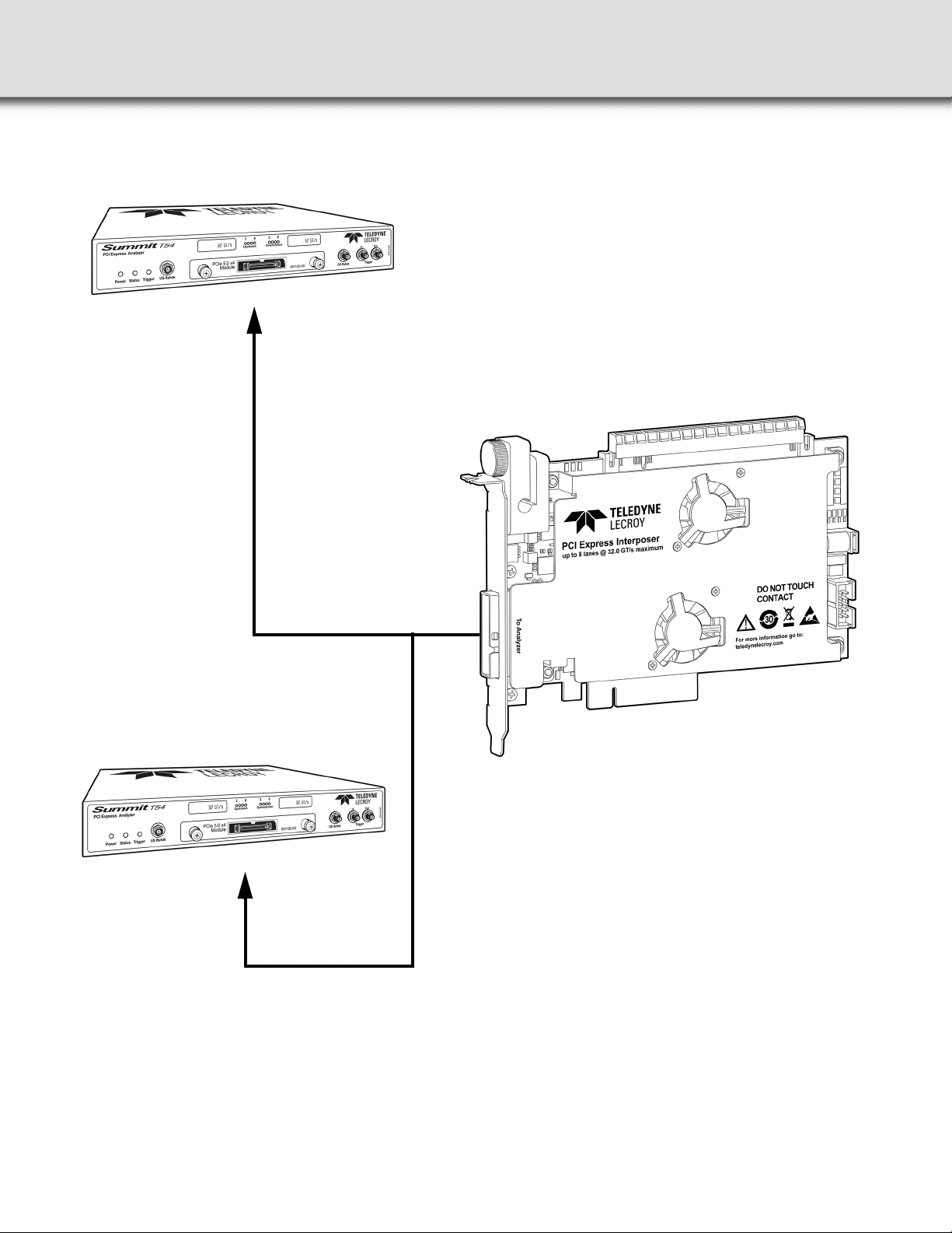
The Gen5 interposer is connected to the Summit T5 by means of proprietary high speed serial cables.
The straight cable allows the connection of a single interposer to a Summit T5 analyzer and leverages the full buffer for
recording bus activity in a single bus, this cable can be used with x1, x4, x8 or x16 interposers. Other cable configurations
are discussed in the Gen5 Cables User Manual and Quick Start Guide including:
• Gen5 x4 Straight Cable (PE027UCA-X) shown below
• Gen5 x8 Y Cable for Summit T54s in Expanded Mode (PE028UCA-X)
• Gen4 to Gen5 Straight x4 Conversion Cable (PE030UCA-X)
Gen5 x4 Straight cable (PE027UCA-X)
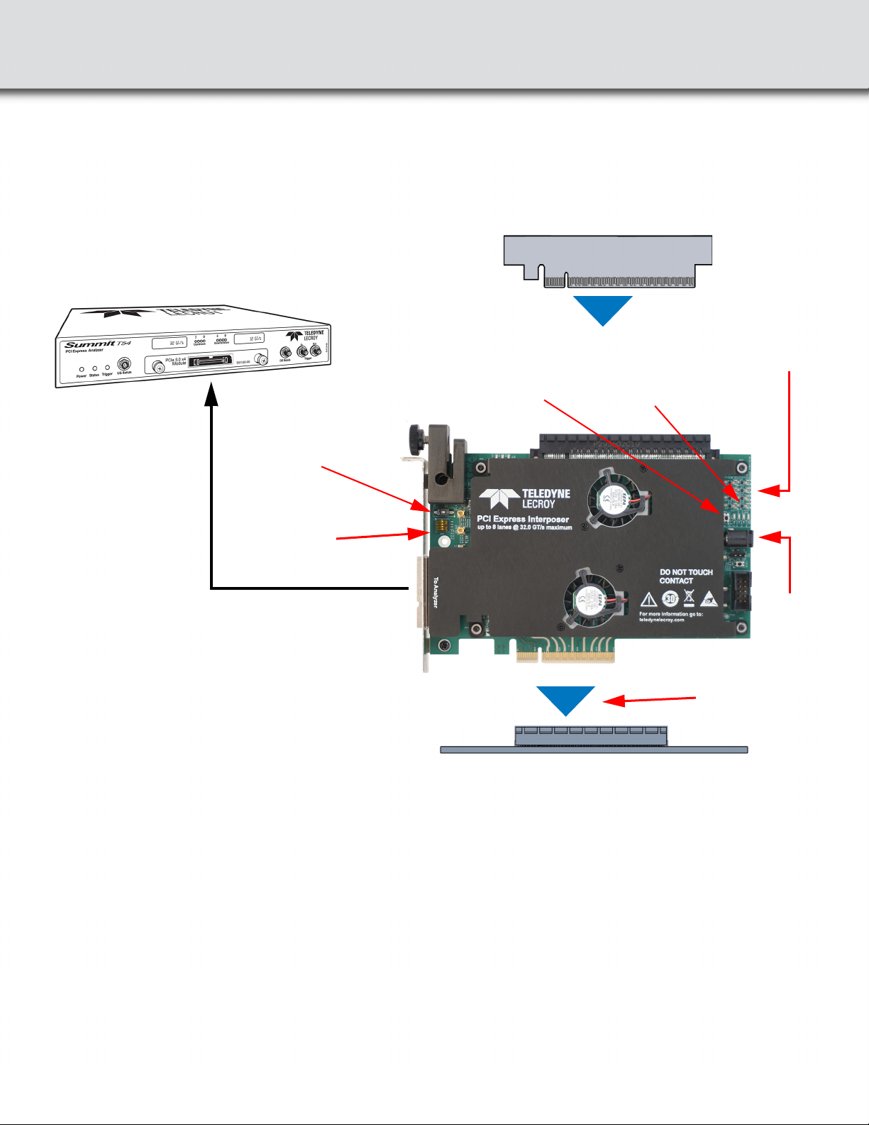
Connections
Perform to the following steps to connect the Interposer (see the image below):
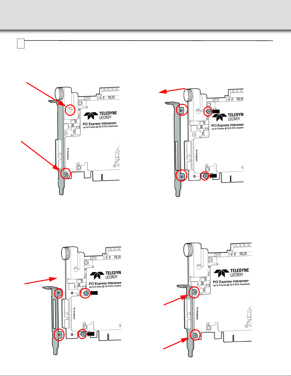
Warning: The interposer has a bracket that can be secured to a chassis to provide stability. Always secure the interposer
properly to a chassis otherwise the interposer (and your equipment) could be damaged and warranties voided.
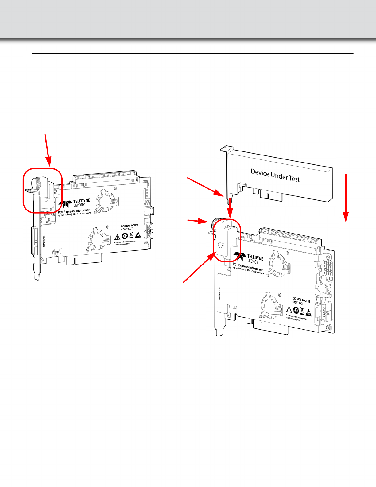
1. Install the Interposer into the host system under test PCIe CEM slot connector.
2. Install the PCIe expansion card under test (DUT) into the top connector on the interposer. When plugging in a device
with any supported link width (x1, x2, x4, x8 or x16), the devices will negotiate to a lesser common link width between
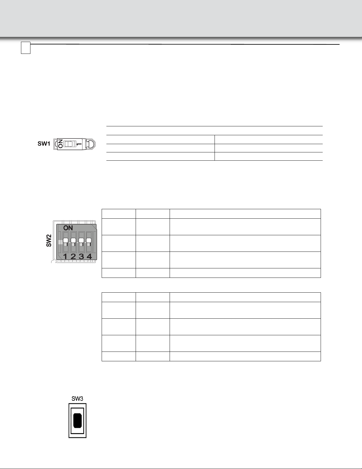
the PCIe plug in card and the selected active lanes by SW3 discussed in Section “5” on page v.
3. Connect 12V DC using the AC adapter supplied with the interposer. Make sure that the AC adapter is turned on.
4. Connect the Gen5 interposer to a Summit T5 analyzer using the selected cable (PE027UCA-X).
5. Connect the compatible Summit analyzer to a host machine using the USB or Ethernet port on the front panel of the
analyzer.
6. Install the PCIe Protocol Analysis on a host machine. This application is needed to control the protocol analyzer.
7. Power ON the analyzer.
8. Start recording with the analyzer.
9. Power ON the host system.
10. Use the Teledyne LeCroy software application to monitor, record and view PCI Express in the PCI expansion card DUT
system.
Note: Steps 7, 8, and 9 are needed in this order for "Power ON" traces.
See Interconnection next page.
3
4

Interconnection Overview with Summit T54 Analyzer
PCIe Card Under Test
12V DC
from
adapter
supplied
Summit T54 Analyzer
(with Gen5 PHY)
Configuration
switches and clock
inputs
(see table below):
SW2
PCIe Slot from Host System Under Test
Depending on the
Interposer, the edge
connector can be
x16, x8, x4 or x1
DUT Power LED
Status Switch: SW1
Active Width Control
Pushbutton: SW3
Signal
Detect
LEDs
AC
BD
Gen5 Straight Cable x4
(PE027UCA-X)
Link Width
Status LEDs
Connection diagram for single port up to x4 using a Gen5 x8 Interposer

Summit T54 Analyzer
(with Gen5 PHY)
Summit T54 Analyzer
(with Gen5 PHY)
PCI Express 5.0 x8 Slot Interposer
Upstream[7:0]
Downstream[7:0]
Gen5 Y Cable x8
(PE028UCA-X)
Connection diagram for single port up to x8 using a Gen5 x8 Interposer
and two Summit T54s in Expanded Mode

Clock Configuration and Other Switch Settings
The source for the reference clock used by the analyzer to record PCI Express traffic is configurable according to below
table for SW2. Make sure clock source in Recording Options in the PCIe Protocol Analysis application is set to External.
Pushbutton SW4 allows the user to change the link width enabled on the interposer by pressing SW4 multiple times.
SW1: DUT Power LED Status
This switch connects the DUT power indication LEDs to the bus power. SW1 is located on the front of the interposer near SW2 and is
configurable according to table below:
SW2: Clock Source Control
Note: Factory settings for all switches are ON.
SW3: Active Width Control Pushbutton
SW1: DUT Power LED Status on Interposer
Selection SW1
LED Connected (Default) ON
LED Disconnected OFF
SW2.1 SW2.2 Reference Clock Source for Downstream Analysis
ON ON Analyzer will be supplied with reference clock from the
Host System PCIe slot connector.
OFF ON Analyzer will be supplied with reference clock from
US_CLK MMCX connector.
ON OFF Analyzer will be supplied with reference clock from
DS_CLK MMCX connector.
OFF OFF No clocks are supplied to the analyzer.
SW2.3 SW2.4 Reference Clock Source for Upstream Analysis
ON ON Analyzer will be supplied with reference clock from the
Host System PCIe slot connector.
OFF ON Analyzer will be supplied with reference clock from
US_CLK MMCX connector.
ON OFF Analyzer will be supplied with reference clock from
DS_CLK MMCX connector.
OFF OFF No clocks are supplied to the analyzer.
Pushbutton SW3 is used to turn off the terminations and remove all loads on the unused interposer
receivers depending on the maximum number of lanes to be analyzed. Press the pushbutton switch
(SW3) to move to the next active width as indicated by the LEDs (next to the switch) on the interposer.
This is useful for devices that require terminations not to be present in order to train to a lower link width.
The Active Width can be also controlled from the PCIe Protocol Analysis.
Note: Even though the Active Width may be lower than x16, it may be possible that the Signal Detect
LEDs for higher lanes are ON if those lanes are transmitting signal.
5
Note: This switch connects the DUT power indication LEDs to the bus power.

DUT Retention Clamp
The Gen5 Interposer comes with a DUT retention clamp installed.
Use the DUT retention clamp to secure the bottom of the DUT’s metal flange. Fully insert the DUT in the top connector of
the interposer. Then use the thumbscrew in the DUT retention clamp to secure the DUT. See the drawings below.
DUT Retention Clamp: Front View DUT Retention Clamp: Rear View
DUT
retention
clamp
DUT
retention
clamp
DUT
retention
clamp
thumbscrew
DUT’s
metal
flange
6

Swapping the Full Height Bracket for the Half Height Bracket
Locate the two screws on the front of the Interposer securing the Full Height Bracket.
Using a Phillips head screw driver, remove the two screws that secure the full height bracket. Save the screws for
installation of the half height bracket. The diagrams below show a x8 Interposer but the same procedure can be used for
any link width Gen5 Interposer (x1, x4 or x16).
Gen5 x8 Interposer with Full Height Bracket: Attached and Removed
Locate the Half height bracket and the two screws from the disassembly process.
Using a Phillips head screw driver use the two screws from the disassembly process to secure the half height bracket to the
interposer. See drawings below.
7

Warning: Handle interposer with care and grab it from the bracket, top connector or sides of the board.
Avoid touching the components or the surface of the PCB when installing or un-installing the interposer.
8
Trademarks and Servicemarks
Teledyne LeCroy, PCIe Protocol Analysis, Summit Z416 Test
Platform and Summit T416 are trademarks of Teledyne LeCroy. All
other trademarks are property of their respective companies.
Changes
Product specifications are subject to change without notice.
Teledyne LeCroy reserves the right to revise the information in this
document without notice or penalty.
Teledyne LeCroy Customer Support
Online Download
Periodically check the Teledyne LeCroy Protocol Solutions Group
web site for software updates and other support related to this
product. Software updates are available to users with a current
Maintenance Agreement.
Web: teledynelecroy.com/tm/software/PCIe
E-mail: [email protected]
Support: teledynelecroy.com/support/contact
© 2018 Teledyne LeCroy, Inc. All rights reserved. Part Number: 931816-00 Rev D
This document may be printed and reproduced without additional permission, but all copies should contain this copyright notice.
Environmental Conditions
• Temperature: Operating 32° F to 122° F (0° C to 50° C)
• Temperature: Non-Operating 14° F to 176° F (-10° C to 80° C)
• Humidity: Operating 10% to 90% RH (non-condensing)
Table of contents
Other Teledyne Lecroy Computer Hardware manuals

Teledyne Lecroy
Teledyne Lecroy PCI Express Gen4 x4 U.2 User manual

Teledyne Lecroy
Teledyne Lecroy PCI Express Gen4 OCP NIC 3.0 Interposer User manual

Teledyne Lecroy
Teledyne Lecroy PCI Express 3.0 Mid-Bus Probe Setup guide

Teledyne Lecroy
Teledyne Lecroy PCIe External Cable 3.0 to PCIe Slot Adapter User manual

Teledyne Lecroy
Teledyne Lecroy Summit T416 User manual

Teledyne Lecroy
Teledyne Lecroy Everywhereyoulook PCI Express 5.0 Slot... User manual