EAR-Controlled Technology Subject to Restrictions Contained on page 1.
Instruction Sheet #69-9003-676 Rev. F, May 2021
SMS Commands
Commands to start the program, load a selected pro-
gram, enable/disable the sampler, take a sample, and
report sampler status, can be sent to the sampler by cell
phone or by email.
When you send a command to the sampler, it will
carry out the command and also respond with an
acknowledging message to all programmed destination
phone numbers/email addresses.
With a cell phone, simply send the command in a
text message to the 6712 LTE modem’s phone number.
When using email, send the command either in the sub-
ject line or body of the email, to:
[phone number]@vtext.com.
The command must contain the string “6712,” along
with one of the commands listed in Table 1. The middle
and right columns are interchangeable, with the right
column containing abbreviated commands. Commands
are not case-sensitive, and do not require spacing.
Example Command: 6712status
Shortened Version: 6712C9SMS Messages Sent From
the Sampler
Response messages and alarms sent out by the sam-
pler contain the sampler’s three-digit ID number, the site
name, and IP address (if applicable), followed by either
the command response or alarm condition.
Example Response:
ISCO Sampler 148, FACTORY148, IP:##.###.###.###,
Sampler Status: Program Done
Example Alarm:
ISCO Sampler 148, FACTORY148, IP:##.###.###.###,
alarm 1 PGM ENABLED
To acknowledge an alarm, copy the text and send it
back to the sampler. This will stop the user from
receiving the same message up to five times.
Dual Sampler Setup
To set up a dual-sampler system where one sam-
pler’s program is triggered by the enable alarm of
another, program the primary (master) sampler to send
an SMS alarm message of "Program Enabled" to the
phone number of the secondary (slave) sampler.
Program the secondary sampler to start with a delay
setting of WAIT FOR PHONE COMMAND.
SIM Card
The data transmission capabilities of the 6712 LTE
are dependent upon the type of service plan you have
through your cell phone service provider. The service
parameters, or provider, can be changed by simply
replacing the SIM card in your 6712 LTE. Check with
your service provider to verify what data transmission
technologies are available for your use. There are three
types of SIM cards, but only the Micro SIM cards will
work with the 6712 LTE modems (Figure 1).
Note
A Micro SIM card is required for any LTE units
including the 6712 LTE.
Table 1: 6712 LTE SMS Commands
Prefix Command Short Version
6712
START C0
RUN1 C1
RUN2 C2
RUN3 C3
RUN4 C4
DISABLE C5
ENABLE C6
TAKE SAMPLE C7
STATUS C9
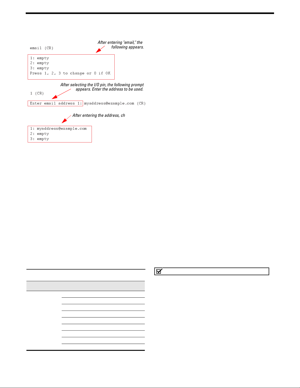
email (CR)
1: empty
2: empty
3: empty
Press 1, 2, 3 to change or 0 if OK
1 (CR)
2: empty
3: empty
After entering "email," the
following appears.
After selecting the I/O pin, the following prompt
appears. Enter the address to be used.
After entering the address, changes are
reflected. To add another address, enter
the word "email" again.