TeleEye DT-103G User manual

Tele
Eye DT Series
Dialup CCTV Transmitter
DT-103G
DT-103P
DT-103D
Installation Guide

Notice:
Signal Communications Limited reserves the right to make improvements to the
product described in this manual at any time and without notice.
This manual is copyrighted. All rights are reserved. This manual may not be copied,
reproduced or translated in whole or part without prior consent from Signal
Communications Limited.
Tele
Eye is a trademark of Signal Communications Limited and is registered in China,
Hong Kong, US and other countries.
All other trademarks are the property of their respective owners.
Copyright (c) 2004 Signal Communications Limited (A member of
Tele
Eye
Group). All rights reserved.
Version 1.01
Limits of Liability and Disclaimer of Warranty
Signal Communications Limited has taken care in preparation of this manual, but
makes no expressed or implied warranty of any kind and assume no responsibility for
errors or omissions. No liability is assumed for incidental or consequential damages in
connection with or arising out of the use of the information or accessories contained
herein.
Features and specifications are subject to change without prior notice.

Table of Contents
SECTION 1
INTRODUCTION 1
•Features 2
SECTION 2
INSTALLATION OF
Tele
Eye Dialup CCTV
A. Removing the Package 3
B.PanelDescription 4
GSM version : DT-103G 4
PSTN version : DT-103P 5
ISDN version : DT-103D 6
C. Connecting to
Tele
Eye Dialup CCTV 8
GSM version : DT-103G 8
PSTN version : DT-103P 10
ISDN version : DT-103D 11
D. Audio Connection of
Tele
Eye Dialup CCTV 13
E. Aux Port Connection of
Tele
Eye Dialup CCTV 14
F.
Tele
Eye Dialup CCTV Configuration 16
G. Remote Monitoring with
Tele
Eye Dialup CCTV 17
APPENDIX A
Q & A 18
APPENDIX B
PHONE JACK PIN ASSIGNMENT 20
SECTION C
DT-103G LED STATUS 21
SECTION D
SPECIFICATIONS 22

Tele
Eye Dialup CCTV Installation Guide Page 1
Introduction
1
INTRODUCTION
Tele
Eye Dialup CCTV is a series of all-in-one remote video and audio
transmitters to allow you looking after your remote premises via PSTN, ISDN or
GSM network.
With built-in modem and audio design,
Tele
Eye Dialup CCTV is extremely easy
to install. By simply hooking up video cameras, microphone and telephone line to
the
Tele
Eye Dialup CCTV transmitter, you can monitor your premises anytime
you want. Fast image update rate of up to 10fps at 33.6kbps can be achieved.
Tele
Eye Dialup CCTV is ideal for alarm verification. The system can handle and
verify alarm events by dialing back to the control center, recording video and
alerting security personnel automatically. The remote public addressing allows
broadcasting of warning message to deter illegal activity. When deploying the
system with
Tele
Eye Central Monitoring Station CMS01, you can manipulate
hundreds of remote sites effectively in one central location.
With
Tele
Eye Dialup CCTV, you just dial and see what’s happening there!
SECTION

Tele
Eye Dialup CCTV Installation Guide Page 2
Introduction
Features
zDifferent connection models – PSTN, ISDN & GSM
z4 video & alarm inputs
zBuilt-in modem design
zResolution up to 640x480 pixels
zRemote audio transmission (DT-103P and DT-103D only)
zAuto dial-up upon alarm event
zPre- & post-alarm video recording
zRemote telemetry control
zSelf diagnostic & recovery
zEasy installation & configuration

Tele
Eye Dialup CCTV Installation Guide Page 3
Installation of
Tele
Eye Dialup CCTV
2
INSTALLATION OF
Tele
Eye Dialup
CCTV
A
A.
.
R
Re
em
mo
ov
vi
in
ng
g
t
th
he
e
P
Pa
ac
ck
ka
ag
ge
e
After removing the package, make sure you have the following items:
1.
Tele
Eye Dialup CCTV transmitter
2. Software CD
3. AC to DC Power Adapter
4. 4-wire telephone cable (DT-103P and DT-103D only)
5. External antenna adapter cable (DT-103G only)
6. External antenna and SIM removal forceps (DT-103G only)
7. Warranty card
8. Serial number and registration code card
9. Installation Guide
SECTION
1 2 3 7 & 8 & 9
4 5 6

Tele
Eye Dialup CCTV Installation Guide Page 4
Installation of
Tele
Eye Dialup CCTV
B
B.
.
P
Pa
an
ne
el
l
D
De
es
sc
cr
ri
ip
pt
ti
io
on
ns
s
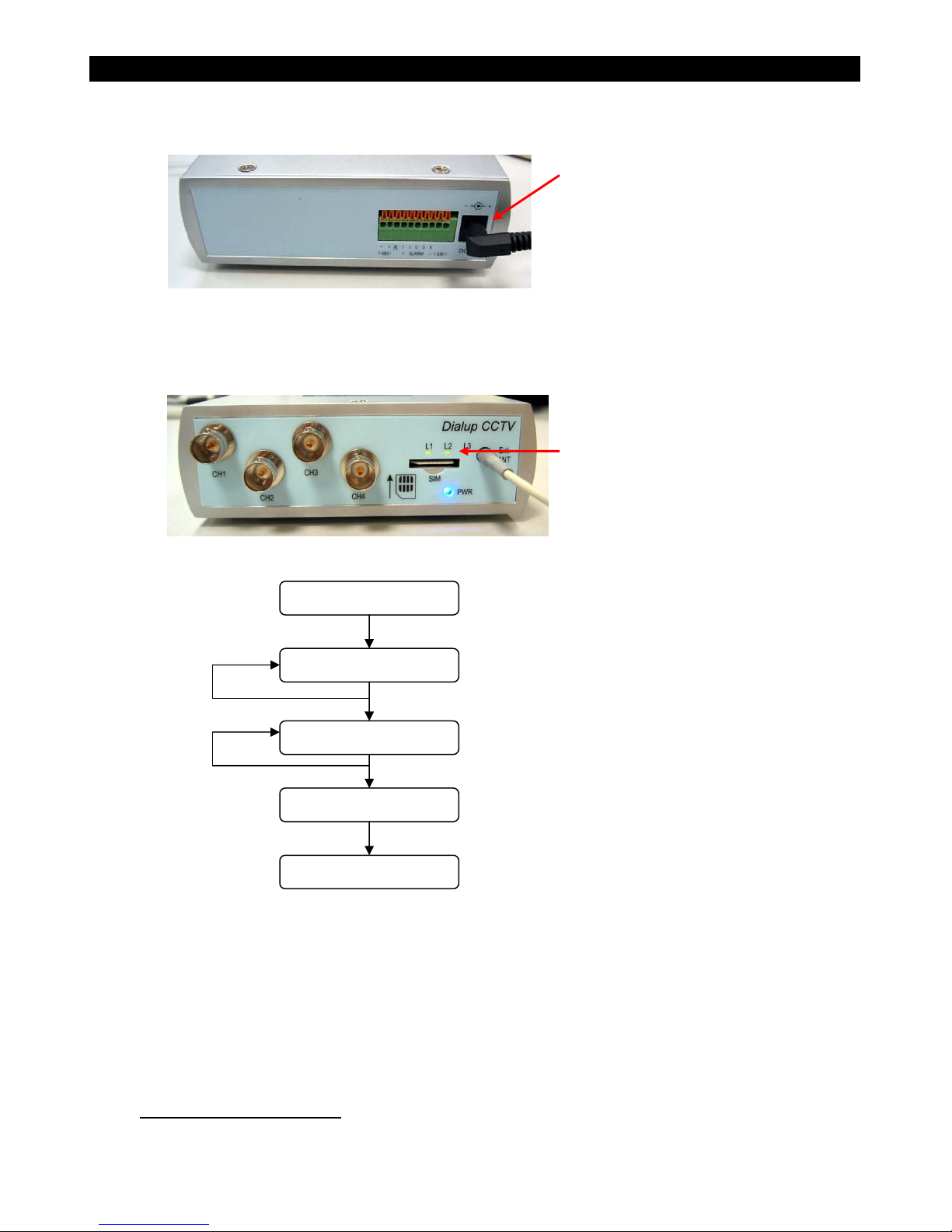
GSM Version : DT-103G
1. Video input connectors
-totally 4 input video channels (CH1-CH4)
-input video signal is 1Vp-p
2. SIM card slot
-Slot for inserting the SIM card with metal contacts upwards
3. Blue indication Light Emitting Diodes (LED)
-Power (PWR) LED turns on when power is up
4. Green/Red indication Light Emitting Diodes (LED)
-L1, L2, L3 LEDs dedicated for GSM status indication
5. External antenna connector
-FME female connector for connecting to external antenna
6. Aux port
-RS485 interface for Telemetry control
-4 alarm channels input for alarm notification
-1 pair of switch channel for control
6
7
1
2
3
4
5
Tele
Eye Dialup CCTV Installation Guide Page 5
Installation of
Tele
Eye Dialup CCTV
7. Power supply
-DC jack for 12V DC, 1A power input
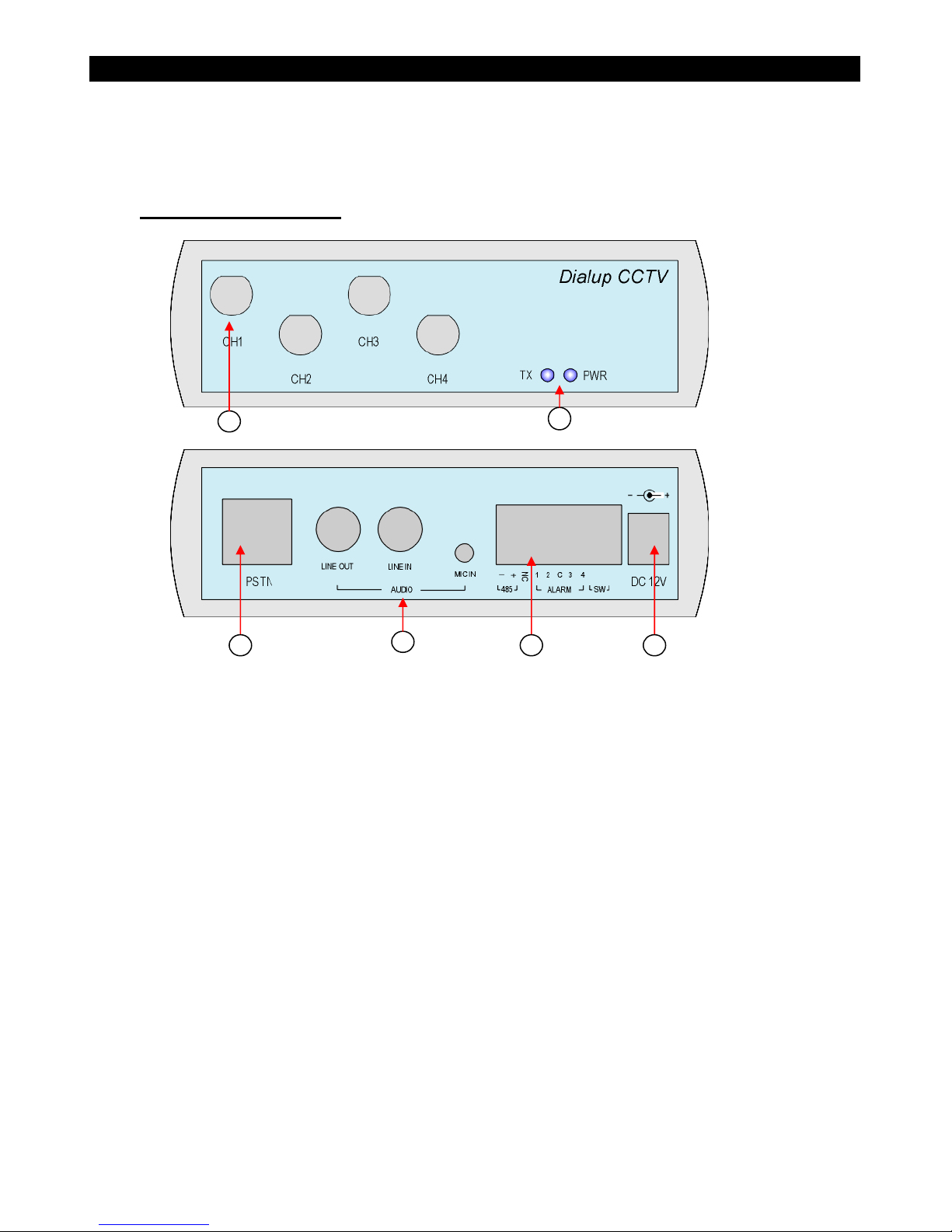
PSTN Version : DT-103P
1. Video input connectors
-totally 4 input video channels (CH1-CH4)
-input video signal is 1Vp-p
2. Indication Light Emitting Diodes (LED)
-Power (PWR) LED turns on when power is up
-Transmit (TX) LED turns on when data is transmitted
3. PSTN phone jack
-RJ45 phone jack for connecting
Tele
Eye Dialup CCTV to PSTN network.
See Appendix B for details.
4. Audio connectors
-Line in audio source for transmitting audio to
Tele
Eye III+ Reception
Software
-Line out audio output for speaker
-Mic in audio source for transmitting microphone audio to
Tele
Eye III+
Reception Software
1
2
3
4
5
6

Tele
Eye Dialup CCTV Installation Guide Page 6
Installation of
Tele
Eye Dialup CCTV
5. Aux port
-RS485 interface for Telemetry control
-4 alarm channels input for alarm notification
-1 pair of switch channel for control
6. Power supply
-DC jack for 12V DC, 1A power input
ISDN Version : DT-103D
1. Video input connectors
-totally 4 input video channels (CH1-CH4)
-input video signal is 1Vp-p
2. Indication Light Emitting Diodes (LED)
-Power (PWR) LED turns on when power is up
-Transmit (TX) LED turns on when data is transmitted
3. ISDN phone jack
-RJ45 phone jack for connecting
Tele
Eye Dialup CCTV to ISDN network.
See Appendix B for details.
4. Audio connectors
-Line in audio source for transmitting audio to
Tele
Eye III+ Reception
Software
1
2
3
4
5
6

Tele
Eye Dialup CCTV Installation Guide Page 7
Installation of
Tele
Eye Dialup CCTV
-Line out audio output for speaker
-Mic in audio source for transmitting microphone audio to
Tele
Eye III+
Reception Software
5. Aux port
-RS485 interface for Telemetry control
-4 alarm channels input for alarm notification
-1 pair of switch channel for control
6. Power supply
-DC jack for 12V DC, 1A power input

Tele
Eye Dialup CCTV Installation Guide Page 8
Installation of
Tele
Eye Dialup CCTV
C
C.
.
C
Co
on
nn
ne
ec
ct
ti
in
ng
g
t
to
o
T
Te
el
le
e
E
Ey
ye
e
D
Di
ia
al
lu
up
p
C
CC
CT
TV
V
To perform remote monitoring, you must connect the
Tele
Eye Dialup CCTV to the
network first. For different models of
Tele
Eye Dialup CCTV, you need to connect
them to different networks accordingly.
GSM Version : DT-103G
Tele
Eye Dialup CCTV GSM version, DT-103G is used to transmit video over the
Global System for Mobile communication (GSM) network. For transmitting data over the
GSM network, a GSM modem is required for making connection and data transmission.
DT-103G have a built-in GSM modem so that you just need to insert a SIM card and an
external antenna to setup the transmitter. The built-in GSM modem support High Speed
Circuit Switch Data (HSCSD) of slot 2+2, which is capable of transmitting data at a rate
of 28.8kbps. The built-in GSM modem support dual band of 900MHz and 1800MHz.
What you need:
-DT-103G transmitter
-SIM card with incoming data service enabled (or mobile data service), see
Appendix A on how to check your SIM support incoming data service or not
-External antenna
-Antenna adapter cable
-Power adapter
Procedures:
1. Insert the SIM card with incoming data service enabled to the SIM slot on DT-103G.
2. Connect the external antenna to DT-103G with the antenna adapter cable. The SMB
connector is used to plug in to the Ext. ANT hole on DT-103G.
Insert the SIM to the SIM card slot
with metal contacts upwards. The
SIM card must enable the “incoming
data service”
Connect DT-103G with external
antenna with the antenna adapter cable
FME connectorSMB connector
Tele
Eye Dialup CCTV Installation Guide Page 9
Installation of
Tele
Eye Dialup CCTV
3. Power on DT-103G by insert the power jack.
4. After power up, the blue PWR LED will blink 6 times and then remains on indicates
system boot up. The PWR LED and the status LED L1, L2, L3 will be on/off
according to the state of DT-103G.
5. Now the DT-103G is ready for dialing. See section G for access the
Tele
Eye
Dialup CCTV from PC for video monitoring.
PSTN Version : DT-103P
Plug in the power adapter jack with
12VDC supply
During power up, L1, L2 and L3 will
b
link/scan according to the operation
mode. Please see appendix C for
GSM status LED indication
PWR: blue
L1, L2, L3 : red/green blinking when no SIM
Check Signal Level
Check SIM card
Scanning Network
Standby
No network
No SIM /
SIM error
PWR: blue blink 6 times
L1, L2, L3 : orange
PWR: blue
L1, L2, L3 : green scanning
PWR: blue
L1, L2, L3 : depends on signal strength
PWR: blinking depends on signal strength
L1, L2 : off L3: green
System Power up

Tele
Eye Dialup CCTV Installation Guide Page 10
Installation of
Tele
Eye Dialup CCTV
Tele
Eye Dialup CCTV PSTN version, DT-103P is used to transmit video and audio
over the Public Switch Telephone Network (PSTN), or simply analog telephone network.
For transmitting data over the PSTN network, modem is required which is used to
modulate the digital signals for transmitting over the telephone line, and then demodulate
the signal to extract the raw digital data back.
DT-103P have a built-in V.90/V.92 analog modem so that you just need to use a 4-wire
telephone line to connect DT-103P to the PSTN network directly.
What you need:
-DT-103P transmitter
-4-wire telephone wire
-Power adapter
Procedures:
1. Connect the RJ-45 side of the 4-wire telephone cable to DT-103P.
2. Connect RJ-11 side of the 4-wire telephone cable to telephone socket from the
telephone company.
3. Power on DT-103P by insert the power jack.
Plug in the power adapter
jack with 12VDC supply
Plug the 4-wire RJ45 jack
to the DT-103P PSTN
socket
PSTN Socket
Plug the 4-wire RJ42 jack to
the wall PSTN socke
t

Tele
Eye Dialup CCTV Installation Guide Page 11
Installation of
Tele
Eye Dialup CCTV
4. After power up, the blue PWR LED will blink 6 times and then remains on indicates
system boot up.
5. Now the DT-103P is ready for dialing. See section G for access the
Tele
Eye
Dialup CCTV for video monitoring.
ISDN Version : DT-103D
Tele
Eye Dialup CCTV ISDN version, DT-103D is used to transmit video and audio
over the Integrated Service Digital Network (ISDN). For transmitting data over the ISDN
network, an ISDN TA (or ISDN modem) is required for setting up the connection.
DT-103D have a built-in ISDN TA so that you just need to use a 4-wire telephone line to
connect DT-103D to the ISDN network directly. The built-in ISDN TA support 1B+D
channels which is capable of transmitting data at a rate of 64kbps. The line interface for
the built-in ISDN TA is S/T interface, and the default B-channel protocol is V.120.
What you need:
-DT-103D transmitter
-4-wire telephone wire
-Power adapter
Procedures:
1. Connect the RJ-45 side of the 4-wire telephone cable to DT-103D.
2. Connect RJ-11 side of the 4-wire telephone cable to telephone socket from the
telephone company.
3. Power on DT-103D by insert the power jack.
PWR LED blinks 6 times and then
remains on. Now the DT-103P is
ready for dialing in

Tele
Eye Dialup CCTV Installation Guide Page 12
Installation of
Tele
Eye Dialup CCTV
4. After power up, the blue PWR LED will blink 6 times and then remains on indicates
system boot up.
5. Now the DT-103D is ready for dialing. See section G for access the
Tele
Eye
Dialup CCTV from PC for video monitoring.
PWR LED blinks 6 times and then
remains on. Now the DT-103D is
ready for dialing in
Plug in the power adapter
jack with 12VDC supply
Plug the 4-wire RJ45 jack
to the DT-103D ISDN
socke
t
ISDN Socket
Plug the 4-wire RJ-11jack to
the wall ISDN socket, S/T
interface
Tele
Eye Dialup CCTV Installation Guide Page 13
Installation of
Tele
Eye Dialup CCTV
D
D.
.
A
Au
ud
di
io
o
C
Co
on
nn
ne
ec
ct
ti
io
on
n
o
of
f
T
Te
el
le
e
E
Ey
ye
e
D
Di
ia
al
lu
up
p
C
CC
CT
TV
V
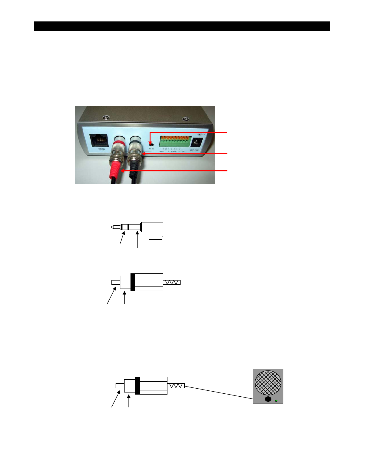
DT-103P and DT-103P support built-in audio functions. You can use the transmitter for
remote audio monitoring or for public addressing purpose. The audio part includes 1 line
in connector, 1 line out connector and 1 microphone in connector. The orientation of
these connectors is shown in the following diagram.
For remote audio monitoring, you should use either the microphone input or the line
input as the audio source. The signal assignments for the connectors are show below.
For public addressing, you should use the Aux out RCA connector to connect the audio
output to a amplifier or a speaker with amplifier. The signal pin assignments are shown in
the following diagram. Please read section 9 “Audio Control” of user manual of
Tele
Eye III+ WRS3-AD for audio monitoring and public addressing.
Microphone input
Line input from audio source
Line output to amplifier/speaker
GND
Mic. signal
Audio signal
input (line level) GND
Microphone connector signal
assignment
Aux in (RCA) signal assignment
Audio signal
output (line level) GND Amplifier or speaker
with amplifier

Tele
Eye Dialup CCTV Installation Guide Page 14
Installation of
Tele
Eye Dialup CCTV
E
E.
.
A
Au
ux
x
P
Po
or
rt
t
C
Co
on
nn
ne
ec
ct
ti
io
on
n
o
of
f
T
Te
el
le
e
E
Ey
ye
e
D
Di
ia
al
lu
up
p
C
CC
CT
TV
V
All models of DT series have an aux port attached with it. The aux port contains one
RS485 interface, four alarm inputs and one pair of switch output. The pin assignment of
the aux port is show below.
Pin no. from
left to right Definition Remark
1 RS485- RS485 interface negative terminal
2 RS485+ RS485 interface positive terminal
3 NC Not Connected
4 Alarm 1 Alarm 1 input
5 Alarm 2 Alarm 2 input
6 C Common for all alarm inputs
7 Alarm 3 Alarm 3 input
8 Alarm 4 Alarm 4 input
9 SW_A Switch output terminal
10 SW_B Switch output terminal
Before setup the required aux port, you need to prepare copper wires. In order to insert
the copper wires firmly into
Tele
Eye Dialup CCTV, the end of copper wire should
be cut according to following specifications:
The aux port of
Tele
Eye Dialup
CCTV is a 10 pin terminal block
6mm 6mm
Copper wire end inserted into
DT aux port
DT aux port

Tele
Eye Dialup CCTV Installation Guide Page 15
Installation of
Tele
Eye Dialup CCTV
E1. Connecting for telemetry control
Connect the RS485+/RS485- terminal of
Tele
Eye Dialup CCTV to the
RS485+/RS485- terminal of the speed dome respectively. Category 5 STP or UTP cable
is one of the choices for the RS485 cables.
E2. Connecting for alarm sensor input
Tele
Eye Dialup CCTV supports 4 alarms, or 3 alarms with 1 arm/disarm input. You
can directly connect the alarm sensors to the alarm port as illustrated in the following
diagram.
E3. Connecting for switch control
The switch output of
Tele
Eye Dialup CCTV can be used to control on/off of some
electrical device. However, the maximum rating for the switch output is 24VAC, 1A only.
If you want to use the switch to control device with large ratings, you can use the cascade
configuration. An example configuration is shown below.
Tele
Eye Dialup
CCTV Alarm port
Alarm 1
Alarm 2
Alarm 3
Alarm 4
Common
Sensor 1
Sensor 2
Sensor 3
Sensor 4
485-
Tele
Eye Dialup CCTV
RS485
p
or
t
485 +
24Vac
220Vac
24Vac Relay
Fluorescent Lamp

Tele
Eye Dialup CCTV Installation Guide Page 16
Installation of
Tele
Eye Dialup CCTV
F
F.
.
C
Co
on
nf
fi
ig
gu
ur
ra
at
ti
io
on
n
o
of
f
T
Te
el
le
e
E
Ey
ye
e
D
Di
ia
al
lu
up
p
C
CC
CT
TV
V
Before access the
Tele
Eye Dialup CCTV, you need to do the configurations include
video mode and registration checking settings. Follow the steps below:
1. Open the transmitter configure software by click [Start]->[
Tele
Eye III+]-
>[
Transmitter configuration
]. The transmitter configuration software should
have version 1.1M or higher.
2. Select the device driver, which is the driver for the modem being connected to your
PC for connecting to
Tele
Eye Dialup CCTV.
3. Enter the phone number and key in the administration password of the
Tele
Eye
Dialup CCTV you want to configure.
4. Click connect to read the current status of the
Tele
Eye Dialup CCTV.
5. Select [Enable] if you want to enable the registration checking for enhanced security
level of accessing
Tele
Eye Dialup CCTV.
6. Select [Speed] for speed mode of video performance and [Quality] for quality mode
of video performance.
7. Click [Save and Exit] button to save your setting in
Tele
Eye Dialup CCTV. The
Tele
Eye Dialup CCTV will reset and the settings will take effect immediately.
Tele
Eye Dialup CCTV Installation Guide Page 17
Installation of
Tele
Eye Dialup CCTV
G
G.
.
R
Re
em
mo
ot
te
e
m
mo
on
ni
it
to
or
ri
in
ng
g
w
wi
it
th
h
T
Te
el
le
e
E
Ey
ye
e
D
Di
ia
al
lu
up
p
C
CC
CT
TV
V
After installing
Tele
Eye Dialup CCTV and connect the cameras to the video inputs,
you can start remote monitoring by using
Tele
Eye III+ WRS3-AD Reception Software,
the steps are listed below:
1. Install
Tele
Eye III+ WRS3-AD software in your computer.
2. Click [Start]->[
Tele
Eye III+]->[
Tele
Eye III+ WRS3-AD] to start the program.
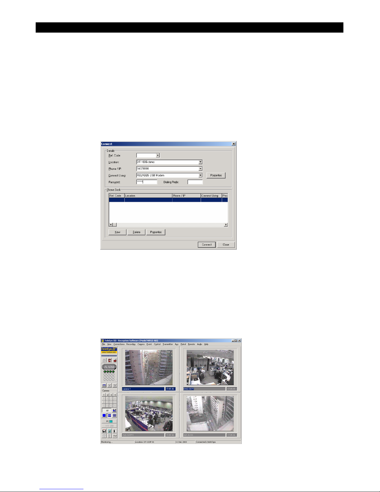
3. Click [Connections]->[Connect] from the main menu to pop up the connect dialog.
4. Enter the Location, Phone number for the
Tele
Eye Dialup CCTV, select the
modem driver for the modem attached with your PC, and enter the password. Default
password for all
Tele
Eye Dialup CCTV is “000000”.
5. Click [Connect] button to make connection.
6. Connection will be established within few seconds, and you will see the videos on the
screen. You can access the video by change the quality, brightness, etc. Please read
section 3 “Making Connection” of user manual of
Tele
Eye III+ WRS3-AD for
detail.
This manual suits for next models
2
Table of contents
Other TeleEye Transmitter manuals


