EBS WX2NB Assembly instructions

WX2NB Manual v.1.0 Page 1 / 40
TRANSMITTER
WX2NB
Installation and
programming manual
Version of the manual: v1.0
Date of issue: 2019.03.18
Firmware version: 2.5.2
GPRS transmitter configurator version: 1.4.91.4

WX2NB Manual v.1.0 Page 2 / 40
DECLARATION OF COMPLIANCE
We, EBS Sp. z o.o., declare with full responsibility that the present
product meets all requirements provided for in the Directive
1999/5/EC of European Parliament and Council dated 9 March 1999
The copy of the “Declaration of Compliance” can be found at
www.ebssmart.com in the "Technical data and certificates" section.
IMPORTANT INFORMATION
Crossed symbol of a trash bin means that at the territory of European
Union, the product, after finishing its useful life, shall be disposed of
in a separate, specially dedicated collection point. It refers to the
equipment itself and its accessories marked with that symbol. The
products shall not be disposed of together with non-sortable
municipal waste.
The content of the document is presented “as is”. The present
document shall not be deemed to be providing any warranties, either express or
implicit, including but not limited to, any implied warranties of merchantability or
fitness for a particular purpose, unless it is required by relevant law. The
manufacturer reserves the right to amend the present document or withdraw it any
time, without notice.
The manufacturer of the equipment promotes the sustainable development policy. It
reserves the right to modify and improve any functions of the product described in
the present document without previous notice.
The availability of particular functionalities will depend on the software version of
the equipment. Details can be found at the nearest dealer of the equipment.
In no event, the Manufacturer shall be held liable for any loss of data or loss of
profits or any specific, incidental, consequential or indirect damages caused in any
way.
MANUFACTURER
EBS Sp. z o. o.
59 Bronislawa Czecha St.
04-555 Warsaw, POLAND
Webpage : www.ebssmart.com

WX2NB Manual v.1.0 Page 3 / 40
TABLE OF CONTENTS
1. INTRODUCTION............................................................................................... 5
2. FUNCTIONAL AND TECHNICAL PARAMETERS ....................................................... 6
3. ASSEMBLY AND WIRING................................................................................... 7
3.1. WX2NB TRANSMITTER .............................................................................. 7
3.2. INPUT CONFIGURATION ............................................................................ 8
3.3. LX-ZAS POWER SUPPLY............................................................................. 9
4. OPERATION .................................................................................................. 10
5. CONFIGURATION PROGRAM ............................................................................ 11
5.1. INITIAL REMARKS .................................................................................. 11
5.2. COMPUTER –REQUIREMENTS .................................................................. 11
5.3. PROGRAM FUNCTIONS ............................................................................ 11
5.3.1. File->New ....................................................................................... 12
5.3.2. File->Open...................................................................................... 12
5.3.3. File->Save ...................................................................................... 12
5.3.4. File->Language ............................................................................... 12
5.3.5. File->Connections ............................................................................ 12
5.3.6. File->Automatic device settings backup .............................................. 14
5.3.7. File->Exit........................................................................................ 14
5.3.8. Operations->Read ........................................................................... 14
5.3.9. Operations->Send ........................................................................... 15
5.3.10. Operations->Restore default settings ................................................. 15
5.3.11. Operations->System events history ................................................... 16
5.3.12. Operations->Device monitor ............................................................. 16
5.3.13. Help->About program ...................................................................... 16
6. PROGRAMMABLE PARAMETERS........................................................................ 17
6.1. ACCESS................................................................................................. 17
6.1.1. Device mode ................................................................................... 18
6.1.2. Wi-Fi settings .................................................................................. 18
6.1.3. Network parameters......................................................................... 18
6.1.4. Data Transmission ........................................................................... 18
6.2. TRANSMISSION...................................................................................... 20
6.3. INPUTS/OUTPUTS ................................................................................... 21
6.3.1. Inputs configuration ......................................................................... 21
6.3.2. Partitions ........................................................................................ 24
6.3.3. Output configuration ........................................................................ 25
6.3.4. Advanced outputs control.................................................................. 26
6.4. MONITORING ......................................................................................... 28
6.4.1. Wi-Fi On / Wi-Fi Off.......................................................................... 28
6.4.2. Skip initial state............................................................................... 28
6.4.3. Power loss ...................................................................................... 29
6.4.4. Low DC power voltage ...................................................................... 29
6.5. LINK CONTROL....................................................................................... 29
6.5.1. Wi-Fi .............................................................................................. 29
6.6. PHONE LINE........................................................................................... 30
6.6.1. Phone line....................................................................................... 30
6.6.2. First and Second phone number ........................................................ 31
6.7. FIRMWARE ............................................................................................ 32
6.8. DEVICE MONITOR................................................................................... 34
6.9. EVENTS HISTORY ................................................................................... 34
7. DEVICE PROGRAMMING.................................................................................. 35
7.1. LOCAL PROGRAMING .............................................................................. 35
7.2. REMOTE PROGRAMMING ......................................................................... 35
7.2.1. The first programming of device ........................................................ 35
7.2.2. Reprogramming of device ................................................................. 36
8. RECEIVING OF MESSAGE................................................................................ 37
8.1. LX PROTOCOL ........................................................................................ 37
9. LED DIODES INDICATION ............................................................................... 38
WX2NB Manual v.1.0 Page 4 / 40
9.1. LOGGING TO Wi-Fi NETWORK .................................................................. 38
9.2. Wi-Fi RANGE .......................................................................................... 38
9.3. DATA TRANSMISSION ............................................................................. 38
9.4. PROGRAMMING ...................................................................................... 38
9.5. FIRMWARE UPDATING............................................................................. 39
9.6. SYSTEM ERROR ...................................................................................... 39
10. REVISION HISTORY .................................................................................... 40

WX2NB Manual v.1.0 Page 5 / 40
1. INTRODUCTION
Transmitter WX2NBis an advanced microprocessor device, made with surface
moulding technology and designed according to the latest trends. It is intended for
data package transmission from electronic building security systems or from other
technical devices through a wireless connection to a local area network (WLAN).
Due to many settings a transmitter may be applied with many systems of various
requirements. The device is basically purposed for data transmission from security
systems installed in detached houses and in small business facilities. It also have
input for connection of an alarm control panel’s phone communicator. This provides
for a cheap system of data transmission.
Communication with a monitoring station follows by Wi-Fi technology.
An advanced encoding methods like a 256 bytes encoding key and AES (Advanced
Encryption Standard) provides for security of data transmission. As a result
reception of this transmission is possible with OSM.Server monitoring receiver
system.
Programming of receiver is possible:
oLocally on computer and with recommended “GPRS transmitter
configurator” software
oRemotely - via Wi-Fi network

WX2NB Manual v.1.0 Page 6 / 40
2. FUNCTIONAL AND TECHNICAL PARAMETERS
Inputs:
(programmable)
4 signal inputs (NO, NC, EOL-NO, EOL-NC, DEOL-NO,
DEOL-NC),
1 DTMF
Outputs:
(programmable)
1
Operation modes:
Wi-Fi transmission
Serverless
Configuration:
Remote –via Wi-Fi network
Locally –from PC with the use of software and GD-PROG
cable with RS-232 link
Security:
Wi-Fi transmission –AES encoding
Loading of OUT1 output
50 mA
Working temperature
-10ºC ~ +55 ºC
Operating humidity
5% - 93%
In dependence from user's decision transmitter can be delivered in different
versions. Therefore also the parameters as type of the power supply voltage,
current consumption as well as the dimensions were introduced for following options
separately:
Option 1 –Transmitter WX2NB + power supply LX-ZAS in metal/plastic box
Option 2 –PCB of transmitter WX2NB
Option 1
Option 2
Voltage
typ. 230 V AC
(190 –250 V AC)
50 –60 Hz
typ. 12 V DC
(12 –14 V DC)
Current consumption
(average/max)
90 mA / 350 mA
73 mA / 345 mA
Power consumption
(average/max)
3 W / 10 W
(recommended transforer 20W)
Dimensions
255 x 255 x 90 mm
(metal/plastic box)
102 x 73 x 35 mm

WX2NB Manual v.1.0 Page 7 / 40
3. ASSEMBLY AND WIRING
Transmitter is delivered along with a power supply (See below). The manufacturer
provides necessary wiring linking a power supply with the transmitter, and
described procedures relate to wiring of a transmitter printed circuit board.
Switch power off to perform any connection.
3.1. WX2NB TRANSMITTER
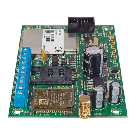
Figure 1. WX2NB Transmitter with LX-ZAS
a) Connections of wires shall be made with due care to prevent any faults or dead
shorts. Places of connections shall be protected against weather conditions.
a) According to the above figure terminals of transmitter shall be connected to:
Terminal
Connection description
T1 –R1
Connection to alarm control panel phone communicator
GND
Device ground, common for other input and output

WX2NB Manual v.1.0 Page 8 / 40
IN1 - IN4
Signal inputs. Possible connection of detectors contacts or
alarm control panel outputs. GND terminal is common for
all inputs.
OUT1
Type OC output.. It may control external device. Provides
ground during activation.
V+
Connect to the positive pole (+13,8V) of the EBS power
supply.
GND
Connect to the negative pole of the power supply.
After careful connections examination a battery may be connected (to +/- AKU
terminals of LX-ZAS power supply) and then power may be switched on for
transformer and programming procedure of transmitter may begin (see Chapter 6).
Manufacturer reserves the right to amend appearance of printed circuit
with no effect on functionality of device.
3.2. INPUT CONFIGURATION
Inputs IN1 - IN4 might work as normally closed (NC) or normally open (NO).
Additionally inputs might be configured as end of line (EOL-NO or EOL-NC) with
resistors 2,2kΩ or as double end of line (DEOL-NO or DEOL-NC) with resistor 1,1kΩ.
Figure 4. Configuration of input lines

WX2NB Manual v.1.0 Page 9 / 40
3.3. LX-ZAS POWER SUPPLY
The dedicated power supply LX-ZAS (product of EBS) possesses the following
parameters:
Parameter
Value
Served batteries
Acid-leaded 12V
Maximum voltage of charging battery
13.8V
Charging current
0.2A or 1A (switched by jumper)
Voltage of signaling of low level
11 V
Voltage of switch-off battery
9.5V
as well as it characterizes with following proprieties:
protection against opposite connecting battery.
protection against excessive unloading battery:
The battery protects before damage in case of long-lasting fading the AC. In
case of lack the AC and unloading below voltage 9.5 V the battery becomes
separated from device automatically.
quick charging of the battery:
The jumper showed on drawing place causes settlement of maximum
current of charging on 1A. We recommended jumper be taken off and the
current of charging battery carries out 0.2 A.
Figure 5. Choice of current of charging the battery
Note: the applying the quick charging can bring to damage of battery.
Jumper ON => charging current 1A
Jumper OFF => charging current 0,2A

WX2NB Manual v.1.0 Page 10 / 40
4. OPERATION
The device communicates with a monitoring station using Wi-Fi, so the
transmitter can only be used in areas where wireless local area network is available.
If status of inputs is the same as programmed one (NO, NC, EOL-NO, EOL-
NC, DEOL-NO, DEOL-NC) a device stays in a rest. Change of status on any input
results in immediate signal transmitting of this event by the device.
Note :
Each input (IN1 –IN4) may be individually defined as normally open (NO) or
normally closed (NC). It means that when input was defined as NO, input shorting
will be an active state and when input was defined as NC, input opening will be an
active state. EOL and DEOL (parametrized and double parametrized) are options
where you use 1 or 2 resistors to distinguish alarm from sabotage.
All inputs react solely to status changes, which means that transmission will
only be performed if an active status appears at an input and remains for a pre-set
minimum time. If an active status is sustained for longer than the minimum time, it
only causes a single signal. Inputs can be activated again (another transmission)
after they return to their basic status.
To configure the transmitter to work with an emergency exchange telephone
communicator, the telephone number that the communicator reacts to must be
entered in the transmitter's memory.
When the receiver of the emergency exchange telephone communicator
module is picked up, the exchange begins dialling the number it needs to connect
to. Once the exchange dials the telephone number, the transmitter generates a
confirmation signal and waits for data from the emergency exchange - subsequent
DTMF tones generated by the exchange are treated as data. Once a sufficient
number of DTMF symbols is sent (16 for ContactID), the transmitter generates a
KissOff signal. Data reception from the exchange is finished when the emergency
exchange telephone communicator module puts down the receiver.
If the telephone number dialled by the exchange is not identical to the
number to which the module reacts, it takes no action and waits for the exchange to
put down the receiver and pick it up again - starting with the receiver is picked up,
the number dialled by the telephone module of the exchange begins to be checked.
All programmable parameters are saved in non-volatile memory, so they are
not lost on loss of power. Restoring power causes automatic transmitter activation
with the previously saved settings.

WX2NB Manual v.1.0 Page 11 / 40
5. CONFIGURATION PROGRAM
5.1. INITIAL REMARKS
GPRS transmitters configurator may be downloaded at www.ebs.pl (login: ebs,
password: ebs)
To install program an installation wizard shall be started that performs installation
in default place C:\Program Files\EBS\. During installation process shortcuts on
screen and Windows menu may be created.
5.2. COMPUTER –REQUIREMENTS
Minimum requirements for computer system where configuration software is to be
installed are the following:
Hardware:
Processor 1GHz or faster,
1 GB RAM,
4GB HDD,
Software:
Operating system: Windows 7 or newer,
.NET Framework 4,5 software
5.3. PROGRAM FUNCTIONS
After installation and program starting a main view shall be displayed on screen.
Thanks to this view an access to program or programmable parameters of device is
possible (See chapter 6).
Main window of program is divided into some fields.
Main menu: at upper part of window, contains control and configuration options.
Main menu contents:
Main menu is available as icons on fast access bar:

WX2NB Manual v.1.0 Page 12 / 40
5.3.1. File->New
Opens new set of parameters. Editing of configuration parameters is possible.
Select type of device (WX2NB).
5.3.2. File->Open
If file contains saved settings, they may be used to program next device. Firstly a
catalogue where file has been saved shall be chosen and then name of file shall be
provided. Obtained data collection may be modified by the user. Any amendments
are effective if send to device.
5.3.3. File->Save
During programming many devices in different configurations, it is not necessary to
have in mind each one as it may be saved on hard disc or floppy disk under any
name and it may be loaded later on. This function save on disc any information from
configuration wizard window. After activation of function a dialog window appears
with request to provide file name. Default data is saved with CMI extension
(Configuration Memory Image).
5.3.4. File->Language
Allows for selection of any available languages (determined in attached exterior
language files).
5.3.5. File->Connections
Before programming of devices, a connection type shall be defined. It is possible to
do it with two methods:
- locally
- remotely.
5.3.5.1. Local connection
Local connection means that configuration software (namely computer on which is
installed) is directly connected to proper terminal of transmitter via special wire and
through RS-232 serial port (GD-PROG) or USB port or Bluetooth (MINI-PROG-BT,

WX2NB Manual v.1.0 Page 13 / 40
SP-PROG-BT). All channel connection (also USB and Bluetooth) "open" virtual COM
serial ports used in communication control panel-Configurator.
To program device or make any other operations (e.g. reading of device settings,
firmware amendments, etc.) it is necessary firstly to define connection parameters.
For the above purpose you shall use the following window, available after activating
File option from the Main Menu and selecting Connection function or after clicking
icon on a taskbar and opening RS232 tab.
Define:
Name of connection e.g. Local
Choose serial port e.g. COM1
Click on [Add] button to confirm settings. Connections shall be saved (and inserted
in table). From this time on program shall enable wires connection with device and
reading, and saving of parameters in WX memory will be possible.
In the next tab "MINI-PROG" (the name derived from the programmer) you have to
also define the connection parameters.
Operations are the same as with the "RS232" tab. Specify the name, the correct
COM port and add a connection.
Programmers MINI-PROG-BT and SP-PROG-BT have microUSB ports, through which
we can connect to the computer using the USB port, but also have built-in Bluetooth
interface.

WX2NB Manual v.1.0 Page 14 / 40
5.3.5.2. Remote connection
As mentioned above, the device and its software can be configured fully through Wi-
Fi. To perform programming in this mode, connection parameters must be defined
appropriately.
GPRS Tab
Configure OSM.Server connection parameters in this tab.
The following window will be displayed.
Define:
Connection name, e.g. Remote
Analyser name, e.g. Primary
Analyser address, e.g. www.ebs.pl
Port at which the analyser listens for commands, e.g. 9000
Confirm settings by clicking [Add]. The connection will be saved (and added
to the table). From now on, the software will enable connecting remotely to
the device and enable reading and saving parameters to WX memory.
5.3.6. File->Automatic device settings backup
All configuration settings including reread from devices and saved on devices are to
be automatically saved on hard disc. If during installation on configuring tool
settings have not been changed, files will be saved as follows:
C:\Program Files\ EBS\KonfiguratorLX\configs\WX2NB_20000
Catalog WX2NB_20000 contains all files in respect of WX2N with factory number of
20000 programming. The name contains date and time of operation and its type
(saving/ reading). Files have cmi extension.
5.3.7. File->Exit
Finishes program operation.
5.3.8. Operations->Read
Function reads data saved in memory. Exchange of data follows on port selected in
section “Select Connection Type” (See below description of option ”Configuration”).

WX2NB Manual v.1.0 Page 15 / 40
Correct reading is confirmed with message on a screen. Data downloaded from
device may be saved on file and use for other devices.
To use this function it is necessary to define type and parameters of connection.
E.g. for local connection the following view is displayed:
where:
Connection kind - serial port to which module is connected
Access code- service code of transmitter
5.3.9. Operations->Send
This function is analogical to the above one, at the same time it enables data saving
into EEPROM module. There is also possibility to set correct time into WX device.
Correct saving is confirmed with message on a screen.
5.3.10. Operations->Restore default settings
If operation “Read” finishes with error message (e.g. if access code is unknown) it is
possible to come back to default settings by selecting “Restore default settings”. e
“Do you want to overwrite current configuration with default values?”. After
confirming the following window shall appear:

WX2NB Manual v.1.0 Page 16 / 40
This operation is possible only with local connection. After operation completing
device parameters shall come back to default settings.
5.3.11. Operations->System events history
„Events history” provides information about last events stored in WX device
memory.
5.3.12. Operations->Device monitor
“Device Monitor” provides real-time information on WX device state.
5.3.13. Help->About program
Select this information to view additional information about program.

WX2NB Manual v.1.0 Page 17 / 40
6. PROGRAMMABLE PARAMETERS
Parameters available in configuration program are divided into groups: Access,
Transmission, Inputs/Outputs, Monitoring, Restrictions, SMS Notifications, Link
control, Phone line and Firmware. Every from these groups will be described in
detail in next part of this manual.
6.1. ACCESS
Service code
Protects the device against unauthorized access. It is used both when programming
the device and when operating it remotely (in Wi-Fi mode). By default it is set to
1111. It should be changed when the device is first activated (programmed). It
may contain up to seven alphanumeric characters.
Installation Specialist's code
Enables limited access to the device's programmable parameters. Changes to the
following tabs may not be made at this access level: Access, Link Control,
Telephone Line. Attempting to access windows with these parameters leads to an
insufficient rights message.
By default, the code is: 2222.

WX2NB Manual v.1.0 Page 18 / 40
6.1.1. Device mode
Depending on the user's preferences, the device can operate in 1 of 2 modes
(selected from a drop-down menu):
oWi-Fi: data transmission through wireless local area network.
oNo server: no transmissions with server.
6.1.2. Wi-Fi settings
SSID
ID name of the wireless network which the device is to be connected to.
Password
This password protects access to the wireless network.
6.1.2.1. WPS
WPS (Wi-Fi Protected Setup) is a feature that enables connecting WX2NB devices to
a wireless network with protections, without the need to enter the username and
password. This feature is strictly related to the network device (router) being
equipped with a WPS button, and with the button on the WX2NB Wi-Fi module (see
section 3.1WX2NB TRANSMITTER).
6.1.3. Network parameters
This section defines the IP address settings. By default it is set to DHCP (Dynamic
Host Configuration Protocol), but it can also be configured to static (when this
option is set, the fields below turn active).
DHCP is a protocol that dynamically assigns each computer with an IP address and
TCP/IP configuration parameters - default gate, subnet mask, DNS server
addresses.
With static IP, the Installation Specialist must enter the following fields him/herself:
Address:
IP address specific to the LAN which the device is to work with.
Mask
IP address mask, default: 255.255.255.0
Gate:
The computer's IP address in the LAN through which the device connects to the
communication server.
6.1.4. Data Transmission
6.1.4.1. Primary Server IP Address
The IP address of the monitoring system receiver (OSM.Server) or the computer on
which the "Communication Server" program is installed, e.g. 89.123.115.8. This
address may also be entered as the server's domain name. If so, at least one DNS
server address must be configured.

WX2NB Manual v.1.0 Page 19 / 40
6.1.4.2. Primary Server Port
Specifies the port set to receive data from the transmitter at the server.
6.1.4.3. Interval between consecutive attempts to connect to primary
server
A programmed device card will attempt to automatically connect to the server. This
setting defines the time interval (in seconds) after which the connection attempt will
be repeated, if the previous one was unsuccessful.
6.1.4.4. Number of connection attempts before switching to backup
server
Specify how many times the device will attempt to connect to the server. If it fails
the specified number of attempts, WX will begin the procedure to connect to the
backup server. This setting is active only if backup server parameters have been
specified.
6.1.4.5. Test event interval
At specific intervals, the device sends the "Test" signal, which informs the
monitoring station that the device is active. This field specifies the number of
seconds before this signal is sent again.
6.1.4.6. Always try to connect to primary server first
Checking this field means that the device will attempt to connect to the primary
server first, regardless of what backup server parameters are defined (in particular,
the number of connection attempts).
6.1.4.7. Backup Server IP Address
The IP address of the second (reserve) monitoring system receiver (OSM.Server) or
the computer on which the "Communication Server" program is installed, e.g.
89.130.125.82. This address may also be entered as the server's domain name. If
so, at least one DNS server address must be configured.
6.1.4.8. Backup Server Port
Specifies the port set to receive data from the transmitter at the server.
6.1.4.9. Interval between consecutive attempts to connect to backup
server
If the device is unable to connect to the primary server, then after reaching the pre-
defined number of attempts, it will begin the procedure to connect to the backup
server. This setting defines the time interval (in seconds) after which the connection
attempt will be repeated, if the previous one was unsuccessful.

WX2NB Manual v.1.0 Page 20 / 40
6.1.4.10. Number of connection attempts before switching to backup
server
Specify how many times the device will attempt to connect to the backup server. If
it fails the specified number of attempts, WX will revert to the procedure to connect
to the primary server.
6.1.4.11. Disconnect after time elapsed
Checking this field means that the device will disconnect from the backup server
once a specific time passes. Further actions depend on how the Connection Order
parameter is configured (see section 6.1.4.6). If this option is active, the device will
attempt to connect to the primary server. If this option is inactive, the device will
first complete its procedure to connect to the backup server, and if it fails, it will
attempt to connect to the primary server.
6.2. TRANSMISSION
For the purpose of maximum security of transmission, data is encrypted with AES
key. This option may be used for Wi-Fi transmission.
After selection of encrypted transmission you may use your own code (256 bytes –
signs 0-9 and A-F) or use default settings.
Table of contents
Other EBS Transmitter manuals

EBS
EBS LX2N Assembly instructions

EBS
EBS EPX400-5C Assembly instructions

EBS
EBS LX2NB Assembly instructions

EBS
EBS LX20G Assembly instructions

EBS
EBS LX1NB-5L Assembly instructions

EBS
EBS LX2NB Assembly instructions

EBS
EBS EPX400 Assembly instructions

EBS
EBS LX1NB-5L Assembly instructions

EBS
EBS PX200NB Assembly instructions

EBS
EBS LX20B Assembly instructions
Popular Transmitter manuals by other brands

E+E Elektronik
E+E Elektronik EE210 user guide

Crestron
Crestron DigitalMedia DM-TX-300N Operation guide

BEKA
BEKA BA474ND Installation & maintenance instructions

Fox
Fox Micron TXR Plus operating instructions

Critical Environment Technologies
Critical Environment Technologies CGAS-AP installation manual

API
API DuoPak APD 2037 instructions