TeleEye III+ VX Series User manual

VX Series
Video Recording Transmitter
VX-4001 / VX-4002
VX-8002 / VX-8004
VX-16004 / VX-16008
Installation Guide

Notice:
Signal Communications Limited reserves the right to make improvements to the product
described in this manual at any time and without notice.
This manual is copyrighted. All rights are reserved. This manual may not be copied, reproduced
or translated in whole or part without prior consent from Signal Communications Limited.
Tele
Eye is a trademark of Signal Communications Limited and is registered in China, Hong
Kong, US and other countries.
All other trademarks are the property of their respective owners.
Copyright (c) 2003 Signal Communications Limited (A member of
Tele
Eye Group).
All rights reserved.
Version 1.0
Limits of Liability and Disclaimer of Warranty
Signal Communications Limited has taken care in preparation of this manual, but makes no
expressed or implied warranty of any kind and assume no responsibility for errors or omissions.
No liability is assumed for incidental or consequential damages in connection with or arising out
of the use of the information or accessories contained herein.
Features and specifications are subject to change without prior notice.

Table of Contents
SECTION 1
INTRODUCTION 1
•Features 2
SECTION 2
INSTALLATION OF
Tele
Eye III+ VX FOR LOCAL MONITORING
•Removing the Package 3
•FrontPanelDescription 3
•RearPanelDescription 6
•Install
Tele
Eye III+ VX for Local Video Display 9
•Install
Tele
Eye III+ VX with Alarm Sensors and Relay Control Port 12
•Install
Tele
Eye III+ VX with Telemetry Control 14
SECTION 3
MENU OPERATION
• MenuStructure 15
• MainMenu 16
• Display Setup Menu 18
• Alarm Setup Menu 18
• Switch Setup Menu 19
• Recording Setup Menu 19
• TransmitterSetupMenu 20
• EventSetupMenu 20
• Arm/DisarmSetupMenu 21
• Password Setup Menu 21
SECTION 4
INSTALL
Tele
Eye III+ VX FOR REMOTE MONITORING
• Install
Tele
Eye III+ VX for Remote Monitoring with Network 22
A. Setup
Tele
Eye III+ VX for connection in LAN environment 22
B. Setup
Tele
Eye III+ VX for connection in WAN environment with static IP
25
C. Setup
Tele
Eye III+ VX for Broadband Internet connection with dynamic IP
using Internet router 26
D. Setup
Tele
Eye III+ VX for Broadband Internet connection with dynamic IP
using Broadband dialer 28
• Install
Tele
Eye III+ VX for Remote Monitoring with ISDN/PSTN Modem 31

SECTION 5
HARD DISK INSTALLATION AND FORMATTING
•Installation of Hard Disk 33
•HardDiskFormatting 35
•HardDiskScanning 36
•Recommended Hard Disk List 37
SECTION 6
USING BUILT-IN WEB SERVER
•EnabletheBuilt-InWebServer 38
•Connecting to the Web Server 39
APPENDIX A
sureLINK TECHNOLOGY
• How to Apply for sureLINK Address 41
APPENDIX B
IP ADDRESS SETUP FOR PC
• IP Address Setup for Window 98/ME 45
• IP Address Setup for Window NT/2000 48
• Router Configuration 49
SECTION C
SPECIFICATIONS 50

TeleEye III+ VX Installation Guide Page 1
Introduction
1
INTRODUCTION
The revolutionary TeleEye III+ VX Series Video Recording Transmitter (TeleEye
III+ VX) is an all-in-one video recording transmitter with dual composite video outputs
and removable hard disk for standalone and remote operations.
The TeleEye III+ VX supports triplex operation in which video monitoring, recording
and playback can be carried out simultaneously. Recording frame rate up to 100/120 fps
can be achieved. The highest recording resolution is 640x480 pixels. Recording
operation can be activated by manual, scheduled and event-driven modes.
The powerful TeleEye III+ VX works on broadband Internet economically and gives
you exceptionally well real time video transmission at speed up to 25/30 fps. Its
“sureLINK” technology allows low cost dynamic IP broadband Internet connection.
Powered by its proprietary video compression technology and remote accessibility,
TeleEye III+ VX provides simultaneous remote monitoring, recording and playback.
Users can keep track of live video and play back recorded video from any remote
locations.
TeleEye III+ VX is not only designed for connectivity but a total solution for video
monitoring and digital recording!
SECTION

TeleEye III+ VX Installation Guide Page 2
Introduction
Features
zVideo recording with rate up to 100/120 fps
zStandalone operations
zDual composite video outputs
zOSD menus
zFlexible connections – Internet, LAN, PSTN, ISDN, ADSL cable modem, mobile
network, etc.
zBuilt-in web server
zSupport static and dynamic IP
zReal time video transmission
Up to 30fps over LAN for NTSC
Up to 25fps over LAN for PAL
Up to 20fps on PSTN
zExcellent picture resolution up to 640 x 480 pixels
z4, 8, & 16 video & alarm inputs
zWeb-based video monitoring
zMobile video on Pocket PC
zTriplex Operation: Simultaneous video monitoring, recording & playback
zVideo motion detection
zEvent-driven recording
zProgrammable video recording
zAuto alarm dial-back
zPre- & post-alarm video recording
zCompatibility with popular telemetry systems
zSingle- & multi-site monitoring
zAudio transmission with CAMERIO Tele EAR
zVideo back-up function
z4 relay switches

TeleEye III+ VX Installation Guide Page 3
Installation of
Tele
Eye III+ VX for Local Monitoring
INSTALLATION OF
Tele
Eye III+ VX FOR
LOCAL MONITORING
Removing the Package
After removing the package, make sure you have the following items:
-
Tele
Eye III+ VX transmitter
-Software CD
-Hard disk cartridge (with or without hard disk)
-Hard disk cartridge Key x 2
-AC to DC Power Adapter with cord
-Modem cable with 9-pin RS232 header
-37-pin alarm header
-Warranty card
-Serial number and registration code card
Front Panel Descriptions
1. Removable Hard Disk
-All models built with a removable hard disk tray
-Key lock is provided to lock the hard disk from un-authorized removing
-Key is used to enable/disable the power supply to the system
2
1
3
4
5
6
Tele
Eye III+ VX Installation Guide Page 4
Installation of
Tele
Eye III+ VX for Local Monitoring
2. Live camera control buttons
-VX–4001 / VX–4002: 1 – 4
-VX–8002 / VX–8004: 1 – 8
-VX–16004 / VX–16008: 1 – 16
-Camera control buttons allow user to fast switch to a specific camera for local monitoring
-The buttons are also used for password input
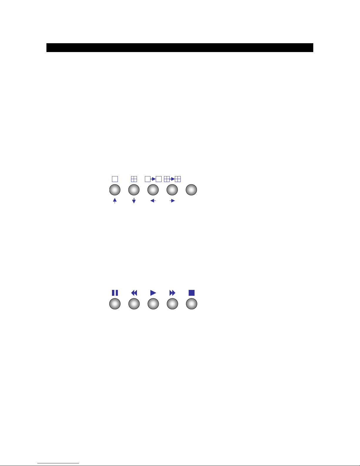
3. Screen mode control / Menu control buttons
Enter
-There are 2 modes for these buttons, either in live mode or menu control mode
-In live mode, the buttons are used to change video display mode in full screen, quad screen,
full screen page mode and quad screen page mode
-In menu control mode, the buttons are used as “up”, “down”, “left”, “right” and “Enter”
control
4. Local Playback control buttons
-These 5 buttons are used for recording playback control only
-The functions are pause, fast backward, play, fast forward, and stop

Tele
Eye III+ VX Installation Guide Page 5
Installation of
Tele
Eye III+ VX for Local Monitoring
5. Mode control buttons
Event Rec Live Play Menu
-These 5 buttons are used for switching between the control modes
-Event button: fast switch to event menu at any time
-Rec button: enable/disable normal recording at any time
-Live button: view live video at any time
-Play button: fast switch to playback log menu
-Menu button: switch to menu for system settings, recording settings and event settings etc.
6. Notification LEDs
There are 5 notification LEDs, 3 blue color and 2 red color from right to left
Event
LED Recording
LED Live
LED Play
LED Power
LED
Power LED: this LED will be ON when hard disk rack key is locked and power switch is
turned on. This LED will blink during system initiation, and remains ON after initiation.
Play LED: this LED will be ON when user press the [Play] button, it will turn OFF when the
system is in live mode
Live LED: this LED is ON indicating that video from the video out connectors are live videos.
During recording video playback, this LED turns OFF
Recording LED: this LED will turn ON when
Tele
Eye III+ VX is doing recording
Event LED: this LED will blink when event is triggered
Tele
Eye III+ VX Installation Guide Page 6
Installation of
Tele
Eye III+ VX for Local Monitoring
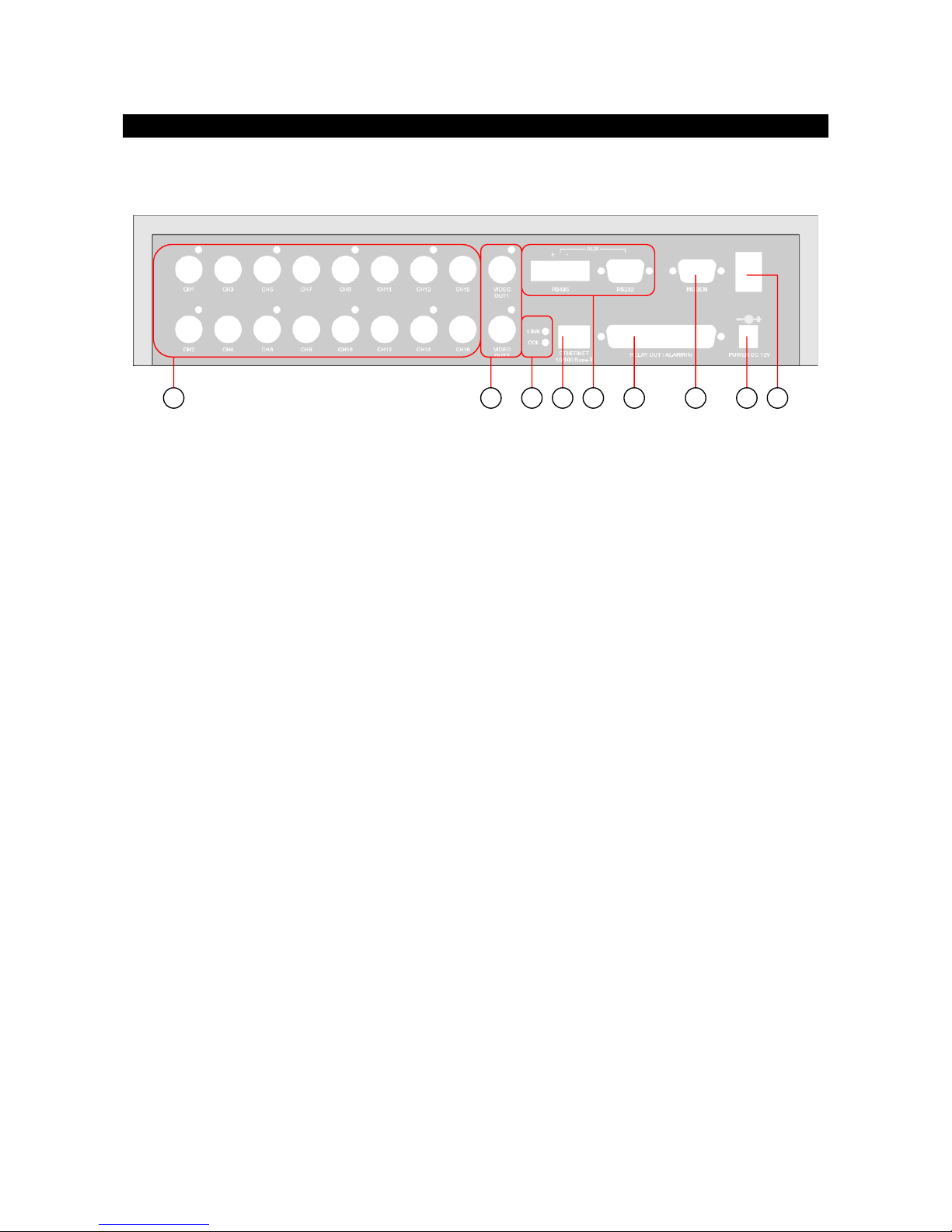
Rear Panel Descriptions
1. VIDEO INPUT Connectors
-VX–4001 / VX–4002: CH1 – CH4
-VX–8002 / VX–8004: CH1 – CH8
-VX–16004 / VX–16008: CH1 – CH16
-Standard BNC connectors for color and black and white video sources
-A composite video signal should be supplied to these connectors
2. VIDEO OUTPUT Connectors
-VIDEO OUT1 and VIDEO OUT2
-A composite video signal with 1V p-p is output from these connectors
-PAL/CCIR format with 625 lines, 50 fields per second
-NTSC/EIA format with 525 lines, 60 fields per second
3. RELAY OUT / ALARM IN Port
-4 control switches are available for all models.
-VX–4001 / VX–4002: 4 alarm ports
-VX–8002 / VX–8004: 8 alarm ports
-VX–16004 / VX–16008: 16 alarm ports
1
2
5
4
6
3
7
8
9

Tele
Eye III+ VX Installation Guide Page 7
Installation of
Tele
Eye III+ VX for Local Monitoring
-All alarm ports are NC/NO type input
-Alarm port 1 can be configured as arm/disarm input
4. Ethernet Socket (10/100 Base-T)
-This socket is used for connecting
Tele
Eye III+ VX to the corporate computer network (e.g.
LAN)
5. Collision & Link LED Status
COL LED: when on, indicates that collision is occurring on the network.
LINK LED: when on, indicates that
Tele
Eye III+ VX is connecting to the network and ready
to function.
6. AUX Port
-A DB-9 female connector of DCE format, capable of connecting to DTE such as remote
Pan/Tilt/Zoom operation
-Used for configuring the
Tele
Eye III+ VX ’s internal settings
Pin number
Definition Direction
1 CD Output
2 RXD Output
3 TXD Input
4 DTR Input
5 GND –––
6 DSR Output
7 RTS Input
8 CTS Output
9 N/A

Tele
Eye III+ VX Installation Guide Page 8
Installation of
Tele
Eye III+ VX for Local Monitoring
7. MODEM Port
-A DB-9 male connector of DTE format, capable for connecting to DCE such as modem,
ISDN terminal adaptor
Pin number
Definition Direction
1 CD Input
2 RXD Input
3 TXD Output
4 DTR Output
5 GND –––
6 DSR Input
7 RTS Output
8 CTS Input
9 N/A
8. Power Jack
-A 2.1mm D.C. power jack for the connection to the power supply (12V D.C.)
9. Switch
-A power switch to switch on or off the
Tele
Eye III+ VX transmitter
Tele
Eye III+ VX Installation Guide Page 9
Installation of
Tele
Eye III+ VX for Local Monitoring
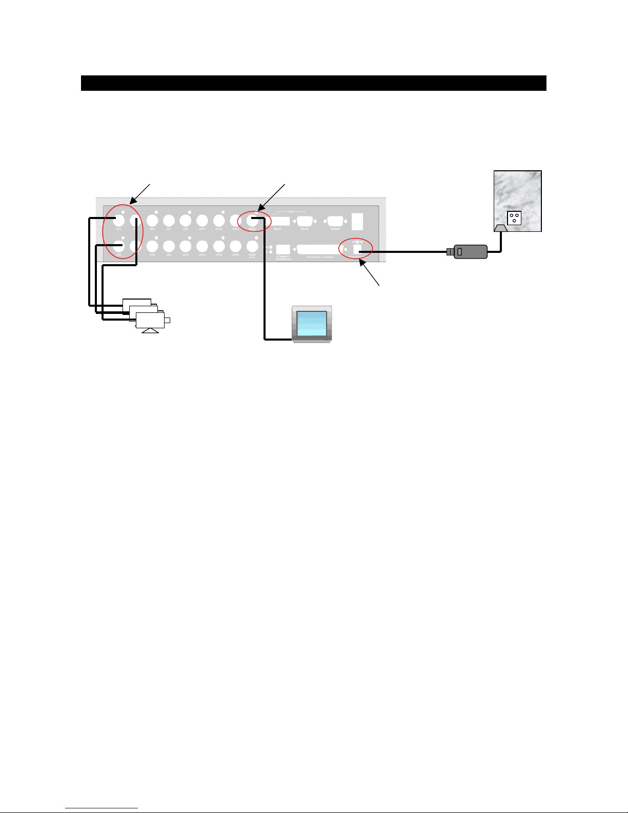
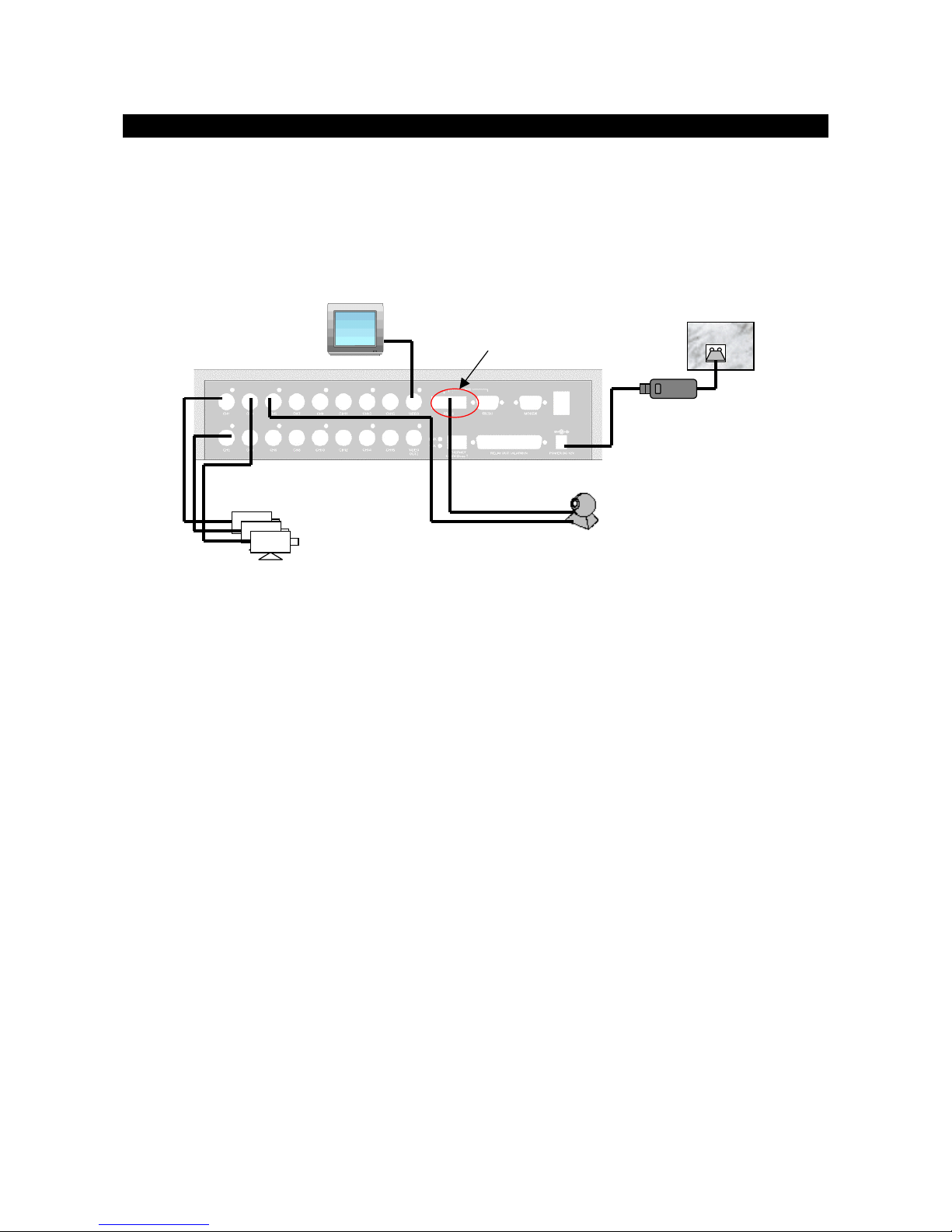
Install
Tele
Eye III+ VX for Local Video Display
Monitor
BNC cable Power Adapter
Video Cameras
BNC cables
VIDEO OUT connect to coaxial
video cable with BNC header
VIDEO IN connect to camera
with coaxial cables with BNC
header
DC power supply input with
12VDC, centre positive
Tele
Eye
III+
VX
Procedures:
1. Insert the hard disk cartridge into the hard disk tray of
Tele
Eye III+ VX
2. Using the key provided to lock the hard disk cartridge
3. Connect video cameras to input video channels with BNC cable
4. Connect the VIDEO OUT1 to a monitor using BNC cable
5. Plug the DC supply to the power jack from the power adapter
6. Switch on the
Tele
Eye III+ VX and you will see the live video on the monitor. For the
first time you use
Tele
Eye III+ VX, the live display mode is in quad mode, which means
you will see four cameras on the screen at the same time

Tele
Eye III+ VX Installation Guide Page 10
Installation of
Tele
Eye III+ VX for Local Monitoring
CAMERA 3
CAMERA 1
16:28:30
CAMERA 2
CAMERA4
7. Press the [full screen mode control] button to switch to the full screen mode. You can press
the [quad screen mode control] button again to switch back to quad mode
CAMERA 1
16:28:30
8. Press the [live camera control] button to switch to a different camera
CAMERA 3
16:28:30
Full screen mode
control button
Quad screen mode control
button
Enter
1
2
3
4
. . .

Tele
Eye III+ VX Installation Guide Page 11
Installation of
Tele
Eye III+ VX for Local Monitoring
9. Press the [page switching mode control] button to view all cameras sequentially
CAMERA 1
162830
16:28:35
CAMERA 2
16:28:45
CAMERA 4
CAMERA 3
16:28:40
Other Cameras
5 sec
5 sec
5 sec
5 sec
Page switching mode
control (full screen) button
Page switching mode
control (quad screen) button
Enter

Tele
Eye III+ VX Installation Guide Page 12
Installation of
Tele
Eye III+ VX for Local Monitoring
Install
Tele
Eye III+ VX with Alarm Sensors and Relay
Control Port
Tele
Eye III+ VX supports up to 16 alarm ports for connecting with alarm sensors, and 4 relay
ports for remote/local controls. The definitions of alarm and relay control port are shown in the
following diagram.
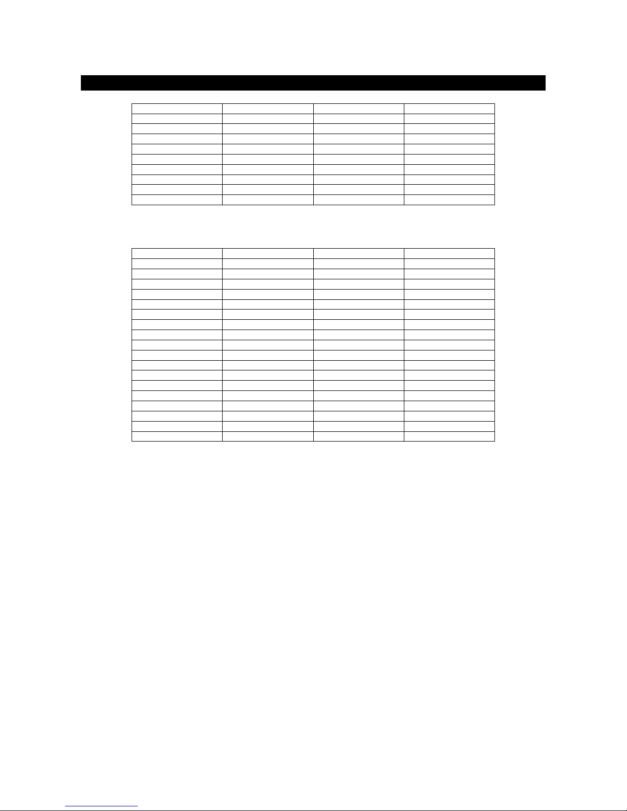
For VX-4001/ VX-4002:
Pin 1 ALARM 1 Pin 20 GND
Pin 2 ALARM 2 Pin 21 GND
Pin 3 ALARM 3 Pin 22 GND
Pin 4 ALARM 4 Pin 23 GND
Pin 5 N/C Pin 24 GND
Pin 6 N/C Pin 25 GND
Pin 7 N/C Pin 26 GND
Pin 8 N/C Pin 27 GND
Pin 9 N/C Pin 28 GND
Pin 10 N/C Pin 29 GND
Pin 11 N/C Pin 30 GND
Pin 12 N/C Pin 31 GND
Pin 13 N/C Pin 32 N/C
Pin 14 N/C Pin 33 N/C
Pin 15 RELAY 0a Pin 34 RELAY 0b
Pin 16 RELAY 1a Pin 35 RELAY 1b
Pin 17 RELAY 2a Pin 36 RELAY 2b
Pin 18 RELAY 3a Pin 37 RELAY 3b
Pin 19 N/C
For VX-8002 / VX-8004:
Pin 1 ALARM 1 Pin 20 GND
Pin 2 ALARM 2 Pin 21 GND
Pin 3 ALARM 3 Pin 22 GND
Pin 4 ALARM 4 Pin 23 GND
Pin 5 ALARM 5 Pin 24 GND
Pin 6 ALARM 6 Pin 25 GND
Pin 7 ALARM 7 Pin 26 GND
Pin 8 ALARM 8 Pin 27 GND
Pin 9 N/C Pin 28 GND
Tele
Eye III+ VX Installation Guide Page 13
Installation of
Tele
Eye III+ VX for Local Monitoring
Pin 10 N/C Pin 29 GND
Pin 11 N/C Pin 30 GND
Pin 12 N/C Pin 31 GND
Pin 13 N/C Pin 32 N/C
Pin 14 N/C Pin 33 N/C
Pin 15 RELAY 0a Pin 34 RELAY 0b
Pin 16 RELAY 1a Pin 35 RELAY 1b
Pin 17 RELAY 2a Pin 36 RELAY 2b
Pin 18 RELAY 3a Pin 37 RELAY 3b
Pin 19 N/C
For VX-16004 / VX-16008:
Pin 1 ALARM 1 Pin 20 GND
Pin 2 ALARM 2 Pin 21 GND
Pin 3 ALARM 3 Pin 22 GND
Pin 4 ALARM 4 Pin 23 GND
Pin 5 ALARM 5 Pin 24 GND
Pin 6 ALARM 6 Pin 25 GND
Pin 7 ALARM 7 Pin 26 GND
Pin 8 ALARM 8 Pin 27 GND
Pin 9 ALARM 9 Pin 28 GND
Pin 10 ALARM 10 Pin 29 GND
Pin 11 ALARM 11 Pin 30 GND
Pin 12 ALARM 12 Pin 31 GND
Pin 13 ALARM 13 Pin 32 ALARM 14
Pin 14 ALARM 15 Pin 33 ALARM 16
Pin 15 RELAY 0a Pin 34 RELAY 0b
Pin 16 RELAY 1a Pin 35 RELAY 1b
Pin 17 RELAY 2a Pin 36 RELAY 2b
Pin 18 RELAY 3a Pin 37 RELAY 3b
Pin 19 N/C
Tele
Eye III+ VX Installation Guide Page 14
Installation of
Tele
Eye III+ VX for Local Monitoring
Install
Tele
Eye III+ VX with Telemetry Control
As
Tele
Eye III+ VX built with a RS485 port, you can connect this port to Pan/Tilt/Zoom cameras.
The connection diagram is shown below.
Monitor
BNC cable
Power Adapter
Video Cameras
BNC cables
RS485 port connect with
camera
Tele
Eye
III+
VX
2 wire RS485 bus P/T/Z camera
BNC cable
Note: RS485 and RS232 AUX port are shared port in
Tele
Eye III+ VX. Only connect to one port
at a time. Connecting both ports at the same time will cause both ports malfunction.

Tele
Eye III+ VX Installation Guide Page 15
Menu Operation
3
MENU OPERATION
Menu Structure
The system setup and operation of
Tele
Eye III+ VX is controlled through menus. The overall
menu tree is shown in the following diagram. The function of each menu will be explained later in
this section.
[ MAIN MENU ]
DISPLAY SETUP . . .
ALARM SETUP . . .
SWITCH SETUP . . .
RECORDING SETUP . . .
TRANSMITTER SETUP . . .
EVENT SETUP . . .
ARM/DISARM SETUP . . .
PASSWORD SETUP . . .
EXIT
[ DISPLAY SETUP ]
CAMERA SETUP . . .
VIDEO SETUP . . .
OSD COLOR BLUE
TIME DISPLAY TOP LEFT
CAMERA NAME DISPLAY BOTTOM
PAGE SWITCHING (SEC) 1
BACK
[ALARM SETUP]
ALARM NAME . . .
ALARM TYPE . . .
ALARM INSTALLED -2345678--------
ALARM ASSOCIATE CAMERA . . .
BACK
[ SWITCH SETUP ]
SWITCH NAME . . .
SWITCH TYPE . . .
SWITCH ON/OFF . . .
BACK
[ RECORDING SETUP ]
DISK INFORMATION . . .
RECORDING MODE . . .
NORMAL RECORDING . . .
PRE-ALARM RECORDING . . .
PROGRAMMABLE RECORDING . . .
AUDIO RECORDING . . .
RECORDING RESOLUTION MEDIUM
RECORDING QUALITY EXCELLENT
BACK
[ TRANSMITTER SETUP ]
GENERAL SETUP . . .
NETWORK SETUP . . .
ADV. DISK SETUP . . .
BACK
SECTION

Tele
Eye III+ VX Installation Guide Page 16
Menu Operation
[ EVENT SETUP]
ALARM EVENT . . .
MOTION EVENT . . .
VIDEO LOSS EVENT . . .
DISK FULL EVENT . . .
SYSTEM FAILURE EVENT . . .
MOTION CAMERA SETUP . . .
EVENT SWITCH SETUP . . .
DIAL BACK SETUP . . .
EMAIL SETUP . . .
BACK
[ ARM DISARM SETUP ]
DISARM TYPE (ALARM 1) NORMAL OPEN
ASSOCIATE ALARM EVENT YES
ASSOCIATE MOTION EVENT YES
BACK
[ PASSWORD SETUP ]
ENABLE SETUP MENU PASSWRD NO
ENABLE PLAYBACK MENU PASSWRD NO
ENABLE EVENT MENU PASSWRD NO
ENABLE RECORDING MENU PASSWRD NO
CHANGE PASSWORD ******
BACK
Main Menu
[ MAIN MENU ]
DISPLAY SETUP . . .
ALARM SETUP . . .
SWITCH SETUP . . .
RECORDING SETUP . . .
TRANSMITTER SETUP . . .
EVENT SETUP . . .
ARM/DISARM SETUP . . .
PASSWORD SETUP . . .
EXIT
This manual suits for next models
6
Table of contents
Other TeleEye Transmitter manuals


Popular Transmitter manuals by other brands


Bosch
Bosch SEC-RFPB60M-433 installation manual

KLAY-INSTRUMENTS
KLAY-INSTRUMENTS 2000-SAN Series instruction manual

Emerson
Emerson Rosemount 3051 quick start guide

Seneca
Seneca Z202-LP installation instructions

Elpas
Elpas 5-LW200037-1 user guide

Akron Brass
Akron Brass STYLE 3600 Installation and operating instructions

Broadcast Warehouse
Broadcast Warehouse TX 150/300 Technical manual

Comnet
Comnet FVT1C1BM1-M Installation and operation manual

Bosch
Bosch CRS-NC-S37L operating instructions

Baumer
Baumer CTL installation manual

Broadata
Broadata LBC-H-T-LPB-Lite Safety instructions

Berker
Berker 85607100 Operation instructions