Telemark Cryogenics CRYO-CHILLER User manual
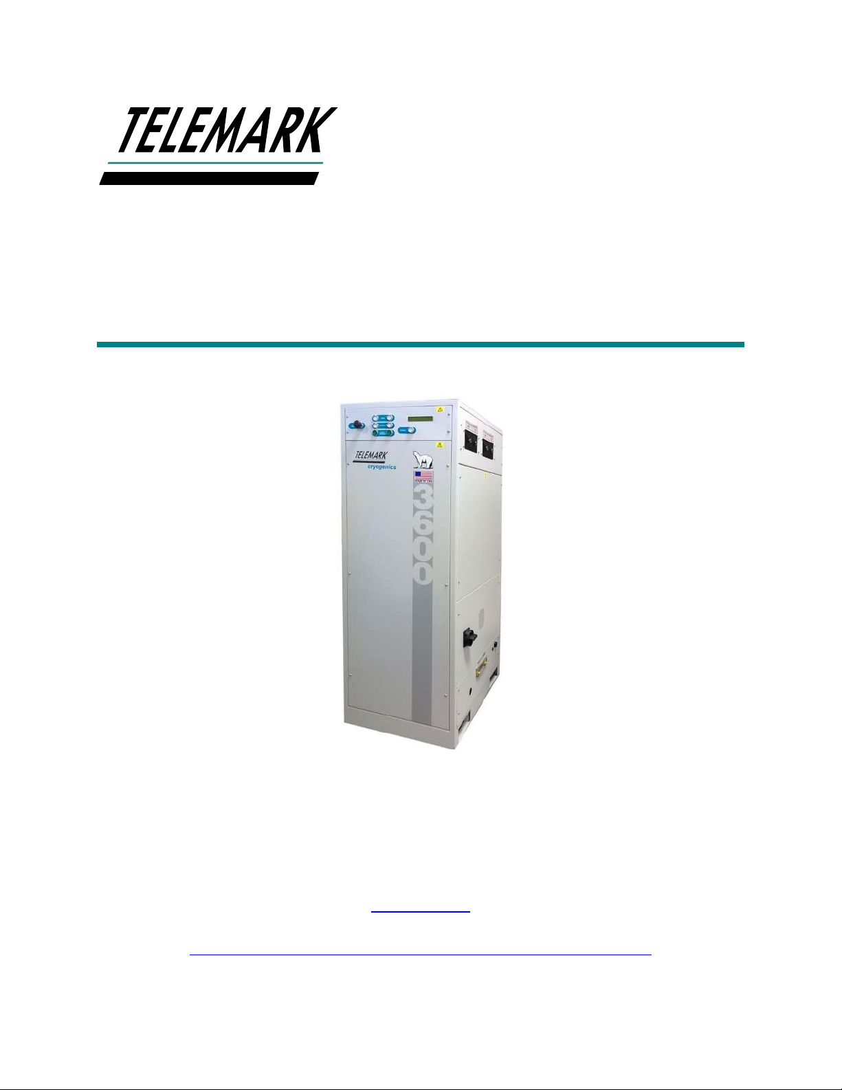
MICROPROCESSOR BASED WATER VAPOR
CRYO-CHILLER
INSTRUCTION MANUAL
Part No 19-0001-00
Models Covered in this manual 1200, 1800, 1800EXT, 2400, 3000, 3600, 4800
Copyright © Telemark Cryogenics, 1998-2021 –All rights reserved
Manual Rev 1.0.9 March 2021
telemark.com
Download the current version of this manual at
https://telemark.com/water-vapor-cryochiller/cryochiller-models/
Brand and product names are trademarks or registered trademarks of their respective companies
Cryogenics

Cryogenics Microprocessor Based Cryochillers INTRODUCTION
telemark.com 2 of 81
Rev 1.0.9
TABLE OF CONTENTS
1INTRODUCTION..........................................................................7
1.1 SAFETY WARNINGS ...........................................................................7
1.2 WARRANTY........................................................................................11
1.3 USER RESPONSIBILITY....................................................................12
1.4 INTENDED USE OF THE EQUIPMENT .............................................12
1.5 STANDARDS ......................................................................................13
2SPECIFICATIONS .....................................................................14
2.1 GAS CWP CHART..............................................................................17
2.2 ENVIRONMENTAL CONDITIONS......................................................17
2.3 RECOMMENDED BREAKER AND WIRE SIZE .................................18
2.4 PHYSICAL DIMENSIONS...................................................................19
3INSTALLATION .........................................................................20
3.1 UNPACKING AND INSPECTION .......................................................22
3.2 SYSTEM PRESSURE.........................................................................23
3.3 LOCATION..........................................................................................23
3.4 PANEL REMOVAL..............................................................................23
3.5 WATER CONNECTIONS....................................................................24
3.6 REFRIGERANT LINE CONNECTION ................................................26
3.6.1 Refrigerant Line Installation Notes....................................................................... 29
3.7 MAIN ELECTRICAL CONNECTIONS.................................................32
3.7.1 Transformer Connections .................................................................................... 33
3.8 REMOTE CONNECTIONS .................................................................35
3.8.1 Digital Remote Control. ........................................................................................ 35
3.8.2 Analogue Output voltage ..................................................................................... 38
3.9 ETHERNET COMMUNICATION.........................................................39
3.9.1 Ethernet (Laptop) set up ...................................................................................... 40
3.9.2 Commands Available when Using Ethernet, RS232/485 Control........................ 42
3.9.3 Using TCPIP-RS232/485/Ethernet GUI ............................................................... 43
3.9.4 GUI Button/Screen Functions .............................................................................. 43

Cryogenics Microprocessor Based Cryochillers INTRODUCTION
telemark.com 3 of 81
Rev 1.0.9
3.9.5 “cal2309” Screen (User Configuration screen) .................................................... 45
3.9.6 USING THE TCPIP-RS232/485 PROGRAM....................................................... 48
4OPERATION..............................................................................58
4.1 CONTROLS AND DISPLAYS .............................................................58
4.1.1 LCD Display ......................................................................................................... 58
4.2 SCROLL PUSH BUTTON ...................................................................60
4.3 PUSH BUTTONS ................................................................................60
4.3.1 COOL Push Button(s)/Indicators(s) ..................................................................... 60
4.3.2 STOP/RESET Push Button.................................................................................. 60
4.4 OPERATION .......................................................................................61
4.4.1 Turn on the main ISO isolator .............................................................................. 61
4.4.2 Turning the Unit On.............................................................................................. 61
4.4.3 Standby ................................................................................................................ 61
4.4.4 Cool...................................................................................................................... 61
4.4.5 Defrost.................................................................................................................. 61
4.4.6 Defrost Recovery Period...................................................................................... 61
4.5 NORMAL OPERATING RANGES.......................................................62
5TROUBLE SHOOTING GUIDE..................................................63
5.1 TROUBLE SHOOTING .......................................................................63
5.2 REFRIGERATION LEAKS ..................................................................63
5.3 ALARM CODES/MESSAGES .............................................................63
5.4 SAFETY SYSTEMS ............................................................................64
5.4.1 Hardware Safety systems .................................................................................... 64
5.5 TROUBLE SHOOTING GUIDE...........................................................65
5.6 THE USE OF “TOP-OFF” GAS CHARGES ........................................69
5.7 EMERSON (COPELAND™) COMPRESSOR.....................................69
5.7.1 Compressor Diagnostics ...................................................................................... 71
6DECOMMISSIONING.................................................................75
7DESIGN OF CRYO-COILS ........................................................77
8CHINESE SAFETY DATA SHEET.............................................80

Cryogenics Microprocessor Based Cryochillers INTRODUCTION
telemark.com 4 of 81
Rev 1.0.9
LIST OF FIGURES
Figure 3-1, Removing Unit from Transportation Pallet...............................................................22
Figure 3-2, Pressure Gauge......................................................................................................23
Figure 3-3, Service Panel..........................................................................................................24
Figure 3-4, Water flow Requirements........................................................................................25
Figure 3-5, Position of Hand Valves ..........................................................................................26
Figure 3-6, Refrigerant Line Connections..................................................................................27
Figure 3-7, Access Valve ..........................................................................................................28
Figure 3-8, Refrigerant Manifold................................................................................................28
Figure 3-9, Refrigerant Line Insulation ......................................................................................31
Figure 3-10, Metal O-ring Removal Tool ...................................................................................32
Figure 3-11, Main Isolator Wiring ..............................................................................................33
Figure 3-12, Transformer Tapings.............................................................................................34
Figure 3-13, 37-Way Amphenol™ Connector, Front view .........................................................37
Figure 3-14, Ethernet cable (crossed) .......................................................................................39
Figure 3-15, Network Connection Window ................................................................................40
Figure 3-16, Network Properties ...............................................................................................40
Figure 3-17, TCP/IP ..................................................................................................................41
Figure 3-18, Set up for TCP/IP..................................................................................................41
Figure 3-19, TCP/IP GUI...........................................................................................................43
Figure 3-20, Ethernet TCP/IP and RS232/485 Help Screens ....................................................45
Figure 3-21, “cal2309” Screen Setup ........................................................................................46
Figure 3-22, Change Com Port .................................................................................................49
Figure 3-23, Select Com Port....................................................................................................49
Figure 3-24, Com Connection Shown .......................................................................................50
Figure 3-25, Enter rip ................................................................................................................50
Figure 3-26 Display IP Address.................................................................................................51
Figure 3-27, Change Remote Host............................................................................................51
Figure 3-28, Go to IP Properties ...............................................................................................52
Figure 3-29, Check IP Addresses..............................................................................................52
Figure 3-30, Parameter Setup...................................................................................................53
Figure 3-31, Select IP Address for Changing ............................................................................53

Cryogenics Microprocessor Based Cryochillers INTRODUCTION
telemark.com 5 of 81
Rev 1.0.9
Figure 3-32, Enter new IP address............................................................................................54
Figure 3-33, Disconnect TCP/IP................................................................................................55
Figure 3-34, Change Remote Host IP address..........................................................................55
Figure 3-35, Disconnect TCP/IP Again......................................................................................56
Figure 3-36, Check first three IP numbers.................................................................................57
Figure 3-37, Connect to Remote Host.......................................................................................57
Figure 4-1, Front Panel Push Buttons (Single Coil Unit Shown) ................................................58
Figure 4-2, LCD Display, Wait...................................................................................................58
Figure 4-3, LCD Display, Pre-Cool............................................................................................59
Figure 4-4, , LCD Display, Ready..............................................................................................59
Figure 4-5, LCD Display, Cool...................................................................................................59
Figure 5-1, “OVER PRESSURE” Alarm Message .....................................................................64
Figure 5-2, “E1” With Fault Shown as “DP HIGH” .....................................................................64
Figure 5-3, Emerson Compressor Front Panel Fault Code LED’s .............................................70
Figure 5-4, Emerson Compressor Internal Electronic Parts.......................................................70

Cryogenics Microprocessor Based Cryochillers INTRODUCTION
telemark.com 6 of 81
Rev 1.0.9
LIST OF TABLES
Table 2-1, Model 1200, 1800, 1800EXT, 2400 Specifications ...................................................15
Table 2-2, Model 3000, 3600, 4800 Specifications....................................................................16
Table 2-3, Current Models Gas CWP Chart ..............................................................................17
Table 2-4, Discontinued Models Gas CWP Chart......................................................................17
Table 2-5, Environmental Conditions ........................................................................................17
Table 2-6, Recommended Breaker and Wire Size ....................................................................18
Table 2-7, Physical Dimensions ................................................................................................19
Table 3-1, Cryochiller Recommended Circuit Breaker value and Wire Size ..............................33
Table 3-2, Pin Connection for 37-way Amphenol Connector .....................................................37
Table 3-3, Volts vs. Temp Analog Output..................................................................................38
Table 3-4, Write Serial Commands ...........................................................................................42
Table 3-5, Read Serial Commands ...........................................................................................42
Table 4-1, Display Mnemonics and Their Meaning....................................................................59
Table 4-2, Normal Operating Ranges........................................................................................62
Table 5-1, Listing of Alarm Messages and Error Codes ............................................................64
Table 5-2, Troubleshooting Guide.............................................................................................68
Table 5-3, Emerson LEDs.........................................................................................................74
Table 7-1, Coil Surfaces and Theoretical Pumping ...................................................................78

Cryogenics Microprocessor Based Cryochillers INTRODUCTION
telemark.com 7 of 81
Rev 1.0.9
1 INTRODUCTION
1.1 SAFETY WARNINGS
THE PHRASE WARNING IS USED WHERE THERE IS A HIGH
PROBABILITY OF PERSONAL INJURY OR DEATH SHOULD
THE PROVISIONS HIGHLIGHTED BE IGNORED. IT IS THE
DUTY OF BOTH THE INSTALLER/OWNER AND OPERATOR
OF THE EQUIPMENT TO BE FAMILIAR AND COMPETENT
WITH THE OPERATION AND USES OF THE PRODUCT.
HELP MAY BE SOUGHT FROM THE MANUFACTURER.

Cryogenics Microprocessor Based Cryochillers INTRODUCTION
telemark.com 8 of 81
Rev 1.0.9
WARNING
1) The system contains specific hazards, which present a
significant danger to personal safety:
(a) High voltage electrical components and high-pressure
refrigerant gases, which are a significant frostbite
hazard.
(b) Refrigerant gases, which will cause asphyxiation in
confined areas.
(c) Refrigerant gases, which if exposed to high
temperatures decompose to form very toxic by-
products –never smoke in the vicinity of a UNIT
or any other similar system including the gas
cylinders.
(d) Water in close proximity to high voltage electricity.
(e) Hot and cold surfaces which represent a significant
burn / frostbite hazard.
WARNING
The system contains gases under pressure, which may
constitute both a frostbite hazard and a burn hazard.
Refrigerant gases are known asphyxiates and are mildly
narcotic. Precautions must be taken, and work must only be
carried out by suitably qualified personnel.
WARNING
Removal of any panels other than the front door will expose
the operator to high voltage components, which may result
in a fatal electrocution.
WARNING
During installation there is the potential to be exposed to
high voltage components (up to 400v ac), which may result
in a fatal electrocution.
Cryogenics Microprocessor Based Cryochillers INTRODUCTION
telemark.com 9 of 81
Rev 1.0.9
WARNING
Units must always be operated with a suitable ground/earth
line. Failure to comply may result in fatal electrocution.
Never tamper with or remove any ground/earth connection
from inside of the machine.
WARNING
Isolate system before connection. Ensure the connection
cable used is compliant with local electrical requirements.
Cabling within the unit is tri-rated to CSA/UL/CE norms.
There must be three power wires and one ground wire;
there is no neutral line. Feed cable through gland and
terminate at main system isolator, having first removed the
protective cover. Ground the UNIT at primary ground point.
WARNING
Failure to replace isolator cover exposes operators to
potentially fatal electrocution. It is essential this primary
protection always be in place before the system is
energized.
WARNING
Always isolate the system through the main circuit breaker
before attaching the remote control. When in remote
operation take additional care to prevent personal injury.
WARNING
Failure to leak test the system as a whole, may result in the
catastrophic release of refrigerant, which presents a very
high risk from frostbite and or asphyxiation. See emergency
shutdown procedures and material safety data sheet for
guidance.
Cryogenics Microprocessor Based Cryochillers INTRODUCTION
telemark.com 10 of 81
Rev 1.0.9
WARNING
The refrigeration system contains a mixed blend of
refrigerants and polio-ester oil. These do not present
acute health risks, but it is essential that the following
basic precautions are followed:
a. Always wear eye protection.
b. Always wear surgical type rubber or latex gloves.
CAUTION
CAUTION
Telemark will not be responsible or liable for either direct
or consequential personal injury or loss claims arising
from the misuse of the product.
CAUTION
If the equipment is used in a manner not specified by the
manufacturer, the protection provided by the equipment
may by impaired
CAUTION
It is the responsibility of the user to make sure all local,
county, state and national codes, regulations, rules, and
laws related to safety and safe operating conditions are
meet for each installation. The safety of any system
incorporating the equipment is the responsibility of the
assembler of the system.
The phrase “Caution”indicates a risk of damage to
the product or associated plant and machinery if the
provisions are not followed carefully.

Cryogenics Microprocessor Based Cryochillers INTRODUCTION
telemark.com 11 of 81
Rev 1.0.9
CAUTION - HOT SURFACE
High temperatures are generated during normal
operation. Avoid contact with exposed pipework as this
can get hot during normal operation.
CAUTION - COLD SURFACE
Freeze Burn Risk. Very low temperatures generated
during normal operation. Avoid contact with exposed
pipework.
CAUTION - PRESURISED GAS
Unit contains pressurized gas. Do not open hand valves
until system is connected to a Cryo-coil, which has been
checked for leaks. Do not connect the system to other
systems unless their design and application has been
approved by the manufacturer
CAUTION - HAND VALVES
Closure of the hand valves while the system is at
cryogenic temperatures may damage the valve seats and
invalidate the systems warranty. It must only be
attempted on a cryogenically cold system in the case of
an emergency, which is causing gross leakage from the
Cryo-coil or refrigerant lines.
1.2 WARRANTY
Telemark Cryogenics Cryochiller products are warranted to be free from defects in
materials and/or workmanship under normal usage until warranty effective date listed on
serial number label. Telemark Cryogenics’obligation under this warranty is limited to the
repair or replacement, at its option, of any parts, which upon examination at the
Telemark Cryogenics factory or by an authorized sales/service representative, shall
appear to have become defective. Correction of defects by repair or replacement shall
be either at the Telemark factory or in-situ by an authorized service representative. The

Cryogenics Microprocessor Based Cryochillers INTRODUCTION
telemark.com 12 of 81
Rev 1.0.9
location of repair shall be at the discretion of Telemark Cryogenics. Repairs carried out
at Telemark Cryogenics factory shall be FOB Telemark factory and shall constitute
fulfilment of obligations to the purchaser. All transportation costs for defective parts or
products shall be borne by the purchaser. Telemark Cryogenics will not be liable for
loss, damage, or other expenses directly or indirectly arising from the use of its products
or from any other causes. Telemark assumes no liability for expenses or repairs made
outside of its factory by non-authorized personnel.
All claims on account of defective material or workmanship shall be deemed waived
unless made in writing within the warranty period. The foregoing warranty is in lieu of all
other warranties expressed or implied. Telemark neither assumes nor authorizes any
other person to assume any other obligation or liabilities in conjunction with the sale of
its products. This warranty shall be void if the equipment has been subject to misuse,
negligence, or application outside of recommended operating environment or
conditions. The warranty will also be invalidated if the identification numbers of the
system have been altered, defaced, or removed.
The warranty is not intended to supplant any statutory rights the purchaser may have.
Unit start and end dates are printed on the unit’s serial number label.
1.3 USER RESPONSIBILITY
The user is responsible for proper installation, operation and ordinary maintenance of
the equipment following the procedures in this manual. The warranty may be void if the
equipment is improperly installed. Alteration of the design and or any function of the
equipment voids the warranty and is entirely the responsibility of the user.
Telemark will not be held responsible or liable for either director consequential personal
injury or loss claims arising from the misuse of the product
The user should read this manual in its entirety before carrying out any work and or
operation of a Telemark Cryochiller.
1.4 INTENDED USE OF THE EQUIPMENT
Water vapor Cryochiller is a device that improves the performance of vacuum pumping
due to the efficient trapping of water vapor in the chamber.
Classically a Cryochiller is used with an evaporative surface (Meissner/cryo-coil), which
is located within the vacuum chamber. When in this configuration a Telemark
Cryochiller is an ultrahigh performance vacuum pump capable of pumping water vapor
and other condensable gases at speeds far more than conventional vacuum pumps.
A Telemark Cryochiller couples speed with a sophisticated computer control package
which includes a simple and adaptable user interface with isolated inputs/outputs and
Ethernet comms package as standard. RS232 and RS485 serial communication options
are available.

Cryogenics Microprocessor Based Cryochillers INTRODUCTION
telemark.com 13 of 81
Rev 1.0.9
The ranges of tasks to which your Cryochiller can be applied are not limited to pumping
water vapor in vacuum. Many are used as substrate coolers (chuck coolers) or other
applications where a continuous level of high-power cooling in the range –100 to –
150oc is required.
1.5 STANDARDS
The device is compatible in terms of electromagnetic compatibility and safety standards.
Applicable standards:
EMC: DIRECTIVE 2014/30/UE - STANDARD EN 61326-1:2013
LVD: DIRECTIVE 2014/35/EU - STANDARD EN 61010-1:2011
And applicable causes of the standard: EN 378-2:2008

Cryogenics Microprocessor Based Cryochillers SPECIFICATIONS
telemark.com 14 of 81
Rev 1.0.9
2 SPECIFICATIONS
Specifications for models 1200, 1800, 1800EXT, 2400, 3000, 3600 and 4800 are on the
following pages.

Cryogenics Microprocessor Based Cryochillers SPECIFICATIONS
telemark.com 15 of 81
Rev 1.0.9
Model 1200
Model 1800
Model 1800EXT
Model 2400
Maximum Load (Watts)
1,200
1,800
1,800
2400
Typical Pumping Speed
(l/sec)
65,000
100,000
100,000
135,000
Ultimate Vacuum
2 x10⁻⁸ mbar
(2 x10⁻⁶Pa)
2 x10⁻⁸ mbar
(2 x10⁻⁶Pa)
2 x10⁻⁸ mbar
(2 x10⁻⁶Pa)
2 x10⁻⁸ mbar
(2 x10⁻⁶Pa)
Weight (Kg)
193 (432 lbs)
243 (536 lbs)
243 (536 lbs)
243 (536 lbs)
Size inch (mm)
L
W
H
24 (559)
22 (610)
59.5 (1511)
24 (559)
22 (610)
59.5 (1511)
24 (559)
22 (610)
59.5 (1511)
24 (559)
22 (610)
59.5 (1511)
Power supply
380-444VAC 3 ph
50Hz
460VAC 3 ph 60 Hz
200-230VAC 3 Ph
50/60 Hz
380-444VAC 3 ph
50Hz
460VAC 3 ph 60
Hz
200-230VAC 3 Ph
50/60 Hz
380-444VAC 3 ph
50Hz
460VAC 3 ph 60 Hz
200-230VAC 3 Ph
50/60 Hz
380-444VAC 3 ph
50Hz
460VAC 3 ph 60 Hz
200-230VAC 3 Ph
50/60 Hz
Wire/Cable Connection
3 Phase + Ground
(Earth)
3 Phase +
Ground (Earth)
3 Phase + Ground
(Earth)
3 Phase + Ground
(Earth)
Full Load Current draw @
60 Hz (Amps)
@200-230VAC
@380-440VAC
20
10
30
15
30
15
40
20
Start Up Max
Current Draw @ 60 Hz
(Amps)
@200-230VAC
@380-440
30
15
60
30
60
30
60
30
Compressor Horsepower
(HP)
4.5 (3.35kW)
7.5 (5.59kW)
7.5 (5.59kW)
10 (7.46kW)
Water Requirements (l/min)
@ 15°C
@ 25°C
@ 32°C
5
10
20
5
10
20
5
10
20
6
12
30
Water Connections
All Models ¾” NPT Female
Water Resistivity
All Models >0.1MΩ Chloride Free
Water pH
All Models 6.5 - 8
Refrigeration Connections
½” Metal Seal
½” Metal Seal
½” Metal Seal
½” Metal Seal
Max Coil Length (Meters)
Using ½” Cu tube
20 (65.6 ft)
25 (82 ft)
25 (82 ft)
35 (114.8 ft)
Max Surface area (M2)
0.79 (≈8.57 ft2)
0.99 (≈10.72 ft2)
0.99 (≈10.72 ft2)
1.39 (≈15 ft2)
*Avg. Cool Time (mins)
2-5
2-5
2-5
2-5
*Avg. Defrost Time (mins)
2-4
2-4
2-4
2-4
ΔT Coil in/Coil Out (°C)
≈5
≈5
≈5
≈5
Digital Remote Connections
Input Voltage range
18-24VDC
(30VDC MAX)
18-24VDC
(30VDC MAX)
18-24VDC (30VDC
MAX)
18-24VDC (30VDC
MAX)
Digital Remote Connections
Output Voltage range
Relay contact
closure 200 VAC
or 100VDC Max at
300mA
Relay contact
closure 200 VAC
or 100VDC Max
at 300mA
Relay contact
closure 200 VAC or
100VDC Max at
300mA
Relay contact
closure 200 VAC or
100VDC Max at
300mA
Balance Pressure Range as
Shipped from Telemark
USA facility (PSI) @20°C
(hand valves closed)
270-300
(1.86-2.07MPa)
220-250
(1.51-1.72MPa)
180-210
(1.24-1.45MPa)
190-220
(1.31-1.52MPa)
Table 2-1, Model 1200, 1800, 1800EXT, 2400 Specifications

Cryogenics Microprocessor Based Cryochillers SPECIFICATIONS
telemark.com 16 of 81
Rev 1.0.9
Model 3000
Model 3600
Model 4800
Maximum Load (Watts)
3000
3,600
4,800
Typical Pumping Speed
(l/sec)
165,000
200,000
275,000
Ultimate Vacuum
2 x10⁻⁸ mbar
(2 x10⁻⁶Pa)
2 x10⁻⁸ mbar
(2 x10⁻⁶Pa)
2 x10⁻⁸ mbar
(2 x10⁻⁶Pa)
Weight (Kg)
384 (845 lbs)
412 (930 lbs)
433 (955 lbs)
Size inch (mm)
L
W
H
35.3 (897)
23.6 (897)
70.25 (1784)
35.3 (897)
23.6 (897)
70.25 (1784)
35.3 (897)
23.6 (897)
70.25 (1784)
Power supply
380-444VAC 3 ph
50Hz
460VAC 3 ph 60 Hz
200-230VAC 3 Ph
50/60 Hz
380-444VAC 3 ph
50Hz
460VAC 3 ph 60 Hz
200-230VAC 3 Ph
50/60 Hz
380-444VAC 3 ph
50Hz
460VAC 3 ph 60 Hz
200-230VAC 3 Ph
50/60 Hz
Wire/Cable Connection
3 Phase + Ground
(Earth)
3 Phase + Ground
(Earth)
3 Phase + Ground
(Earth)
Full Load Current draw @ 60
Hz (Amps)
@200-230VAC
@380-440VAC
50
25
60
30
75
37
Start Up Max
Current Draw @ 60 Hz
(Amps)
@200-230VAC
@380-440
60
30
85
45
100
60
Compressor Horsepower
(HP)
13 (9.69kW)
15 (11.19kW)
20 (14.91kW)
Water Requirements (l/min)
@ 15°C
@ 25°C
@ 32°C
6
12
30
8
16
30
10
18
32
Water Connections
¾” NPT Female
Water Resistivity
All Models >0.1MΩ Chloride Free
Water pH
All Models 6.5 - 8
Refrigeration Connections
½” Metal Seal
½” Metal Seal
½” Metal Seal
Max Coil Length (Meters)
Using ½” Cu tube
40 (131.2 ft)
50 (164.0 ft)
65 (213.3 ft)
Max Surface area (M2)
1.59 (≈17.1 ft2)
1.99 (≈21.42 ft2)
2.52 (≈27.13 ft2)
*Avg. Cool Time (mins)
2-5
2-5
2-5
*Avg. Defrost Time (mins)
2-4
2-4
2-4
ΔT Coil in/Coil Out (°C)
≈5
≈5
≈5
Digital Remote Connections
Input Voltage range
18-24VDC
(30VDC MAX)
18-24VDC
(30VDC MAX)
18-24VDC
(30VDC MAX)
Digital Remote Connections
Out Voltage range
Relay contact
closure 200 VAC
or 100VDC Max at
300mA
Relay contact
closure 200 VAC
or 100VDC Max at
300mA
Relay contact
closure 200 VAC
or 100VDC Max at
300mA
Balance Pressure Range as
shipped from Telemark USA
facility (PSI) @20°C
(hand valves closed)
250-280
(1.72-1.93MPa)
250-280
(1.72-1.93MPa)
250-280
(1.72-1.93MPa)
Table 2-2, Model 3000, 3600, 4800 Specifications

Cryogenics Microprocessor Based Cryochillers SPECIFICATIONS
telemark.com 17 of 81
Rev 1.0.9
IMPORTANT.The above performance figures are based for a unit running at
60Hz mains power frequency. For units running on 50 Hz mains frequency
the figures above need to be de-rated by 0.83.
2.1 GAS CWP CHART
Current Production Models
Mass (kg)
GWP
CO2 tons eq
1200
2.94
3840
11.29
1800
3.50
3758
13.156
2400
3.56
3877
13.802
3000
5.55
4569
25.357
3600
5.15
4489
23.118
Top Off
0.83
5512
4.575
Table 2-3, Current Models Gas CWP Chart
Discontinued Models
Mass (kg)
GWP
CO2 tons eq
1000
3.54
3842
13.59
2000
4.74
3886
18.42
3500
5.83
4330
25.24
Table 2-4, Discontinued Models Gas CWP Chart
2.2 ENVIRONMENTAL CONDITIONS
Environmental conditions for all models.
Parameter
Value
Type
Indoor use
Altitude
Up to 2000m
Temperature range (°C)
5 - 40
Humidity (%Rh)
Maximum relative 80% for temperatures up to 31 ⁰C
decreasing linearly to 50% relative humidity at 40 ⁰C
Mains supply voltage
fluctuations
Up to 10% of the nominal voltage
Pollution degree
2
Overvoltage category
II
Table 2-5, Environmental Conditions

Cryogenics Microprocessor Based Cryochillers SPECIFICATIONS
telemark.com 18 of 81
Rev 1.0.9
2.3 RECOMMENDED BREAKER AND WIRE SIZE
Recommended circuit breaker values and wire size for cryochillers.
200-230VAC Vac Three-Phase
Nominal current
rating[A]
Fuse
Rating [A]
Minimum copper
wire
AWG/mm2
Cable Type
(recommended)
30
70
8 / 10
H07RN-F 450/750V 4G10
50
100
6 / 16
H07RN-F 450/750V 4G16
60
125
4 / 25
H07RN-F 450/750V 4G25
380-444VAC Three-Phase
15
30
14 / 2.5
H07RN-F 450/750V 4G2.5
25
45
10 / 6
H07RN-F 450/750V 4G6
30
60
10 / 6
H07RN-F 450/750V 4G6
Table 2-6, Recommended Breaker and Wire Size

Cryogenics Microprocessor Based Cryochillers SPECIFICATIONS
telemark.com 19 of 81
Rev 1.0.9
2.4 PHYSICAL DIMENSIONS
Model
A (inch)
A (mm)
B (inch)
B (mm)
C (inch)
C (mm)
1200
22
559
24
610
59.5
1511
1800
22
559
24
610
59.5
1511
1800EXT
22
559
24
610
59.5
1511
2400
22
559
24
610
59.5
1511
3000
23.6
599
35.3
897
70.25
1784
3600
23.6
599
35.3
897
70.25
1784
4800
23.6
599
35.3
897
70.25
1784
Table 2-7, Physical Dimensions
Cryogenics Microprocessor Based Cryochillers INSTALLATION
telemark.com 20 of 81
Rev 1.0.9
3 INSTALLATION
Safety and Cautionary Notes for Installation.
WARNING
Failing to leak test the system may result in the catastrophic
release of refrigerant, which presents a very high risk from
frostbite and/or asphyxiation. See emergency shut down
procedure and material safety data sheet.
WARNING
The system uses high voltage (208 or 415VAC) and high-power
components. To avoid the possibility of a fatal electrical shock
always isolate the unit from the mains supply before working on
the system. A qualified technician, as for all high-power
electrical connections, should carry out the electrical work
This manual suits for next models
1
Table of contents
Other Telemark Cryogenics Laboratory Equipment manuals

Popular Laboratory Equipment manuals by other brands


Steinberg Systems
Steinberg Systems SBS-LBM-200 user manual

Monmouth Scientific
Monmouth Scientific Ductaire Pro DP700 operating & maintenance manual

World Precision Instruments
World Precision Instruments KITE Care and maintenance

HKBN
HKBN SensePlus user guide

Koehler
Koehler HKV4000 Operation and instruction manual

Idexx
Idexx Quanti-Tray 2X user manual