Telemark Cryogenics 1200 User manual

Telemark Cryogenics Microprocessor Based Cryochillers
Page
1
of
63
Revision 1.0.7 October 2018
MICROPROCESSOR BASED
WATER VAPOR CRYO-CHILLER
Part No 19-0001-00
Copyright © Telemark Cryogenics, 1998-2018 – All rights reserved
Rev 1.0.7 October 2018
www.telemark.com
Brand or products names are trademarks or registered trademarks
of their respective companies.
INSTRUCTION MANUAL
Models Covered in this manual
1200, 1800, 1800EXT, 2400, 3000, 3600
Telemark Cryogenics Microprocessor Based Cryochillers
Page
2
of
63
Revision 1.0.7 October 2018
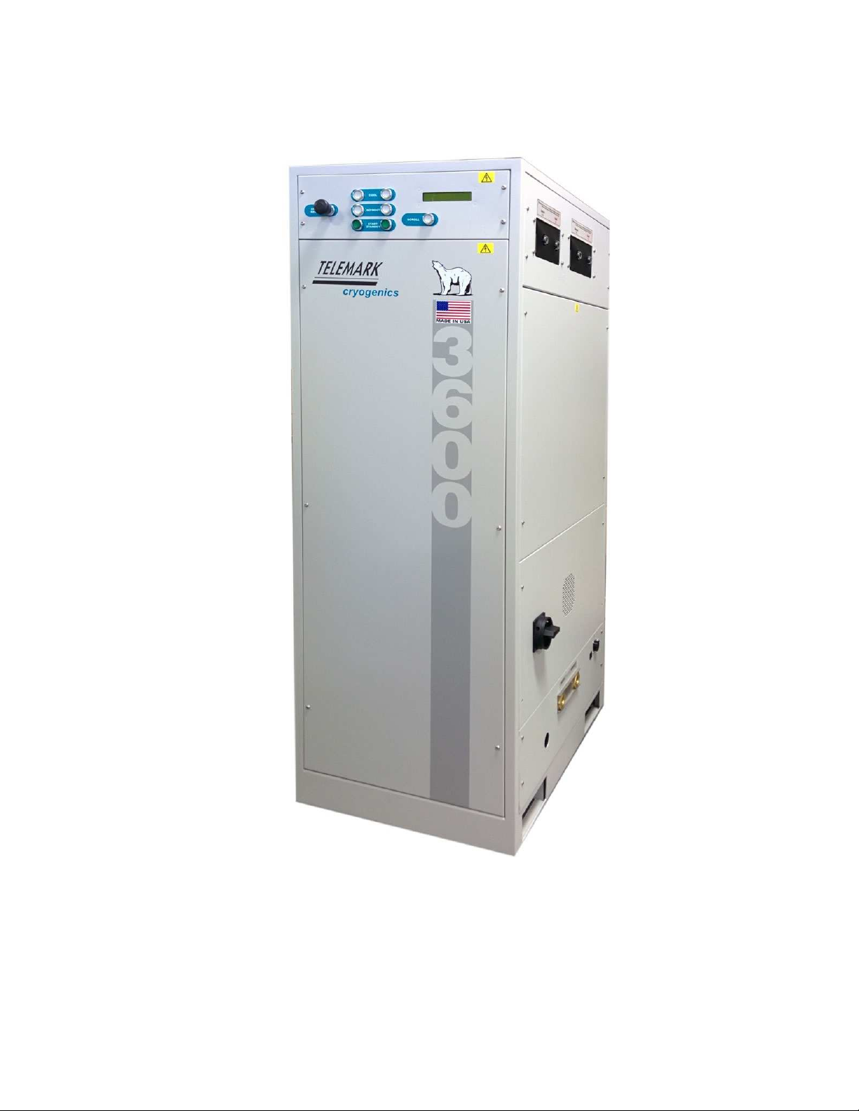
Model 3600 Water Vapor Cryo-Chiller
(Dual Coil Unit)

Telemark Cryogenics Microprocessor Based Cryochillers
Page 3of 63
Revision 1.0.7 October 2018
TABLE OF CONTENTS
Page
Table of Contents 3
Safety Warnings 7
Warranty 10
User Responsibility Intended Use of Equipment 11
Manufacturing Standards 11
1
Specifications
Models 1200, 1800 and 1800EXT 12
Models 2400, 3000 and 3600 13
1.1 Environmental Requirements 14
1.2 Recommended Breaker and Wire size 14
1.3 Physical Dimensions 15
2
Installation
Cautionary Notes 16
2.0 Unpacking and Inspection 17
2.1 System Pressure 18
2.2 Location 19
2.3 Panel removal 19
2.4 Water Connections 20
2.5 Refrigerant Line Connection 21
2.5.1 Metal O Seals 22
2.5.2 Using Gauge Manifolds 22
2.5.3 Access Valve 22
2.5.4 Connections 23
2.5.5 Evacuate Refrigerant Lines 23
2.5.6 Sealing Refrigerant Lines 23
2.5.7 Refitting Valve Access Cover 23
2.5.8 Refrigerant Line Notes 24
2.6 Electrical Connections 26
2.6.1 Main Power Connection 26
2.6.2 Cable Entry Point 26
2.6.3 Terminal Torque Requirements 26
2.6.4 Transformer Taping 27
2.7 Remote Connections 28
2.7.1 Digital Remote Control 29
2.7.1.2 Analogue Outputs 31

Telemark Cryogenics Microprocessor Based Cryochillers
Page 4of 63
Revision 1.0.7 October 2018
2.8 Ethernet Communications 32
2.8.1 Ethernet Setup 33
2.8.2 Serial Commands Available 35
2.8.3 Using TCP/IP GUI 36
2.8.4 User Configuration 39
3
Operation
3.0 Controls and Display 42
3.0.1 LCD Display 42
3.0.2 Scroll Push Button 44
3.0.3 Cool Push Button 44
3.0.4 Defrost Push Button 44
3.0.5 Standby Push Button 44
3.0.6 ON/OFF Puss Button 45
3.1 Operation 45
3.1.0 Main Isolator 45
3.1.1 Turning On the Unit 45
3.1.2 Standby 45
3.1.3 Cool 45
3.1.4 Defrost 45
3.1.5 Defrost Recovery Period 46
3.2 Normal Operating Ranges 46
4
Trouble Shooting Guide
4.0 Refrigeration Leaks 47
4.1 Alarm Codes/Messages 47
4.2 Safety Systems 48
4.2.1 Hardware Safety systems 48
4.3 Trouble Shooting Guide 50
4.4 Use of Top-off Charges 53
4.5 Emerson Compressor trouble
Shooting guide 53
4.5.1 Emerson Diagnostics 55
5
Decommissioning 58
6
Design of Cryo-coils 59
7
Chinese Hazardous Substance Concentration Table 63

Telemark Cryogenics Microprocessor Based Cryochillers
Page 5of 63
Revision 1.0.7 October 2018
LIST OF FIGURES/ILLUSTRATIONS
Figures Page
1 Removing Unit from Transport Pallet 18
2 System Pressure Gauge 18
3 Services Panel 19
4 Water Flow requirements 20
5 Position of Hand Valves 21
6 Refrigerant Line Connections 21
7 Access Hand Valve 22
8 Refrigerant Manifold 22
9 Refrigerant Line Insulation 24
10 Metal “O” Ring Removal Tool 25
11 Main Isolator Wiring 26
12 Transformer Tapings 27
13 37 Way Amp Connector 30
14 Ethernet cable (crossed) 32
15 Network Connection Window 33
16 Network Properties 33
17 TCP/IP 34
18 TCP/IP Settings 34
19 TCP/IP GUI 36
20 Ethernet TCP/IP & RS232/485 Help 38
21 “cal2309” Setup Screen 39
22 Front Panel Push Buttons 42
23 Wait Start LCD Display 42
24 Pre-Cool LCD Display 43
25 Standby LCD Display 43
26 Cool LCD Display 43
27 Over Pressure Alarm LCD Display 48
28 DP High LCD Display 48
29 Emerson Compressor Front Panel 54
30 Emerson Compressor Internal Parts 54

Telemark Cryogenics Microprocessor Based Cryochillers
Page 6of 63
Revision 1.0.7 October 2018
LIST OF TABLES/INFORMATION
Table Page
1 Model 1200. 1800 & 1800 EXT Specifications 12
2 Model 2400, 3000 & 3600 Specifications 13
3 Environmental Operating Conditions 14
4 Recommended Breaker and Wire Size 14
5 Physical Dimensions 15
6 Recommended Breaker and Wire Size 27
7 37 Way Connector Pin Connection Details 29
8 Volt vs. Temperature Conversion 31
9 Serial Communication read/write Commands 35
10 Display Mnemonics and their Meaning 43
11 Normal Operating range Parameters 46
12 Alarms and Error Codes 48
13 Trouble Shooting Guide 50
14 Trouble Shooting Guide – Emerson compressor 56
15 Maximum Recommended Coil Surfaces 60
T
WARNING
1)
The sy
signific
(a)
(b)
(c)
(d)
(e)
WARNING
The system
both a fros
known asp
taken and
personnel
WARNING
Removal o
operator to
electrocuti
THE P
PROBA
THE P
DUTY
THE E
THE O
BE SO
Telemark Cryogenics
Microprocessor Based Cr
Page
7
of
63
Revision
SAFETY WARNI
system contains specific hazards, which
ificant danger to personal safety;
High voltage electrical components and
hi
refrigerant gases, which are a significa
hazard.
R
efrigerant gases, which will cause asph
confined areas.
R
efrigerant gases, which if exposed
temperatures decompose to form very
products – never smok
e in the vicinity o
any other similar system including the gas
W
ater in close proximity to high voltage ele
Hot and cold surface
s which represent a
burn / frostbite hazard.
tem contains
gases under pressure, which ma
rostbite hazard and a burn hazard. Refrigerant
sphyxiates and are mildly narcotic. Precautio
d work must only be carried out by suitably qu
el
.
l of any panels other than the front door will ex
r to high voltage components, which may resu
ution.
PHRASE WARNING IS USED WHERE THER
BABILITY OF PERSONAL INJURY OR DEA
PROVISIONS HIGHLIGHTED BE IGNORED.
Y OF BOTH THE INSTALLER/OWNER AND OP
EQUIPMENT TO BE FAMILIAR AND COM
P
OPERATION AND USES OF THE PRODUCT
OUGHT FROM THE MANUFACTURER.
Cryochillers
ion 1.0.7 October 2018
NING
S
ch present a
high
-pressure
icant frostbite
sphyxiation in
ed to high
ery toxic by
-
y of a
UNIT or
gas cylinders.
electricity.
t a significant
ay constitute
nt gases are
tions must be
qualified
l expose the
sult in a fatal
ERE IS A HIGH
EATH SHOULD
D. IT IS THE
OPERATOR OF
PETENT WITH
CT. HELP MAY

T
WARNING
During ins
voltage co
electrocuti
WARNING
U
nits mus
Failure to c
with or rem
machine.
WARNING
Isolate sys
used is co
within the
three powe
Feed cable
having firs
primary gr
WARNING
Failure to r
fatal electr
be in place
WARNING
Always iso
attaching t
additional
WARNING
Failure to l
catastroph
risk from f
shutdown
guidance.
WARNING
The r
refriger
health
precau
a)
A
A
Telemark Cryogenics
Microprocessor Based Cr
Page
8
of
63
Revision
nstallation there is the potential to be exposed
components (up to
400v ac), which may result
ution.
ust always be operated with a suitable ground/
to comply may result in fatal electrocution. Nev
remove any ground/earth connection from insi
ystem before connection. Ensure the connect
compliant with local electrical requirements. C
e unit is tri
-
rated to CSA/UL/CE norms. There
wer wires and one ground wire; there is no ne
ble through gland and terminate at main syste
irst removed the protective cover. Ground the
ground point.
to replace
isolator cover exposes operators to
ctrocution. It is essential this primary protecti
ce before the system is energised.
isolate the system through the main circuit bre
g the
remote control. When in remote operatio
al care to prevent personal injury.
to leak test the system as a whole, may result i
phic release of refrigerant, which presents a v
frostbite and or
asphyxiation. See emergenc
n procedures and material safety data sheet f
e.
refrigeration system contains a mixed
gerants and polio
-
ester oil. These do not pr
th risks, but it is essential
that the follo
autions are followed:
A
lways wear eye protection.
A
lways wear surgical type rubber or latex glo
Cryochillers
ion 1.0.7 October 2018
ed to high
ult in a fatal
d/earth line.
ever tamper
side of
the
ction cable
. Cabling
re
must be
neutral line.
tem isolator,
the
UNIT at
to potentially
ction always
breaker before
tion take
lt in the
very high
ncy
t for
ed blend of
present acute
llowing basic
loves.

T
CAUTION
CAUTION
Telemark w
consequent
misuse of th
CAUTION
If the equip
manufactur
by impaired
CAUTION
It is the resp
county, stat
related to s
each install
equipment
CAUTION
-
HOT SU
High tempe
Avoid conta
during norm
CAUTION
-
COLD S
Freeze Burn
normal ope
CAUTION
-
PRESUR
Unit contain
system is c
for leaks. D
their design
manufactur
CAUTION
-
HAND V
Closure of t
temperature
systems wa
cryogenical
is causing g
lines.
The ph
produc
provis
Telemark Cryogenics
Microprocessor Based Cr
Page
9
of
63
Revision
will not be responsible or liable for either dire
ential personal injury or loss claims arising fro
f the product.
ipment is used in a
manner not specified by th
turer, the protection provided by the equipmen
red
esponsibility of the user to make sure all local,
tate and national codes, regulations, rules and
safety
and safe operating conditions are mee
allation. The safety of any system incorporatin
nt is the responsibility of the assembler of the
URFACE
peratures are generated during normal operati
ntact with exposed pipe
-
work as this can get h
rmal operation.
SURFACE
urn Risk. Very low temperatures generated du
peration. Avoid contact with exposed pipe
-
wo
URISED GAS
ains pressurised gas. Do not open hand valve
connected to a Cryo
-
coil, which has been che
. Do not connect the system to other systems
ign and application has been approved by the
turer
VALVES
f the hand valves while the system is at cryog
ures may damage the valve seats and invalida
warranty. It must only be attempted on a
cally cold system in the case of an emergency,
g gross leakage f
rom the Cryo-
coil or refrigera
phrase
“
Caution
”
indicates a risk of damage t
uct or
associated plant and machinery if the
isions are not followed
carefully.
Cryochillers
ion 1.0.7 October 2018
irect or
from the
the
ent may
al,
nd laws
eet for
ting the
e system.
ation.
t hot
during
work
.
lves until
hecked
s unless
e
ogenic
date the
cy, which
rant
e to the

Telemark Cryogenics Microprocessor Based Cryochillers
Page 10 of 63
Revision 1.0.7 October 2018
WARRANTY
Telemark Cryogenics Cryochiller products are warranted to be free from
defects in materials and/or workmanship under normal usage until warranty
effective date listed on serial number label. Telemark Cryogenics’ obligation
under this Warranty is limited to the repair or replacement, at its option, of any
parts, which upon examination at the Telemark Cryogenics factory or by an
authorised sales/service representative, shall appear to have become
defective. Correction of defects by repair or replacement shall be either at the
Telemark factory or in-situ by an authorised service representative. The
location of repair shall be at the discretion of Telemark Cryogenics. Repairs
carried out at Telemark Cryogenics factory shall be FOB Telemark factory
and shall constitute fulfilment of obligations to the purchaser. All
transportation costs for defective parts or products shall be borne by the
purchaser. Telemark Cryogenics will not be liable for loss, damage, or other
expenses directly or indirectly arising from the use of its products or from any
other causes. Telemark assumes no liability for expenses or repairs made
outside of its factory by non-authorised personnel.
All claims on account of defective material or workmanship shall be deemed
waived unless made in writing within the aforementioned warranty period.
The foregoing Warranty is in lieu of all other warranties expressed or implied.
Telemark neither assumes nor authorises any other person to assume any
other obligation or liabilities in conjunction with the sale of its products. This
Warranty shall be void if the equipment has been subject to misuse,
negligence or application outside of recommended operating environment or
conditions. The Warranty will also be invalidated if the identification numbers
of the system have been altered, defaced or removed.
The Warranty is not intended to supplant any statutory rights the purchaser
may have.
Unit start and end dates are printed on the unit’s serial number label.
USER RESPONSIBILITY
The user is responsible for proper installation, operation and ordinary
maintenance of the equipment following the procedures in this manual. The
warranty may be void if the equipment is improperly installed. Alteration of
the design and or any function of the equipment voids the warranty and is
entirely the responsibility of the user.
Telemark will not be held responsible or liable for either director
consequential personal injury or loss claims arising from the misuse of the
product
The user should read this manual in its entirety before carrying out any
work and or operation of a Telemark Cryochiller.

Telemark Cryogenics Microprocessor Based Cryochillers
Page 11 of 63
Revision 1.0.7 October 2018
INTENDED USE OF THE
EQUIPMENT
Water vapor Cryochiller is a device that improves the performance of vacuum
pumping due to the efficient trapping of water vapor in the chamber.
Classically a Cryochiller is used with an evaporative surface (Meissner/cryo-
coil), which is located within the vacuum chamber. When in this configuration
a Telemark Cryochiller is an ultrahigh performance vacuum pump capable of
pumping water vapor and other condensable gases at speeds far in excess of
conventional vacuum pumps.
A Telemark Cryochiller couples speed with a sophisticated computer control
package which includes a simple and adaptable user interface with isolated
inputs/outputs and Ethernet comms package as standard. RS232 and RS485
serial communication options are available.
The ranges of tasks to which your Cryochiller can be applied are not limited to
pumping water vapor in vacuum. Many are used as substrate coolers (chuck
coolers) or other applications where a continuous level of high power cooling
in the range –100 to –150
o
c is required.
STANDARDS
The device is compatible in terms of electromagnetic compatibility and safety
standards. Applicable standards:
EMC: DIRECTIVE 2014/30/UE - STANDARD EN 61326-1:2013
LVD: DIRECTIVE 2014/35/EU - STANDARD EN 61010-1:2011
And applicable causes of the standard: EN 378-2:2008

Telemark Cryogenics Microprocessor Based Cryochillers
Page 12 of 63
Revision 1.0.7 October 2018
1
SPECIFICATIONS
Model
1200
Model
1800
Model
1800EXT
Maximum Load (Watts) 1,200 1,800 1,800
Typical
Pumping Speed (l/sec) 65,000 100,000 100,000
Ultimate Vacuum 2 x10
-
8
mbar (2 x10
-
6
Pa) 2 x10
-
8
mbar (2 x10
-
6
Pa) 2 x10
-
8
mbar (2 x10
-
6
Pa)
Weight (Kg) 193 (432 lbs) 243 (536 lbs) 243 (536 lbs)
Size inch (mm)
L
W
H
24 (559)
22 (610)
59.5 (1511)
24 (559)
22 (610)
59.5 (1511)
24 (559)
22 (610)
59.5 (1511)
Power supply
380-444VAC 3 ph 50Hz
460VAC 3 ph 60 Hz
200-230VAC 3 Ph 50/60 Hz
380-444VAC 3 ph 50Hz
460VAC 3 ph 60 Hz
200-230VAC 3 Ph 50/60 Hz
380-444VAC 3 ph 50Hz
460VAC 3 ph 60 Hz
200-230VAC 3 Ph 50/60 Hz
Wire/Cable Connection 3 Phase + Ground (Earth) 3 Phase + Ground (Earth) 3 Phase + Ground (Earth)
Full Load Current draw @
60 Hz (Amps)
@200-230VAC
@380-440VAC
20
10
30
15
30
15
Start Up Max
Current Draw @ 60 Hz
(Amps)
@200-230VAC
@380-440
30
15
60
30
60
30
Compressor Horsepower
(HP) 4.5 (3.35kW) 7.5 (5.59Kw) 7.5 (5.59kW)
Water Requirements
(l/min)
@ 15°C
@ 25°C
@ 32°C
5
10
20
5
10
20
5
10
20
Water Connections All Models ¾” NPT Female
Water Resistivity All Models >0.1MChloride Free
Water Ph All Models 6.5 - 8
Refrigeration Connections ½” Metal Seal ½” Metal Seal ½” Metal Seal
Max Coil Length (Meters)
Using ½” Cu tube 20 (65.6 ft) 25 (82 ft) 25 (82 ft)
Max Surface area (M
2
) 0.79 (≈8.57 ft
2
) 0.99 (≈10.72 ft
2
) 0.99 (≈10.72 ft
2
)
*Avg. Cool Time (mins) 2-5 2-5 2-5
*Avg. Defrost Time (mins) 2-4 2-4 2-4
∆T Coil in/Coil Out (°C) ≈5 ≈5 ≈5
Digital Remote
Connections
Input Voltage range
18-24VDC (30VDC MAX) 18-24VDC (30VDC MAX) 18-24VDC (30VDC MAX)
Digital Remote
Connections
Output Voltage range
Relay contact closure 200
VAC or 100VDC Max at
300mA
Relay contact closure 200
VAC or 100VDC Max at
300mA
Relay contact closure 200
VAC or 100VDC Max at
300mA
Balance Pressure Range
as Shipped from Telemark
USA facility
(PSI) @20°C
(hand valves closed)
270-300
(1.86-2.07MPa)
220-250
(1.51-1.72MPa)
180-210
(1.24-1.45MPa)
Table 1 Model 1200, 1800, 1800EXT Specifications

Telemark Cryogenics Microprocessor Based Cryochillers
Page
13
of
63
Revision 1.0.7 October 2018
Model
2400
Model
3000
Model
3600
Maximum Load (Watts) 2400 3000 3,600
Typical
Pumping Speed (l/sec) 135,000 165,000 200,000
Ultimate Vacuum 2 x10
-
8
mbar (2 x10
-
6
Pa) 2 x10
-
8
mbar (2 x10
-
6
Pa) 2 x10
-
8
mbar (2 x10
-
6
Pa)
Weight (Kg) 243 (485 lbs) 384 (845 lbs) 412 (930 lbs)
Size inch (mm)
L
W
H
24 (559)
22 (610)
59.5 (1511)
35.3 (897)
23.6 (897)
70.25 (1784)
35.3 (897)
23.6 (897)
70.25 (1784)
Power supply
380-444VAC 3 ph 50Hz
460VAC 3 ph 60 Hz
200-230VAC 3 Ph 50/60 Hz
380-444VAC 3 ph 50Hz
460VAC 3 ph 60 Hz
200-230VAC 3 Ph 50/60 Hz
380-444VAC 3 ph 50Hz
460VAC 3 ph 60 Hz
200-230VAC 3 Ph 50/60 Hz
Wire/Cable Connection 3 Phase + Ground (Earth) 3 Phase + Ground (Earth) 3 Phase + Ground (Earth)
Full Load Current draw @
60 Hz (Amps)
@200-230VAC
@380-440VAC
40
20
50
25
60
30
Start Up Max
Current Draw @ 60 Hz
(Amps)
@200-230VAC
@380-440
60
30
60
30
85
45
Compressor Horsepower
(HP) 10 (7.46kW) 13 (9.69kW) 15 (11.19kW)
Water Requirements (l/min)
@ 15°C
@ 25°C
@ 32°C
6
12
30
6
12
30
8
16
30
Water Connections ¾” NPT Female
Water Resistivity All Models >0.1MChloride Free
Water (Ph) All Models 6.5 - 8
Refrigeration Connections ½” Metal Seal ½” Metal Seal ½” Metal Seal
Max Coil Length (Meters)
Using ½” Cu tube 35 (114.8 ft) 40 (131.2 ft) 50 (164.0 ft)
Max Surface area (M
2
) 1.39 (≈15 ft
2
) 1.59 (≈17.1 ft
2
) 1.99 (≈21.42 ft
2
)
*Avg. Cool Time (mins) 2-5 2-5 2-5
*Avg. Defrost Time (mins) 2-4 2-4 2-4
∆T Coil in/Coil Out (°C) ≈5 ≈5 ≈5
Digital Remote
Connections
Input Voltage range
18-24VDC (30VDC MAX) 18-24VDC (30VDC MAX) 18-24VDC (30VDC MAX)
Digital Remote
Connections
Out Voltage range
Relay contact closure 200
VAC or 100VDC Max at
300mA
Relay contact closure 200
VAC or 100VDC Max at
300mA
Relay contact closure 200
VAC or 100VDC Max at
300mA
Balance Pressure Range
as shipped from Telemark
USA facility
(PSI) @20°C
(hand valves closed)
190-220
(1.31-1.52MPa)
250-280
(1.72-1.93MPa)
250-280
(1.72-1.93MPa)
IMPORTANT
.
The above performance figures are based for a unit
running at 60Hz mains power frequency. For units running on 50 Hz
mains frequency the figures above need to be de-rated by 0.83.
Table 2 Model 2400, 3000, 3600 Specifications
Telemark Cryogenics Microprocessor Based Cryochillers
Page 14 of 63
Revision 1.0.7 October 2018
1.1 Environmental conditions (all models)
Parameter Value
Type Indoor use
Altitude
Up to 2000m
Temperature range (°C) 5 - 40
Humidity (%Rh) Maximum relative 80% for temperatures up to 31
⁰
C
decreasing linearly to 50% relative humidity at 40
⁰
C
Mains supply voltage
fluctuations
Up to 10% of the nominal voltage
Pollution degree 2
Overvoltage category
II
Table 3 Environmental Conditions
1.2 Croychiller - recommended circuit breaker Values and Wire Size
200-230VAC Vac Three-Phase
Nominal current
rating[A]
Fuse
Rating [A]
Minimum copper
wire
AWG/mm
2
Cable Type
(recommended)
30 70 8 / 10 H07RN-F 450/750V 4G10
50 100 6 / 16 H07RN-F 450/750V 4G16
60 125 4 / 25 H07RN-F 450/750V 4G25
380-444VAC Three-Phase
15 30 14 / 2.5 H07RN-F 450/750V 4G2.5
25 45 10 / 6 H07RN-F 450/750V 4G6
30 60 10 / 6 H07RN-F 450/750V 4G6
Table 4 Recommended Breaker and Wire Size
Telemark Cryogenics Microprocessor Based Cryochillers
Page
15
of
63
Revision 1.0.7 October 2018
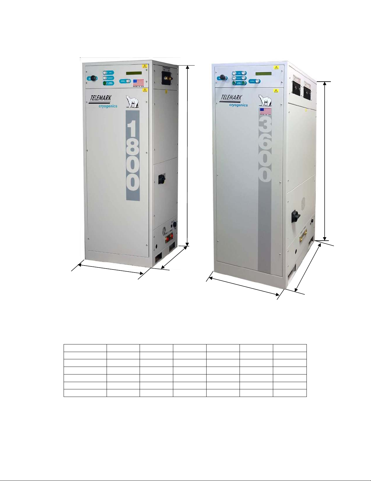
1.3 Cryochiller Physical Dimensions
Model A (inch) A (mm) B (inch) B (mm) C (inch) C (mm)
1200 22 559 24 610 59.5 1511
1800 22 559 24 610 59.5 1511
1800EXT 22 559 24 610 59.5 1511
2400 22 559 24 610 59.5 1511
3000 23.6 599 35.3 897 70.25 1784
3600 23.6 599 35.3 897 70.25 1784
A
A
B
B
C
C
Table 5 Physical Dimensions

T
Safety and
Caution
WARNING
Failing to leak
catastrophic r
from frostbite
procedure an
WARNING
The system
u
components.
always isolate
system. A qu
connections
,
WARNING
The system c
both a frostbit
known
asphy
taken. Work
Always wear
WARNING
All refrigeratio
manipulated m
laws require i
certification o
countries mig
regulations sh
be paid to con
Telemark Cryogenics
Microprocessor Based Cr
Page
16
of
63
Revision
INSTALLAT
onary Notes for Installation.
ak test the system as a whole may result in the
ic release of refrigerant, which presents a very hig
ite and/or asphyxiation. See emergency shut
dow
and
material safety data sheet.
uses
high voltage (208 or 415VAC) and high pow
ts. To avoid the possibility of a fatal electrical sho
late the unit from the mains supply before working
qualified technician, as for all high power electrica
, should carry out the electrical work
contains gases under pressure, which may cons
tbite hazard and a burn hazard. Refrigerant gases
hyxiates
and are mildly narcotic. Precautions mus
rk must only be carried out by suitably qualified pe
ar suitable eye and protection
ation work in which the refrigerant gas is moved or
d must be
done by a qualified technician. Many n
e individuals who perform such work must have a
of Refrigeration Technician. Other laws in variou
ight govern use or service of this system. Local
should be s
trictly adhered to. Particular attention
containment and recovery of refrigerants.
Cryochillers
ion 1.0.7 October 2018
2
ATION
high risk
own
power
hock
ng on the
ical
nstitute
ses are
ust be
personnel.
or
y national
a
ious
al
ion should
T
WARNING-
TIP OVER RI
Use proper
from the pa
WARNING –
HEAVY OBJ
Telemark
to 412Kg (9
result in inj
CAUTION
–
PRESU
Unit contain
system is co
leaks. Do n
design and
and t
hey ha
CAUTION
–
ENVIRO
Do not relea
dangerous;
regarding th
Safety Data
to your loca
2.0
Unpacking and Inspe
Before unpacking the
condition.
The case is reusable a
respect. When remov
containing the
refriger
components are not
d
2.1 The unit
is mounted to
on which the unit is
No
or
the
Telemark Cryogenics
Microprocessor Based Cr
Page
17
of
63
Revision
RISK
per lifting equipment and protocols when removing
pallet
BJECT RISK
Cryochillers weigh a minimum of 193Kg (432
lb)
g (930lb). Failure to follow correct lifting practices
injury or death
SURISED GAS
ains pressurised gas. Do not open hand valves un
connected to a Cryo
-
coil, which has been checke
o not connect the system to other systems unless
d application has been approved by the manufac
have been assessed fro leak tightness
IROMENTAL RISK
lease refrigerant into the atmosphere it is illegal an
s; please refer to your local authorities instruction
the disposal of reclaimed refrigerants.
Read the
ta Sheet before installing the system. Verify com
cal
regulations.
spection
he unit please verify that the packaging is in good
le and recyclable. Please treat the environment w
oving the unit from the case ensure that any bags
eration line connections, tool kit and other essent
discarded.
to the pallet with four
packing bolts
. The woode
is shipped must be removed prior to installatio
Note:
The unit must only be moved either by forkl
or strapping through the fork lift truc
k points locate
the side of the unit.
Cryochillers
ion 1.0.7 October 2018
ing the unit
lb) and up
es may
until
ked for
ss their
acturer,
l and
ons
he Material
mpliance
od
t with
gs/boxes
ential
den
pallet
tion
.
rklift truck
ated to
Telemark Cryogenics Microprocessor Based Cryochillers
Page
18
of
63
Revision 1.0.7 October 2018
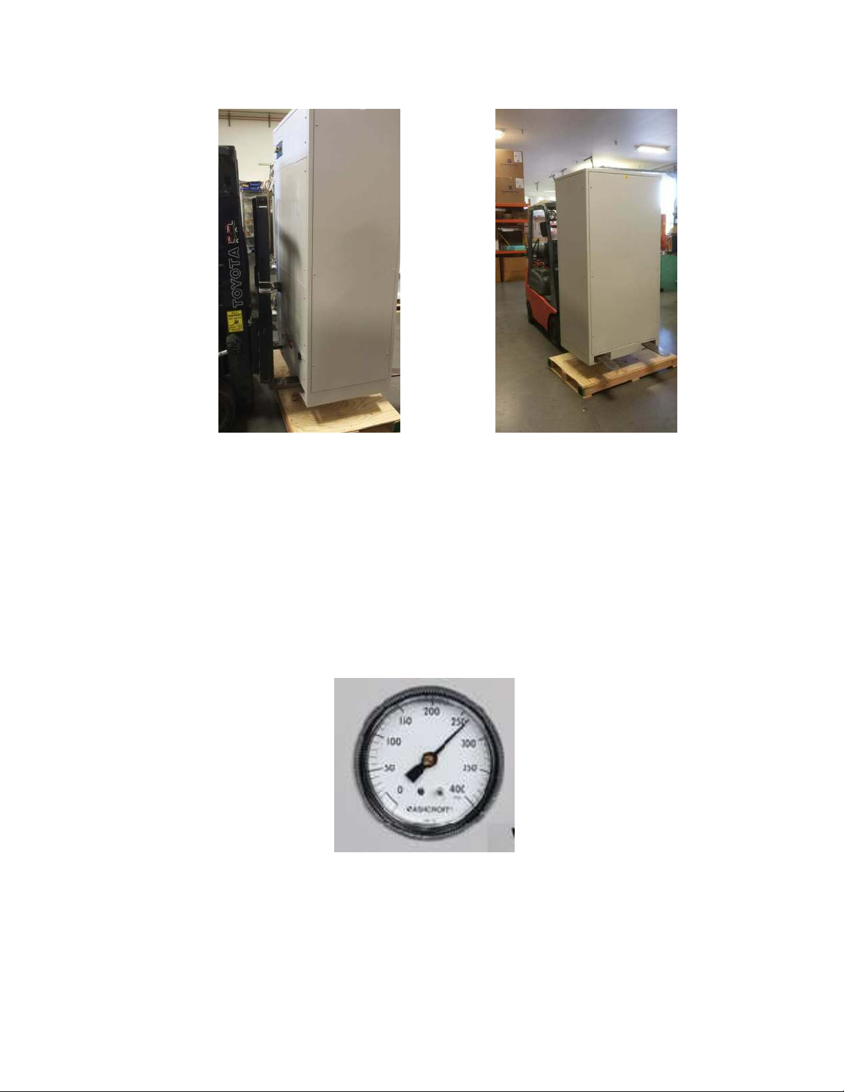
2.2 System Pressure
The unit is shipped fully charged. See Tables 1 and 2 (Section 1
“Specifications”) above for shipping pressure range of each model. The exact
shipping pressure is noted on the packing list. A pressure gauge is mounted
behind the front panel or to the right hand side of the unit. The static pressure
may vary by up to +/- 16 psi due to changes in the ambient temperature.
Fig 1 Removing Unit from transportation pallet
Fig 2 Pressure gauge
Telemark Cryogenics Microprocessor Based Cryochillers
Page
19
of
63
Revision 1.0.7 October 2018
2.3 Location
The unit should be placed and a clean level floor and positioned to minimise
the length of the refrigeration lines. It is also important that the lines are well
supported and are manufactured from annealed copper tubing allowing for
thermal expansion and vibration. The units should be placed at least 3”
(80mm) away from the nearest obstructions to allow for sufficient air flow to
the unit.
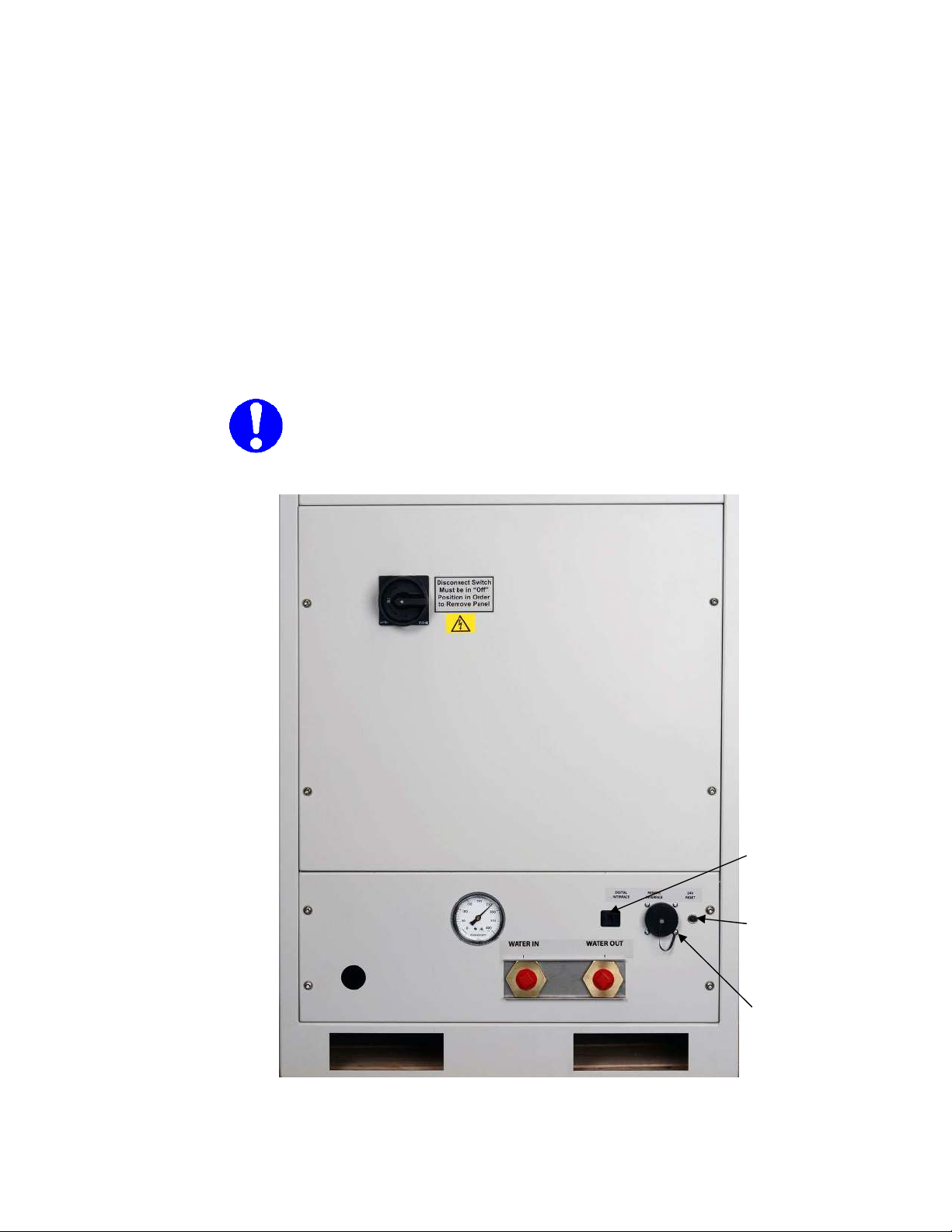
2.4 Panel Removal.
Remove the front panel to gain access to “hand valve” gas box. Remove the
6 (or 8 screws depending upon model) and remove the front panel exposing
the hand valves. Remove the right hand side panel where the isolator handle
is located.
Note: the panel can only be removed with the isolator
switch in the “OFF” position
Fig 3 Services Panel
Remote
Interface
Connector
Power Cable Entry
Point
Main
Power
Isolator
Digital Interface
Port (Ethernet)
Balance/Suction
Pressure Gauge
24 VDC Circuit
Breaker

Telemark Cryogenics Microprocessor Based Cryochillers
Page
20
of
63
Revision 1.0.7 October 2018
2.5 Water Connections
The advanced design of the unit means it is capable of operating over a
wide range of water temperatures. While Liquid Line temperature (LT on the
display) is preset to 40°C maximum, there is littl e loss of performance with
water (outlet – this is not displayed on the unit) temperatures as high as 35
°
C.
Higher water temperatures result in a slight loss of capacity while water colder
than 15°C will slow the systems response and lead to undue condensation on
water lines.
In-house re-circulating water-cooling system is required. Water must be free
from chlorides and sufficiently soft to prevent the build up of lime scale (0.1
M
resistivity). Ensure that the water is clean and free from any clogging
debris. The Ph value should be between 6.5 and 8. The water inlet and
outlet pipe-work needs to have a minimum diameter of ¾ inch (15mm). The
use of a suitable biocide can be beneficial when used in closed loop water
systems.
Connect the water lines to the unit ensuring the correct orientation of the
water lines (see fig 3 above). Turn on water flow and ensure no leakage is
present at connectors. Open the cabinet and check visually for water
leaks inside the cabinet.
Water temperature below ambient temperature, may cause condensation.
Additional insulation of the internal water lines may be required if the cooling
water temperature is low and the ambient humidity is high.
The graph (fig 4) below indicates the cooling water flow required at varying
inlet temperatures. As a practical limit, a flow rate of 30 l/min is
approximately equivalent to a 15psi (1bar) pressure drop across the Unit.
0
5
10
15
20
25
30
35
10 15 20 25 30 35 40
Water Flow (l/min)
Water Temperature (C)
3600
3000, 2400
1200,1800 1800EXT
Fig 4, Water flow Requirements
This manual suits for next models
5
Table of contents
Other Telemark Cryogenics Laboratory Equipment manuals


