Quanser Shake Table II User manual

Solutions for teaching and research. Made in Canada.
USER MANUAL
Shake Table II
Set Up and Configuration
CAPTIVATE. MOTIVATE. GRADUATE.

© 2017 Quanser Inc., All rights reserved.
Quanser Inc.
119 Spy Court
Markham, Ontario
L3R 5H6
Canada
info@quanser.com
Phone: +1-905-940-3575
Fax: +1-905-940-3576
Printed in Markham, Ontario.
For more information on the solutions Quanser Inc. offers, please visit the web site at:
http://www.quanser.com
This document and the software described in it are provided subject to a license agreement. Neither the software nor this document may be
used or copied except as specified under the terms of that license agreement. All rights are reserved and no part may be reproduced, stored in
a retrieval system or transmitted in any form or by any means, electronic, mechanical, photocopying, recording, or otherwise, without the prior
written permission of Quanser Inc.
STII User Manual 2

CONTENTS
1 Presentation 4
2 Components 6
2.1 Nomenclature 6
2.2 Description 6
3 Specifications 9
4 System Setup 10
4.1 Cable Nomenclature 10
4.2 Connections 11
4.3 Mounting the Shake Table II 13
5 Maintenance 16
6 X-Y Shake Table II Configuration 17
6.1 Mounting the Shake Tables 17
6.2 Cable Connections 19
7 Troubleshooting 21
8 Technical Support 22
STII User Manual v 3.1

1 PRESENTATION
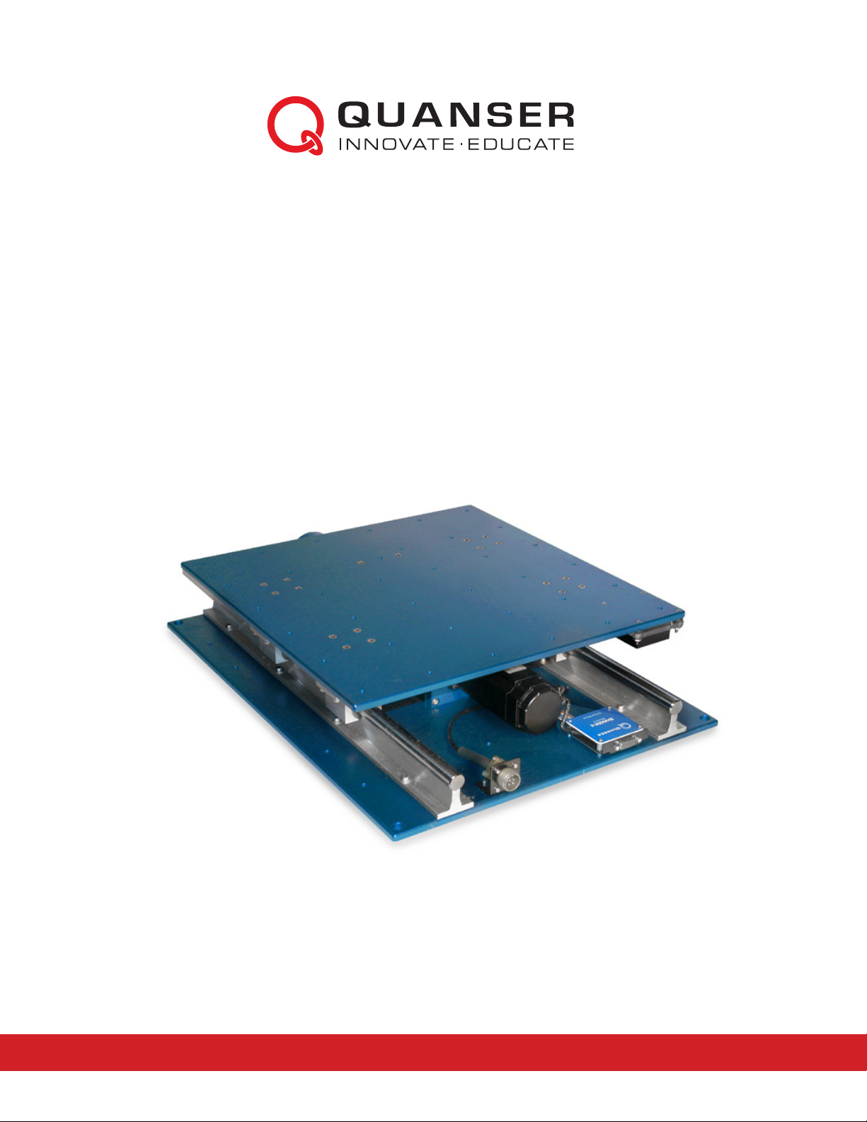
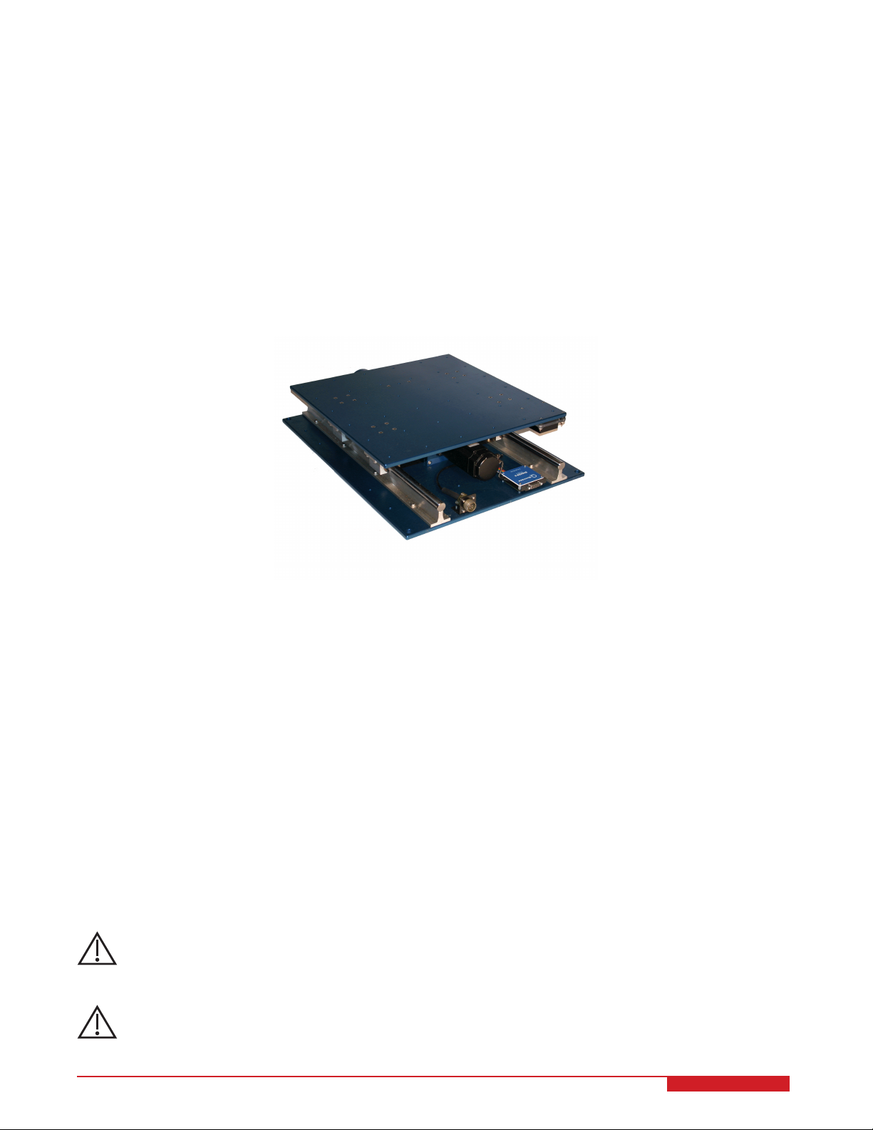
The Quanser Shake Table II (STII) shown in Figure 1.1 is an instructional shake table device that was originally
developed for the University Consortium on Instructional Shake Tables (UCIST). It can be used to teach structural
dynamics, vibration isolation, feedback control, and various other topics for mechanical, aerospace, and civil engi-
neers.
The shake table is rated to drive a 7.5 kg load at 2.5 g. The stage rides on two ground-hardened metal shafts
using linear bearings which allows for smooth linear motions with low path deflection. When starting from center the
stage is capable of moving ±7.62 cm, or ±3-inches (i.e., total travel of 15.24 cm). The 400 Watt 3-phase brushless
DC actuator is connected to a robust ball-screw assembly. The motor has an embedded high-resolution encoder
used to measure stage position with a resolution of 3.10 µm. An analog accelerometer is mounted to measure the
acceleration of the stage directly.
Figure 1.1: Quanser Shake Table II
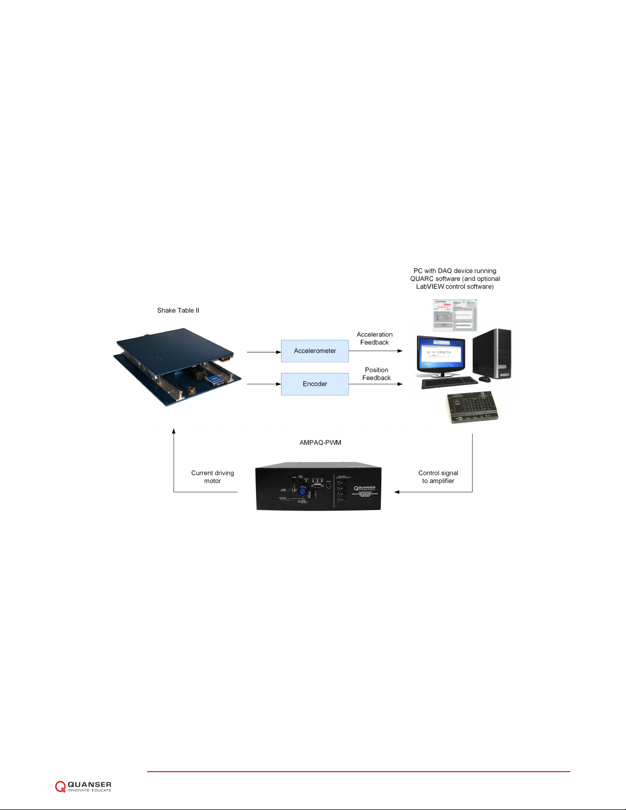
The main devices used to run the shake table is depicted in Figure 1.2. The entire system is comprised of:
1. Quanser Shake Table II
2. Power amplifier: Quanser AMPAQ-PWM
3. Data acquisition (DAQ) device: Quanser Q2-USB, Q8-USB, or QPIDe.
4. PC running QUARCrsoftware (optional: LabVIEW™ -based STII Control Software)
The interaction between the different system components is shown in Figure 1.2. Using QUARCror the optional
LabVIEW™ -based Control Software on the PC/laptop, the user specifies a command signal to the shake table (e.g.,
sine wave, earthquake). The current needed to move the stage to the desired position is calculated in QUARCr
and sent through the analog output channel of the DAQ device to the power amplifier. The amplifier applies the
current and drives the motor on the Shake Table II. The table tracking the commanded signal and the resulting
displacement and acceleration of the stage are measured by the on-board encoder and the accelerometer sensors.
The encoder and accelerometer are connected to the DAQ and their signals can be displayed and processed further
in QUARCror the optional LabVIEW™ -based Control Software. Plotted data can be also be saved for later analysis.
Caution: This equipment is designed to be used for educational and research purposes and is not
intended for use by the general public. The user is responsible to ensure that the equipment
will be used by technically qualified personnel only.
Caution: The Shake Table II is very loud when in operation. Please use ear protection when working in close
proximity to the shake table, or isolate the shake table in a sound proof enclosure where available.
STII User Manual 4

Figure 1.2: Interaction between main Shake Table II components
STII User Manual v 3.1

2 COMPONENTS
The Shake Table II components are identified in Section 2. Some of the those components are then described in
Section 2.2.
Caution: Be careful of the moving parts that form the Shake Table II mechanical system.
2.1 Nomenclature
The components listed in Table 2.1 are labeled in Figure 2.1.
ID Component ID Component
1 Stage 9 Sensor circuit board
2 Base plate 10 Right limit sensor
3 DC motor 11 Home position sensor
4 Lead screw 12 Left limit sensor
5 Ball nut 13 Motor leads connector
6 Manual adjustment knob 14 Motor encoder and hall sensors connector (i.e. potentiometer)
7 Linear guide 15 Accelerometer
8 Linear bearing block 16 Accelerometer connectors
Table 2.1: Components
2.2 Description
2.2.1 Stage
The top stage on the Shake Table II is shown as ID #1 in Figure 2.1. It is 18 ×18 inch2, or 45.7 ×45.7 cm2, and 9.7
mm thick. The stage has many screw holes that can be used to mount structures and other objects, e.g., Quanser
Active Mass Damper.
2.2.2 Bottom Plate
The bottom support plate, shown in by ID #2 in Figure 2.1, is 24 ×18 inch2, or 60.9 ×45.7 cm2, and 1.24 mm
thick. The steel linear guides and ball-screw are installed onto this plate. There bottom plate has 4 large screw
holes at each corner and smaller screw holes along the sides of the plate. These can be used to fasten the shake
table onto a ground floor support to prevent the shake table system from moving, or at least reduce the amount of
vibration. Although this is not necessary, it is recommended in order to yield more precise results when, for instance,
measuring acceleration.
2.2.3 DC Motor
The Shake Table II incorporates a Kollmorgen AKM24 brushless 3-phase DC Motor, shown by ID #3 in Figure 2.1.
The motor has a power of 400 W. It is connected to a ball-screw that and drives the ball nut assembly fastened to the
bottom of the shake table platform. The brushless commutation is ensured through three hall sensors with a phasing
of 120 degrees. Some of the motor specifications are included in Table 3.1. More detailed motor specifications are
available in the motor specification sheet [2] under AKM24F.
STII User Manual 6

Caution: Input 15 A peak, 3.75 A continuous.
2.2.4 Lead Screw
The lead screw, shown by ID #4 in Figure 2.1, circulates through a ball nut, component #5 in Figure 2.1, that is
attached to the bottom of the shake table stage and is rotated by the motor. The lead screw has a pitch of 0.50
inches. Thus the shake table stage moves 0.50 inches, or 1.24 cm, per single ball-screw revolution.
Caution: Exposed moving parts.
2.2.5 Encoder
The encoder is embedded inside the DC motor and is used to measure the linear position of the stage. It cannot be
identified externally. The motor encoder has a resolution of 2048 lines per revolution. In quadrature mode this gives
8192 counts per full rotation motor shaft rotation. The effective resolution, i.e., minimum linear position that can be
detected, of the stage displacement is 3.10 µm.
2.2.6 Linear Bearing Block
For smooth motion, the stage is fitted with low friction linear ball bearing blocks, shown by ID #8 in Figure 2.1, that
glide on two ground hardened shafts, identified by component #7 in Figure 2.1.
2.2.7 Limit Switches
These Right,Home, and Left, proximity sensors are shown in Figure 2.1 with ID #10, 11, and 12, respectively.
The Left or Right limit switches get triggered when the top stage moves close to the left or right mechanical range.
Similarly, the Home sensor is set to high when the top stage is at the mid-stroke or center position. These sensors
are used to deactivate the power amplifier for safety as well as for calibrating the stage to its center position.
2.2.8 Accelerometer
A dual-axis ADXL325 accelerometer is mounted underneath the stage of the Shake Table II to measure the acceler-
ation of the stage in both the xand ydirections. It is shown with ID #15 label in Figure 2.1. The sensor has a range
of ±10 g and its noise, in the operating range of the shake table, is approximately ±5.0 mV, i.e., ±5.0 mg. The
analog sensor is calibrated such that 1 V equals 1 g, or 9.81 m/s2. See the ADXL325 accelerometer specification
sheet [1] for more details.
Caution: The accelerometer readings can be misleading and lead to unexpected results. Please use caution
when using them as they are generally used as indicators.
STII User Manual v 3.1

(a) Top View
(b) Top Corner View
Figure 2.1: Shake Table II Components
STII User Manual 8

3 SPECIFICATIONS
Table 3.1 lists and characterizes the main parameters associated with the Shake Table II.
Symbol Description Value
RmMotor armature resistance 2.94 Ω
LmMotor armature inductance 6.16 mH
ktMotor current-torque constant 0.36 N-m/A
kmMotor back-emf constant 0.224 V/(rad/s)
PbBall screw pitch 0.0127 m/rev [0.5in/rev]
Ml,max Maximum total load mass 15.0kg [33.0lb]
MsMass of Shake Table II system 27.2kg [60.0lb]
Dimension of top stage. 0.46 ×0.46 m2
[18 ×18 in2]
Dimension of bottom stage. 0.61 ×0.46 m2
[24 ×18 in2]
Height from bottom to top stage 12.4cm [4.875 in]
xmax Maximum stroke position from midway point. 76.2mm [3.0in]
vmax Maximum velocity of stage. 664.9mm/s
[26.18 in/s]
Fmax Maximum force of stage. 708.7N [159.3lb]
amax Maximum acceleration of stage for 0kg load. 24.5m/s2
gmax Maximum rated acceleration of stage for 0kg load. 2.50 g
K_ENC Encoder sensitivity gain 3.1006 µm/count
1.22 ×10⁻⁴in/count
K_ACC Accelerometer sensitivity gain −1g/V
Dynamic load capacity of ball nut. 12000 N [2697.6lb]
Life expectancy of ball nut at full load. 6.35 ×10⁸m
[2.50 ×10¹⁰ in]
Life expectancy of linear bearing. 6.35 ×10⁶m
[2.5×10⁸in]
Load carrying capacity of linear bearings. 131.5kg [290 lb]
Table 3.1: Specifications
STII User Manual v 3.1

4 SYSTEM SETUP
The following is a listing of the hardware components used in this experiment:
1. Power Amplifier: Quanser AMPAQ-PWM.
2. Data Acquisition Device: Quanser Q2-USB, Q8-USB, or QPIDe.
3. Shake table plant: Quanser Shake Table II.
See the corresponding documentation for more information on these components. The cables supplied with the
Shake Table II are described in Section Section 4.1 and the procedure to connect the above components is given
in Section 4.2.
Caution: If the equipment is used in a manner not specified by the manufacturer, the protection pro-
vided by the equipment may be impaired.
4.1 Cable Nomenclature
The cables used to connect the Shake Table II, AMPAQ-PWM, and DAQ are shown in 4.1. Depending on your
configuration, not all these cables are necessary.
Cable
No.
Cable Type Description
1
RCA Cable
2xRCA to 2xRCA RCA-to-RCA cables connect the AMPAQ-PWM
Amplifier Command,Current Sense,S1,S2,S3,
and S4 connectors to a DAQ.
2
Shake Table II Motor Cable
4-pin-Amphenol
to 4-socket-
Amphenol
The 3-phase motor cable connects the output of
the AMPAQ-PWM amplifier to the motor on the
Shake Table II system.
3
E-Stop and Calibration Switch
E-Stop and Cali-
bration Switch
The E-Stop and Calibration switch must be con-
nected to the AMPAQ-PWM for proper operation.
The E-Stop switch locks in the disabled position
when pressed and the Calibration switch must be
pressed during the calibration of the table. To re-
lease the E-Stop, twist the red button clockwise.
STII User Manual 10

Cable
No.
Cable Type Description
4
From Device Cable
DB15 to DB15 This cable connects the AMPAQ-PWM From De-
vice connector to the Shake Table II circuit board.
It carries the three limit switch signals, the motor
Hall effect signals, and the motor encoder sig-
nals. It also supplies the DC power required by
the sensors.
5
Encoder Cable
5-pin-stereo-DIN to
5-pin-stereo-DIN
This cable carries the encoder signals between
the AMPAQ-PWM Encoder connector and the
DAQ. These signals are: +5 VDC power supply,
ground, channel A, and channel B. (Channel Z is
optional.)
6
Analog Cable
6-pin-mini-DIN to
6-pin-mini-DIN
This cable connects an external analog sensor
to the AMPAQ-PWM S1,S2,S3, or S4 connec-
tor. The cable also supplies ±12 VDC from the
AMPAQ-PWM to power the sensor.
7
Digital I/O Cable
16-pin Ribbon Ca-
ble
This cable connects the Digital I/O connector on
the AMPAQ-PWM to a Q2-USB or QPIDe DAQ.
8
Split Digital I/O Cable
Split 16-pin Ribbon
Cable
This cable connects the Digital I/O connector on
the AMPAQ-PWM to a Q8-USB.
Table 4.1: Cables used to connect the AMPAQ-PWM to a Quanser DAQ and experiment
4.2 Connections
This section describes how to connect the Shake Table II, AMPAQ-PWM, and DAQ. The connections are illustrated
in Figure 4.1. The cable numbers shown in Figure 4.1 correspond to the cable numbers listed in Table 4.1.
STII User Manual v 3.1

Figure 4.1: Connecting the Shake Table II, AMPAQ-PWM power amplifier, and DAQ
Follow these steps to connect the Shake Table II, AMPAQ-PWM, and DAQ:
1. Ensure that your Data Acquisition (DAQ) device is installed and is operational.
2. Ensure all equipment are powered off before making any of these connections. This includes turning off your
PC and the AMPAQ-PWM.
3. Using the white connectors of a 2xRCA to 2xRCA cable (cable number 1) connect the Amplifier Command
connector on the AMPAQ-PWM to Analog Output Channel #0 on the DAQ. This carries the command signal
that controls the output to the motor.
4. Using the red connectors of a 2xRCA to 2xRCA cable (cable number 1), connect the Current Sense connector
on the AMPAQ-PWM to Analog Input Channel #4 on the DAQ. This carries a signal proportional to the actual
output current. Q2-USB users: current sense is not used; do not connect and proceed to the next step.
5. Using the red connectors of another 2xRCA to 2xRCA cable (cable number 1), connect the S1 connector on
the AMPAQ-PWM to Analog Input Channel #0 on the DAQ. This carries the encoder signal form the Shake
Table II to the DAQ.
6. Connect the 4-pin-Amphenol to 4-socket-Amphenol motor cable (cable number 2) from the To Load connector
on the AMPAQ-PWM to the Shake Table II motor connector. This cable connects the output of the AMPAQ-
PWM to the Shake Table II motor.
7. Connect the E-Stop and Calibration switch (cable number 3) to the E-Stop connector on the AMPAQ-PWM.
8. Connect the DB15 to DB15 cable (cable number 4) from the From Device connector on the AMPAQ-PWM to
the To Power Module connector on the Shake Table II, ensuring that the screw locks are fastened at both ends.
This cable carries the three limit switch signals, the motor Hall effect signals, and the motor encoder signals.
STII User Manual 12

Caution: The screw locks on the DB15 connectors must be fastened at both ends of the cable. Failure
to fasten the screw locks could result in the cable coming loose, which could cause damage
to the equipment and/or injury to nearby personnel.
9. Connect the 5-pin-stereo-DIN to 5-pin-stereo-DIN cable (cable number 5) from the Encoder connector on the
AMPAQ-PWM to Encoder Input Channel #0 on the DAQ. This carries the motor encoder signals between the
AMPAQ-PWM and the DAQ.
10. Connect the 6-pin-mini-DIN to 6-pin-mini-DIN cable (cable number 6) from the S1 connector on the AMPAQ-
PWM to the accelerometer connector on the side of the Shake Table II.
11. Connect the 16-pin ribbon cable (cable number 7) from the Digital I/O connector on the AMPAQ-PWM to the
DIO 0:7 terminal on the DAQ. Q8-USB users: connect the split 16-pin ribbon cable (cable number 8) from the
Digital I/O connector on the AMPAQ-PWM to the Digital Out and Digital In connectors on the Q8-USB. Note
that the split 16-pin ribbon cable is not keyed. Ensure that the connections are made according to the labels
on the cable.
4.3 Mounting the Shake Table II
The Shake Table II should be mounted and fastened to a stable platform or floor (e.g. screwed into concrete floor).
The base plate and screw hole dimensions is given in Figure 4.2. You can use the four corner screw holes, for
instance, to screw the base plate onto the platform or flooring.
Caution: The Shake Table II should be mounted on a stable platform or floor prior to operation.
The top plate of the Shake Table II can be used to mount the Quanser AMD-1 and AMD-2 structures as well as
custom ones. The dimensions of the top plate are shown in Figure 4.3. Use the screw holes to securely mount the
structure on the shake table system.
STII User Manual v 3.1

Figure 4.2: Dimensions of Shake Table II base plate
STII User Manual 14

Figure 4.3: Dimensions of Shake Table II top plate
STII User Manual v 3.1

5 MAINTENANCE
The Shake Table II should always be used in a clean and dust free environment. Further, to maintain the performance
and ensure longevity, it is recommended to periodically lubricate both the linear guides and lead screw of the Shake
Table II. The linear guides are made of hardened 1060 alloy steel that may develop superficial rust. The frequency
of the lubrication, depends on the usage and environment conditions.
Linear Guides: We recommend using the Nook LBL01 bearing lubricant oil, which is available for purchase from
Nook Industries at: http://www.nookindustries.com/Product/ProductName/100000/LBL-1
If this oil is not available, any synthetic base oil with PTFE will provide a similar protection. If rust is spotted on the
linear guides, this can be removed using a low abrasive pad (e.g. Scotch-Brite pad).
Lead Screw: The Shake Table II lead screw can be lubricated with the E-900 Ball Screw Lubricant. This oil is
available for purchase by Nook Industries at: http://www.nookindustries.com/Product/ProductName/105818/E-900
If this oil is not available, any synthetic base oil with PTFE in a spray form can provide similar benefits.
Caution: Make sure the amplifier is disconnected from the Shake Table II before applying lubricant to the
linear guides or lead screw of the Shake Table II.
Caution: Do NOT apply any of the lubricant oil directly onto the limit sensors.
STII User Manual 16

6 X-Y SHAKE TABLE II CONFIGU-
RATION
Two Shake Table II devices can be ran simultaneously. They can be mounted perpendicular together, as shown in
Figure 6.1, to have displacements in both the xand ydirections.
Figure 6.1: Shake Table II systems in X-Y configuration
The following hardware components are required for the X-Y Shake Table II system:
1. Power Amplifier: 2x Quanser AMPAQ-PWM (one for each shake table)
2. Data Acquisition Device:
(a) Option 1: 1x Quanser Q8-USB data acquisition (DAQ) device and 1x Quanser Q2-USB DAQ.
(b) Option 2: 2x Quanser Q8-USB DAQ devices.
3. Shake table hardware: 2x Quanser Shake Table II devices
Follow these steps to setup the X-Y Shake Table II system:
1. See Section 4.2 for instructions on how to set up a single-axis Shake Table II system and make sure each
Shake Table II has been tested properly.
2. Go through Section 6.1 for some instructions on mounting the y-axis table onto the x-axis table.
3. Connect the two Quanser AMPAQ-PWM devices to the Q8 Extended Terminal Board and the two Shake Table
II devices, as detailed in Section 6.2.
6.1 Mounting the Shake Tables
The bottom table drives the x-axis motions and the y-axis displacements are generated by shake table mounted on
top. The axes are illustrated in Figure 6.2.
STII User Manual v 3.1

Figure 6.2: Axes on the Shake Table II systems in X-Y configuration
Figure 6.3: Side view of screw holes on the Shake Table II systems in X-Y configuration
Follow these steps to mount the top y-axis table onto the bottom x-axis shake table:
1. There are a total of 8 screw holes that will be used to fasten the two shake tables together. Figure 6.2 shows
the 4x screw holes on one side.
2. Place the 8 rubber stops on the 8 screw holes on the designated bottom shake table. The rubber stops prevents
the top stage of the x-axis Shake Table II from being scratched and they also helps minimize vibrations between
the two tables.
3. As pictured in Figure 6.2, position the y-axis shake table onto the stage of the bottom Shake Table II (i.e., the
one with the rubber stops).
4. Insert the 8 screws into the 8 screw holes depicted in Figure 6.2 and Figure 6.3. The rubber stops may have
shifted around when the top table was mounted. It is recommended to have two people for this task. One
person lifts the top system while the other can align the screw with the screw hole and the rubber stop. Don’t
tighten the screws fully until they are all positioned properly.
5. Tighten the 8 screws to fasten the top y-axis table to the bottom x-axis table.
STII User Manual 18

6.2 Cable Connections
This section describes the connections used to connect two Quanser DAQ devices to the 2x AMPAQ-PWM power
amplifiers and the 2x Shake Table II systems for X-Y motion. The connections are summarized in Table 6.1 and
pictured in Figure 6.4. The data acquisition device (DAQ) for amplifier X and table X is denoted as DAQ #0 and the
DAQ device for amplifier y and table y is denoted as DAQ #1.
Cable From To Signal
1a DAQ #0: Analog Output #0 AMPAQ-PWM X: Amplifier
Command connector
Command signal that controls the out-
put to the motor for table.
2a AMPAQ-PWM X: To Load
connector
Shake Table II X: motor con-
nector
Connects amplifier to the Shake Table
II motor.
3a E-Stop Switch AMPAQ-PWM X: E-Stop
connector
Emergency stop and enable calibra-
tion.
4a Shake Table II X: To Power
Module connector
AMPAQ-PWM X: From De-
vice connector
Limit switch signals, motor Hall effect
signals, and motor encoder signals, as
well as power for these sensors.
5a AMPAQ-PWM X: Encoder
connector
DAQ #0: Encoder Input #0 Motor encoder signals.
6a Shake Table II X: Accelerom-
eter connector
AMPAQ-PWM X: S1 connec-
tor
Accelerometer signal, and power for
the accelerometer.
7a AMPAQ-PWM X: S1 RCA
connector
DAQ #0: Analog Input #0 Connects analog sensor signals S1 to
Analog Input Channels #0 on DAQ #0.
8a AMPAQ-PWM X: Digital I/O
connector
DAQ #0: Digital I/O #0:7
Q8-USB users: follow labels
on the split ribbon cable sup-
plied.
Enable mode and Calibration mode
commands from the DAQ. Limit switch
feedback, calibration switch feedback,
and fault condition feedback to the
DAQ.
1b DAQ #1: Analog Output #0 AMPAQ-PWM Y: Amplifier
Command connector
Command signal that controls the out-
put to the motor for table.
2b AMPAQ-PWM Y: To Load
connector
Shake Table II Y: motor con-
nector
Connects amplifier to the Shake Table
II motor.
3b E-Stop Switch AMPAQ-PWM Y: E-Stop
connector
Emergency stop and enable calibra-
tion.
4b Shake Table II Y: To Power
Module connector
AMPAQ-PWM Y: From De-
vice connector
Limit switch signals, motor Hall effect
signals, and motor encoder signals, as
well as power for these sensors.
5b AMPAQ-PWM Y: Encoder
connector
DAQ #1: Encoder Input #0 Motor encoder signals.
6b Shake Table II Y: Accelerom-
eter connector
AMPAQ-PWM Y: S1 connec-
tor
Accelerometer signal, and power for
the accelerometer.
7b AMPAQ-PWM Y: S1 RCA
connector
DAQ #1: Analog Input #0 Connects analog sensor signals S1 to
Analog Input Channels #0 on DAQ #1.
8b AMPAQ-PWM Y: Digital I/O
connector
DAQ #1: Digital I/O #0:7
Q8-USB users: follow labels
on the split ribbon cable sup-
plied.
Enable mode and Calibration mode
commands from the DAQ. Limit switch
feedback, calibration switch feedback,
and fault condition feedback to the
DAQ.
Table 6.1: X-Y Configuration Shake Table II Wiring
Caution: The screw locks on the DB15 connectors must be fastened at both ends of the cable.
STII User Manual v 3.1

(a) Table X Connections
(b) Table Y Connections
Figure 6.4: Connecting the X-Y Shake Table II system
STII User Manual 20
This manual suits for next models
1
Table of contents
Other Quanser Laboratory Equipment manuals
Popular Laboratory Equipment manuals by other brands

Prior
Prior PureFocus850 user manual

IKA
IKA ULTRA-TURRAZ UTL 1000/10 operating instructions

Kilowatt Labs
Kilowatt Labs SIRIUS 500-12-B-1C SL Series user manual

Waters
Waters TA Instruments Sample/Temperature Stage Operator's guide

Parr Instrument
Parr Instrument 4703 Operating instructions manual

Hach
Hach MTC10101 User instructions