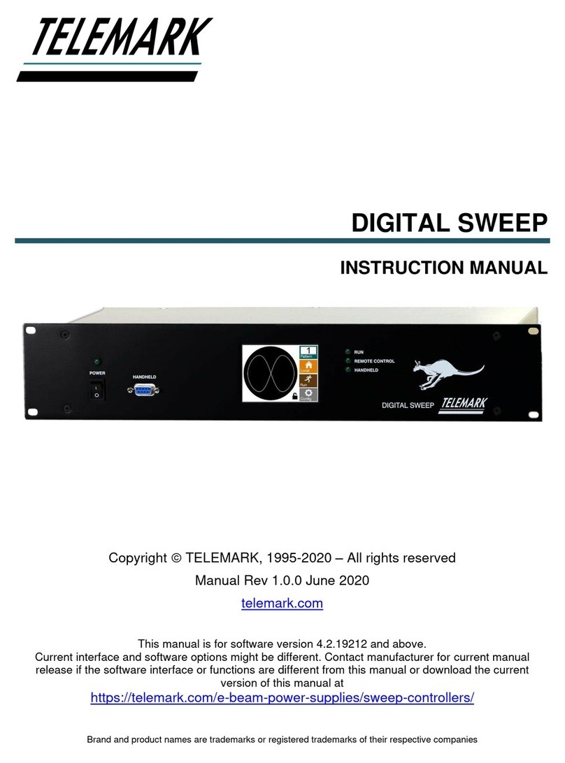
Telemark 880 User manual

Telemark
Model 880
Thin Film
Deposition Controller
Users Manual
June 7 2003,
518-030 Preliminary
MANUAL
CONTROL
RATE-A/SEC POWER-% THICKNESS-KA
START
STOP
MANUAL ZERO
MODEL 880
DEPOSITION CONTROLLER
MENU
STATUS

p
Model 880 DEPOSITION CONTROLLER
y
SECTION 0.XX epage 1 of 275 ^
TFC-2002 JM
USERS MANUAL 518-030
Rev <preliminary> June 7, 2003
.current:
Telemark Model 880 Deposition Controller
>
MANUAL
CONTROL
RATE-A/SEC POWER-% THICKNESS-KA
START
STOP
MANUAL ZERO
MODEL 880
DEPOSITION CONTROLLER
MENU
STATUS
>
WARNING
!
The power cord protective
grounding conductor must be
connected to ground. No user
serviceable parts inside. Refer
servicing to qualified personnel.
FUSE: 2 x 2.00 AMP
QUICK-ACTING (F) 250v
90-264 vac, 50-60 Hz, 230VA MAX
INPUTS / OUTPUTS
SOURCE
SENSORS
I/O 4 1/O 3 I/O 2 I/O 1
COMM OPTION
RS232 MEM
7 5 3 1
8 6 4 2
7 5 3 1
8 6 4 2
.overview w/ generalizations only
intro to user interface, overview from general to specific
=
overview w/ generalizations and intro to specifics as generalizations are developed.
<Telemark reserves the right to change any information contained in this manual without notice
©Copyright Sycon Instruments, Inc. & Telemark 2003
AMPHENOL®is a registered trademark of Allied Corporation
AMP®is a registered trademark of Tyco/Amp, Inc.
ConFlat®is a registered trademark of Varian Associates, Inc.
IBM®Is a registered trademark of IBM Corporation
Microsoft®is a registered trademark of Microsoft Corporation
Microdot ®is a registered trademark of Microdot Inc.
SWAGELOK®is a trademark owned by Crawford Fitting Company
Windows® is a registered trademark of Microsoft Corporation
.

p
Model 880 DEPOSITION CONTROLLER
y
SECTION 0.XX epage 2 of 275 ^
Warranty.
The model 880 Deposition Controller is guaranteed against faulty materials, function, and workmanship for
a period of 12 months after delivery from Telemark. Components which are purchased by Telemark from
other manufactures will be guaranteed for any lesser time that such manufacturer warrants its product to
Telemark. This warranty is valid only for normal use where regular maintenance is performed as instructed.
This warranty shall not apply if repair has been performed or an alteration made by anyone other than an
authorized Telemark representative or if a malfunction occurs through abuse, misuse, negligence, or
accident. No charge will be made for repairs made under warranty at Telemark's facilities. Freight costs
both ways will be at customer's expense. Telemark reserves the right for final warranty adjustment.
User Responsibility
The user is responsible for proper operation an ordinary maintenance of the equipment, following
procedures described in this manual, including reference documents. Proper operation includes timely
replacement of parts that are missing, broken, or plainly worn. If the user has a reasonable doubt about
understanding the use or installation of a component, Telemark Technical Service should be called.
It is vitally important that the user properly install the equipment as described in the Installation sections of
this manual. The warranty will be void if the equipment is improperly installed.
Alteration of the design or any function of the equipment voids the warranty and is entirely the
responsibility of the user.
Safety Warning
General Precautions: Human contact with the voltages present within and around a vacuum system can be
fatal. Make sure that the input power is turned off before opening the doors or removing panels. Short all
HV feedthrough connections with a grounding hook before accessing the controller main body.
Disclosure
The disclosure of this information is to assist owners of Telemark equipment to properly operate and
maintain their equipment, and does not constitute the release of rights hereof. Reproduction of this
information and equipment described herein is prohibited without prior written consent from Telemark.

p
Model 880 DEPOSITION CONTROLLER
y
SECTION 1.XX epage 3 of 275 ^
SECTION 1.0 Introduction
.specifications/included materials
(no intro here) unpacking.
Unpacking
The Model 880 comes with a power cord and connectors for the RS-232 interface, the I/O
interfaces and analog outputs (see the following spare parts included list). If the essential OSC-100A
oscillator or crystals were ordered at the same time, they will also be included. The unit operates from 90
to 264 VAC with no adjustments required. If it is ever necessary to return the unit to Telemark, for any
reason, call and obtain a Return Material Authorization number (RMA#).
Description
The Model 880 provides both automatic control of single or multi-layer film deposition in either a
production or development environment and improved predictability and repeatability of deposited film
characteristics through dependable digital control of the deposition process. It runs unattended in the fully
automatic mode and provides a wide number of benefits including performance limit access and setting by
the end user.
SECTION 1.1 MANUAL DESCRIPTION
.[please read and understand this manual before proceeding w/ equipment useage].
Please read and understand the contents of this manual before proceeding with equipment useage in a
working system. This manual will take the reader through the appropriate setup and example steps,
providing along the way, an understanding of how the Model 880 instrument is used. A test mode is
available from the SERVICE menu for simulated out of system experiments. Crystal sensor head
information is simulated (actually rate info is simulated for the film) allowing setup of various
parameters/programming elements without crystal failure halting the simulated process. The power supply
control voltage output is, however, active while in the test mode. All these terms will be described shortly.
This manual is organized into a number of main sections: specifications, generalized overview,
menu programming specifics and setup, hardware setup, detailed host communications, microbalance
theory and maintenance. If any further assistance is needed, please contact Telemark (see section 1.6).
The specifications section describes Model 880 product specifics, both hardware and software,
along with related necessary and optional product specifics. The software specifics include programmable
parameter lists. The generalized overview section answers the what, the how is it used and the how does it
work questions about the Model 880, that is, the solutions this product can provide. This section is intended
to discuss the concepts of main functions and elements with only enough detail to make the
conceptualization clear. In addition, rudimentary specifics are given in a number of other areas as an
introduction or a primer for the next section. This is information you typically only need to look at once.
Experienced users (those familiar with deposition controllers) should at least thumb through this section to
take an inventory of what is available. The menu programming specifics and operational details section
provides detailed information about product programming. Experienced users (those familiar with
deposition controllers) may decide to start here. If some elements are unclear, check back to the previous
section. The table of contents and index are helpful in this pursuit. This section provides descriptions for the
programming of film parameters and process steps, descriptions of menu navigation, descriptions of
screens, descriptions of fixed front panel keys, descriptions of run modes, parameter details, memory
defaults, programming summaries, etc. The hardware setup section describes and illustrates connectors,
interconnections, peripherals, mechanical connections, and the Model 880 as a component in a larger
system. Detailed host communications are found in the following section x6. See section x7 for

p
Model 880 DEPOSITION CONTROLLER
y
SECTION 1.XX epage 4 of 275 ^
Microbalance theory and thickness reading calibration with its attendant density, z factor (a material
reference table of elements is included) and tooling determination. Each section builds on the previous
sections such that no new elements are used that haven't been defined.
.Some sage advice that is
seldom heeded.
.
SECTION 1.2 DESCRIPTION OF SYMBOLS
.note the following warning/safety/caution symbols [desc. of each].
Please familiarize yourself with the following warning/safety/caution symbols found within this manual
and their general meaning:
Note: Highlights an important fact or condition.
Caution: Warns of a condition that could cause damage to deposition controller, connected or
associated equipment. Also warns if some action taken could result with an undesireable and/or
unexpected outcome.
or
!: Warns of a condition that will likely cause damage to the deposition controller, connected or
associated equipment. Also warns of a possible unsafe situation for the user. Examples are static
sensitivities, maximum component ratings, broken fuses, etc.
or
: Warns of a condition that is hazardous to user, deposition controller, connected or associated
equipment.
Note
Caution
Static
Sensitive
Hazardous
Voltages
Present
You can lead a customer to water
b
ut you can't make them read the
manual.
If all else fails
read the manual.

p
Model 880 DEPOSITION CONTROLLER
y
SECTION 1.XX epage 5 of 275 ^
SECTION 1.3 TABLE OF CONTENTS
TITLE PAGE................................................................................................................................................ 1
WARRANTY ................................................................................................................................................ 2
INTRODUCTION [1.XX] ............................................................................................................................ 3
SECTION 1.0 ................................................................................................................................................ 3
Unpacking Instructions........................................................................................................................... 3
SECTION 1.1 ................................................................................................................................................ 3
Manual Description: Usage, Organization, Section Contents Summary ............................................... 3
SECTION 1.2 ................................................................................................................................................ 4
Description of Symbols Found in Manual .............................................................................................. 4
SECTION 1.3 TABLE OF CONTENTS...................................................................................................... 5
SECTION 1.4 .............................................................................................................................................. 11
STC-Spare Parts (included w/ Model 880)........................................................................................... 11
STC-Optional Parts .............................................................................................................................. 11
SECTION 1.5 .............................................................................................................................................. 11
STC-Optional Crystal Sensor Parts...................................................................................................... 11
SECTION 1.6 .............................................................................................................................................. 12
Contact Information ............................................................................................................................. 12
SECTION 1.7 .............................................................................................................................................. 13
Product Specifications.......................................................................................................................... 13
SECTION 1.8 ............................................................................................................................................. 14
Programmable Parameter Lists........................................................................................................... 14
Programmable Parameter Dependency Lists ..................................................................................... 17
SECTION 1.9 .............................................................................................................................................. 19
Sensor Specifications............................................................................................................................ 19
SIMPLE QUICK GENERALIZED OVERVIEW [2.XX] ..................................................................... 21
SECTION 2.0 .............................................................................................................................................. 21
For What Is The Model 880 Used? [The Problem, The Solution]........................................................ 21
SECTION 2.1 .............................................................................................................................................. 22
How Is It Used?.................................................................................................................................... 22
SECTION 2.2 .............................................................................................................................................. 26
How Does It Work? .............................................................................................................................. 26
Hardware Setup Discussion ................................................................................................................. 29
Sensor Head: Hardware Generalizations............................................................................................. 30
Power Supply Connection .................................................................................................................... 32
Strip Chart Recorder Connection......................................................................................................... 32
RS-232 Communications Connection ................................................................................................... 32
Grounding Stud .................................................................................................................................... 33
Input Card Options............................................................................................................................... 33
Installation/Removal Of Sensor Cards, Input Cards, Output Cards .................................................... 34
Pendant (hand controller) .................................................................................................................... 35
LCD Contrast/Bias ............................................................................................................................... 35
Graphical Display ................................................................................................................................ 35
Mounting .............................................................................................................................................. 35
System Hardware Connections............................................................................................................. 35
Programmable Hardware Setup Discussion ........................................................................................ 36
Select RunTime Mode: Sequencing/Non-Sequencing, Manual Mode, Test Mode............................................ 36
Memory Storage of Menu Parameters ............................................................................................................... 36
Films & Processes / Active, Non-Active ........................................................................................................... 36
Menu Parameter Dependencies.......................................................................................................................... 36
Tooling: Material Density & Z-Factor............................................................................................................... 37

p
Model 880 DEPOSITION CONTROLLER
y
SECTION 1.XX epage 6 of 275 ^
Power Related Menu Parameters ....................................................................................................................... 37
Power Related Menu Parameter Dependencies ................................................................................................. 38
Initial Programming Setups (menu parameters) .................................................................................. 40
Menu Parameter Values & Programming After Memory Purge........................................................................ 40
Menu Parameter Values & Programming After Factory Restored Memory ...................................................... 41
I/O Programming Introduction ............................................................................................................ 42
Boolean Logic Discussion ................................................................................................................................. 43
Simple I/O Program Examples .......................................................................................................................... 44
How To Develop I/O Programs............................................................................................................ 48
MENU PROGRAMMING AND OPERATION DETAILS [3.XX] ...................................................... 49
SECTION 3.0 .............................................................................................................................................. 49
LCD Touch Panel Overlay ................................................................................................................... 49
Front Panel Definitions ........................................................................................................................ 50
SECTION 3.1 .............................................................................................................................................. 56
Navigating Through Model 880 Menus................................................................................................ 56
Menu Tree............................................................................................................................................. 57
SECTION 3.2 .............................................................................................................................................. 58
RunTime Screen Description ................................................................................................................ 58
SECTION 3.3 .............................................................................................................................................. 60
Main Menu Description........................................................................................................................ 60
SECTION 3.4 .............................................................................................................................................. 63
Films And Processes............................................................................................................................. 63
SECTION 3.5 .............................................................................................................................................. 63
Film Edit/Review Mode ........................................................................................................................ 63
Film Parameter Checksum................................................................................................................................. 67
Film Parameter Lock Code ................................................................................................................................ 67
Film Parameter: Source Sensor Map Select....................................................................................................... 68
Review SS MAP................................................................................................................................................ 68
Selecting the Active Film in Non-Sequencing Mode......................................................................................... 69
Detailed Film Parameter Descriptions ................................................................................................ 71
Detailed Map Parameter Descriptions................................................................................................. 79
SECTION 3.6 ............................................................................................................................................. 83
Editing Processes................................................................................................................................. 83
Process Lock Code ............................................................................................................................................ 93
Factory Restoration vs. Purged Settings ............................................................................................................ 93
Changing Memory Settings ............................................................................................................................... 93
SECTION 3.7 .............................................................................................................................................. 93
Set Active Process................................................................................................................................. 93
SECTION 3.8 .............................................................................................................................................. 94
Non-Sequencing Differences ................................................................................................................ 94
SECTION 3.9 .............................................................................................................................................. 96
Software Controlled RunTime Screen Keys.......................................................................................... 96
L/Q key (Crystal Quality).................................................................................................................................. 96
SMPL key (Sample and Hold)........................................................................................................................... 96
SECTION 3.10 ............................................................................................................................................ 97
Manual Power Control......................................................................................................................... 97
Using Pendent.................................................................................................................................................... 97
Using LCD keys ................................................................................................................................................ 98
SECTION 3.11 ............................................................................................................................................ 99
Model 880 Shutter Delay...................................................................................................................... 99
SECTION 3.12 ............................................................................................................................................ 99
Deposition Source Control Loop Description ...................................................................................... 99
SECTION 3.13 .......................................................................................................................................... 101
Film Phases And Parameter Groups.................................................................................................. 101
SECTION 3.14 .......................................................................................................................................... 102
System Configuration ......................................................................................................................... 102
SECTION 3.15 .......................................................................................................................................... 103

p
Model 880 DEPOSITION CONTROLLER
y
SECTION 1.XX epage 7 of 275 ^
Detailed System Configuration Related Parameters .......................................................................... 103
SECTION 3.16 .......................................................................................................................................... 105
Communications Configuration Related Parameters......................................................................... 105
Detailed Communications Configuration Related Parameters......................................................................... 106
SECTION 3.17 .......................................................................................................................................... 108
Model 880 Crystal Failure Processing............................................................................................... 108
SECTION 3.18 .......................................................................................................................................... 112
Process Accounting ............................................................................................................................ 112
SECTION 3.19 .......................................................................................................................................... 114
OPTions/INFo .................................................................................................................................... 114
Checksum Validation ........................................................................................................................ 115
Checksums And Parameters After Purge............................................................................................116
SECTION 3.20 .......................................................................................................................................... 118
Memory Module Programming & Usage ........................................................................................... 118
Memory Module Data Transfer ....................................................................................................................... 120
Memory Module Placement............................................................................................................................. 121
SECTION 3.21 .......................................................................................................................................... 122
Programming Example....................................................................................................................... 122
Entering The TEST Mode................................................................................................................................ 122
SECTION 3.22 .......................................................................................................................................... 130
Product Programming Summary........................................................................................................ 130
ELECTRICAL CONNECTIONS AND DESCRIPTIONS [4.XX] ..................................................... 135
SECTION 4.0 ............................................................................................................................................ 135
Sensor Head Installation .................................................................................................................... 135
SECTION 4.1 ............................................................................................................................................ 138
Electrical Connections And Descriptions........................................................................................... 138
SECTION 4.2 ............................................................................................................................................ 138
Line Power ......................................................................................................................................... 138
SECTION 4.3 ............................................................................................................................................ 138
Rack Mounting.................................................................................................................................... 138
SECTION 4.4 ............................................................................................................................................ 138
Vacuum System Grounding ................................................................................................................ 138
SECTION 4.5 ............................................................................................................................................ 140
Sensor Connections ............................................................................................................................ 140
SECTION 4.6 ............................................................................................................................................ 140
Analog Control Voltage Connections................................................................................................. 140
Control Voltage Output Connection................................................................................................... 140
SECTION 4.7 ............................................................................................................................................ 141
Analog Recorder Output Connection ................................................................................................. 141
Analog Recorder Output Specifications ............................................................................................. 141
SECTION 4.8 ............................................................................................................................................ 143
I/O Interface ....................................................................................................................................... 143
SECTION 4.9 ............................................................................................................................................ 146
Relay Outputs (Factory I/O Program) ............................................................................................... 146
SECTION 4.10 .......................................................................................................................................... 147
Remote Inputs (Factory I/O Program) ............................................................................................... 147
SECTION 4.11 .......................................................................................................................................... 147
RS-232 Serial Communications Interface........................................................................................... 147
SECTION 4.12 .......................................................................................................................................... 148
Communications Options ................................................................................................................... 148
I/O PROGRAMMING [5.XX]................................................................................................................ 149
SECTION 5.1 ............................................................................................................................................ 149
I/O Programming Introduction .......................................................................................................... 149
SECTION 5.2 ............................................................................................................................................ 153

p
Model 880 DEPOSITION CONTROLLER
y
SECTION 1.XX epage 8 of 275 ^
Boolean Definitions ............................................................................................................................ 153
SECTION 5.3 ............................................................................................................................................ 154
States And Events ............................................................................................................................... 154
SECTION 5.4 ............................................................................................................................................ 159
Steady State vs. Edges ........................................................................................................................ 159
SECTION 5.5 ............................................................................................................................................ 159
Input Functions................................................................................................................................... 159
SECTION 5.6 ............................................................................................................................................ 160
Output Functions................................................................................................................................ 160
SECTION 5.7 ............................................................................................................................................ 160
Softnodes And Sync Events ................................................................................................................. 160
SECTION 5.8 ............................................................................................................................................ 161
Internal Operations ............................................................................................................................ 161
SECTION 5.9 ............................................................................................................................................ 162
Operate Menu..................................................................................................................................... 162
SECTION 5.10 .......................................................................................................................................... 162
Memory Menu..................................................................................................................................... 162
SECTION 5.11 .......................................................................................................................................... 163
Editing An I/O Program ..................................................................................................................... 163
I/O Programming Tree ....................................................................................................................... 165
SECTION 5.12 .......................................................................................................................................... 168
I/O Setup Edit Menu ........................................................................................................................... 168
SECTION 5.13 .......................................................................................................................................... 169
Edit/Change Menu.............................................................................................................................. 169
COMPUTER INTERFACING [6.XX] .................................................................................................. 191
SECTION 6.0 ............................................................................................................................................ 191
Host Port Interface ............................................................................................................................. 191
THEORY AND CALIBRATION [7.XX] .............................................................................................. 261
SECTION 7.0 MEASUREMENT THEORY.................................................................................................... 261
Equation 1 .......................................................................................................................................... 261
SECTION 7.1 CALIBRATION..................................................................................................................... 262
Thickness ............................................................................................................................................ 262
Density Determination....................................................................................................................... 262
Z-Factor Determination ..................................................................................................................... 262
Tooling Dtermination ......................................................................................................................... 262
Material Reference Table:.................................................................................................................. 264
Aluminum Through Indium............................................................................................................................. 264
Indium Intimonide Through Terium................................................................................................................ 265
Thallium Through Zirconium Oxide................................................................................................................ 266
MAINTENANCE/PROBLEM SOLUTIONS [8.XX]........................................................................... 267
SECTION 8.0 ............................................................................................................................................ 267
Warnings/Cautions ............................................................................................................................. 267
User Correctable System Problems.................................................................................................... 267
SECTION 8.1 REPLACING A SENSOR CRYSTAL ....................................................................................... 268
Cautions/Procedural Steps................................................................................................................. 268
SECTION 8.2 PERSISTENT CRYSTAL FAIL INDICATION ........................................................................ 268
Discussion .......................................................................................................................................... 268
Hardware Issues................................................................................................................................. 269
SECTION 8.3 FAQS................................................................................................................................270
SECTION 8.4 SYSTEM BATTERY AND MEMORY CONSIDERATIONS ..................................................... 270
Procedure to Change Battery ............................................................................................................. 270
GLOSSARY .............................................................................................................................................. 271

p
Model 880 DEPOSITION CONTROLLER
y
SECTION 1.XX epage 9 of 275 ^
INDEX ....................................................................................................................................................... 273
COPY PARAMETER LISTS.................................................................................................................. 274
FIGURES
Standard Sensors.................................................................................................................................. 20
Sequencing / Non-Sequencing Modes................................................................................................... 23
Process / Film / Map Relationships...................................................................................................... 25
Back Panel Connections (Overview) .................................................................................................... 29
Electrical Connections From Crystal Through Remote Oscillator (Overview) ................................... 30
Input Bd. Jumpers (Overview).............................................................................................................. 33
Installation/Removal Of Back Panel PCB Cards ................................................................................. 35
I/O Programming Notation .................................................................................................................. 44
I/O Programming Description.............................................................................................................. 44
I/O Programming: User Programmable Front Panel Keys/LEDs ....................................................... 45
Example I/O Programs......................................................................................................................... 45
I/O Programming: Modulo 100 Counter Addresses............................................................................. 47
Touch Panel Overlay............................................................................................................................ 49
Front Panel and Key Descriptions ....................................................................................................... 50
Typical RunTime Screen....................................................................................................................... 50
Status Key Screens................................................................................................................................ 51
Manual Mode Screens .......................................................................................................................... 52
Status Screen Selector Function ........................................................................................................... 54
Start Key Menu..................................................................................................................................... 54
Start (Key) Process Flowchart ............................................................................................................. 55
Menu Tree............................................................................................................................................. 57
RunTime Screen.................................................................................................................................... 58
Main Menu Screen................................................................................................................................ 60
Executive Menu .................................................................................................................................... 62
Films & Process Storage...................................................................................................................... 63
Review Film Menu................................................................................................................................ 64
Non-Sequencing Mode Screen.............................................................................................................. 69
Rate Sampling, Sample And Hold Operation ....................................................................................... 75
Main Process Review/Edit Screen ........................................................................................................ 83
Service Menu, Memory Configurations................................................................................................ 93
Setting the Active Process (Sequencing Mode)..................................................................................... 94
Setting The Active Film (Non-Sequencing Mode.................................................................................. 94
RunTime Screen (Non-Sequencing Mode)............................................................................................ 95
RunTime Screen: L/Q ........................................................................................................................... 96
RunTime Screen: Sample & Hold......................................................................................................... 96
Hand Controller/Pendent ..................................................................................................................... 97
Manual Power Control......................................................................................................................... 98
Typical Run Cycle............................................................................................................................... 101
System Configuration Screens ............................................................................................................ 102
Communications Menu Screen ........................................................................................................... 105
Process Accounting Screens............................................................................................................... 112
Options Info Screens........................................................................................................................... 114
Memory Module.................................................................................................................................. 118
RunTime Screen With Test Mode Enabled ......................................................................................... 122
Electrical Connections To Back Panel ............................................................................................... 135
Crystal Head Mounting ...................................................................................................................... 135
Rear Panel.......................................................................................................................................... 138
Recommended System Grounding ...................................................................................................... 139

p
Model 880 DEPOSITION CONTROLLER
y
SECTION 1.XX epage 10 of 275 ^
Rate Mode Recorder Output............................................................................................................... 142
I/O: Input Configuration Jumpers...................................................................................................... 143
I/O: Input Configuration Jumpers...................................................................................................... 145
RS232 Interface Cable........................................................................................................................ 148
I/O Programming Menu Screen.......................................................................................................... 149
Relay Ladder Notation........................................................................................................................ 153
Stack I/O Operations .......................................................................................................................... 161
I/O Programming Menu Screen Descriptions .................................................................................... 163
I/O Programming Menu Tree............................................................................................................. 165
I/O Programming Menu Descriptions ................................................................................................ 166
I/O Programming Edit Menu Description .......................................................................................... 168
I/O Programming EDT/CHG Screens 1-5.......................................................................................... 171
I/O Programming: I/O program Entry............................................................................................... 174
I/O Programming: Inserting An Empty Rung..................................................................................... 179
I/O Programming: Changing the Rung ..............................................................................................179
I/O Usage of Hand Controller/Pendent.............................................................................................. 188
Making An RS232 Cable..................................................................................................................... 191
Communications Setup Mode ............................................................................................................. 193
Equation 1 .......................................................................................................................................... 261
Density Calculation ............................................................................................................................ 262
Z-Factor Calculation.......................................................................................................................... 262
Typical Tooling Factors ..................................................................................................................... 263
Sensor Feedthrough Connections....................................................................................................... 269
TABLES
FACTORY SETTINGS, PROCESS PROGRAMS ............................................................................................... 41
BOOLEAN LOGIC ....................................................................................................................................... 43
FACTORY SETTINGS, PROCESS PROGRAMS ............................................................................................... 93
PHASES AND PARAMETERS ..................................................................................................................... 101
CHECKSUMS AFTER PURGED / AFTER FACTORY RESTORED MEMORY ................................................... 116
PRODUCT PROGRAMMING SUMMARY TABLES ........................................................................................ 130
FACTORY RELAY OUTPUT PROGRAM ...................................................................................................... 146
TRUTH TABLE ......................................................................................................................................... 154
EVENT AND STATE ID LIST .................................................................................................................... 155
EVENT AND STATE ID LIST .................................................................................................................... 158
FACTORY INSTALLED I/O PROGRAM....................................................................................................... 181
MODULO 6 COUNTER PROGRAM ............................................................................................................. 185
FIXED DELAY & PULSE WIDTH I/O PROGRAM........................................................................................ 186
RESPONSE CHARACTER TABLE ............................................................................................................... 194
MATERIAL REFERENCE TABLE................................................................................................................ 264

p
Model 880 DEPOSITION CONTROLLER
y
SECTION 1.XX epage 11 of 275 ^
SECTION 1.4
.included parts: STC-2002, power cord, spare parts.
Model 880 Spare Parts (included with Model 880)
ASSEMBLY PARTNUMBER
POWER CORD [120 VAC] (1) 600-004
FUSES (2 x 2.00A 250VAC F-type) 356-014
OPTOCOUPLED INPUTS 25 PIN MALE CONNECTOR (1) 402-222
RELAY OUTPUTS 25 PIN FEMALE CONNECTOR (1) 404-020
EMI HOOD FOR 25 PIN CONNECTORS (2)..........................404-021
RS-232 9 PIN MALE CONNECTOR (1)..................................404-011
EMI HOOD FOR 9 PIN CONNECTOR (1)..............................404-009
RACK MOUNT EARS (2) ........................................................016-012
RACK MOUNT HDWR (4) ......................................................094-006
MANUAL (this manual)................ ............................................518-029
CONNECTOR KIT / PARTS ....................................................516-017
HAND CONTROLLER (1) .......................................................500-198
COMMUNICATIONS SOFTWARE TOOLS DISK (1)...........500-046
Optional Model 880 Hardware / Software
MEMORY MODULE/STRIP CHART INTERFACE PCB 500-212
TRANSPORTABLE MEMORY MODULE (32K) ..................500-210
TRANSP. MEMORY MODULE SOFTWARE FOR PC..........500-TBD
TRANSP. MEMORY MODULE CABLE FOR PC..................500-TBD
SECTION 1.5
Optional Sensor Parts
Description................................................................. Telemark Part Number
Sensor Body (Low Profile) .......................................................550-222
Sensor Cap (Low Profile)...........................................................550-223
30 inch In-Vacuum Coax Cable ................................................500-024
10 inch In-Vacuum Coax Cable ................................................500-023
Crystals (box of 10) ...................................................................500-117
Standard Feedthroughs
1" BOLT STANDARD .............................................................500-016
2 3/4" ConFlat STANDARD ....................................................500-017
Standard Sensors
LOW PROFILE .........................................................................500-042
RIGHT ANGLE.........................................................................500-088

Model 880DEPOSITION CONTROLLER
SECTION 1.XX page 12 of 275
Cables
10' OSC TO CONTROL UNIT CABLE ...................................500-026
30' OSC TO CONTROL UNIT CABLE ...................................500-027
6" OSC TO FEEDTHROUGH COAX CABLE ........................500-025
Crystal / Oscillator Package (includes the following 4 item numbers) 500-109
6" OSC TO FEEDTHROUGH COAX CABLE ........................500-025
10' OSC TO CONTROL UNIT CABLE ...................................500-026
OSCILLATOR UNIT ...............................................................OSC-100A
10 CRYSTALS ..........................................................................500-117
SECTION 1.6 Contact Information
Model 880
Model 880 DEPOSITION RATE CONTROLLER
Sensor Package and Feedthrough Not Included
Website www.telemark.com

p
Model 880 DEPOSITION CONTROLLER
y
SECTION 1.XX epage 13 of 275 ^
SECTION 1.7 PRODUCT SPECIFICATIONS
Model 880 Thin-Film Thickness and Rate Controller Specifications
High Resolution ±0.02Hz(5-6MHz), 0.0088 Angstroms/Measurement (for Aluminum)
High Accuracy ±0.5% thickness + 1 count
High Speed Ten measurements/second
Measurement Range 500KA Aluminum Equivalent
Standard Sensor Crystal 6 MHz AT cut, Plano/Convex
Sensor Capacity 2 per sensor PCB card [4 PCB cards max.]
Displays 240 x 64 pixel monochrome LCD with Backlight
12 digit LED display (7 segments each digit)
4 discrete indicator LEDs
Operation Menu driven "Windowing Type"
LCD Touch Panel (12 x 4 key matrix)
with 6 fixed function membrane keys
and 4 user programmable fixed membrane keys
Film Storage (Standard) 1 Active Film Program
98 Alternate Film Programs (with 30 Sensor maps)
9 Sequence recipes, 99 steps per recipe, system total is 250 steps
External Storage (Optional) Film Parameters for films 1-99 and System Parameters I/O programs,
and Process Accounting Can be stored in Transportable Data Module
(Optional)
Hardware I/O (Standard) per card: 8 SPDT Relays, 1.0 Amp @ 24 VDC Maximum
per card: 8 Optocoupled Inputs (Electrically Isolated), 5-24VDC [4
slots for input and/or output cards]
Computer Interface RS-232C (Sycon Format or ASCII)
Protocols
Communication Options DeviceNet, PROFIBUS, CANopen, others
Analog Outputs: 12 bit resolution (2 per sensor card, each for use as control or recorder)
As Control Outputs 2.5, 5, 10 volt @10ma. isolated output with range
menu programmable (maximum 2 control outputs per sensor card)
As Recorder Outputs 0 to 10 volt @ 10ma, isolated, function programmable
(rate, thickness, power, deviation, computer remote) (maximum 1
recorder output per sensor card and per system)
Power Control:
Automatic Three Mode Closed Loop Control (PID)
Manual Hand Controller
Rack Mount full width rack mount (std.). 3 1/2" H, 8 5/8" D
Power Requirements 90-264VAC, 50-60Hz (1.4A rms@120VAC, 0.7A rms@230VAC)
Weight (without options) 6 lbs. [with: 1 Sensor card, 1 Input Card, 1 Output Card] Sensor
card=0.216 lbs., Input card=0.135 lbs., Output card=0.14 lbs.
Operating Range 0 to 50°C ambient (power supply/LCD display)
Humidity non-condensing: 5% - 85% RH

p
Model 880 DEPOSITION CONTROLLER
y
SECTION 1.XX epage 14 of 275 ^
SECTION 1.8 Programmable Parameter Lists
.programmable parameter list (1.4).
__________________________________________________________________
key examples:
Full Parameter Name ⇒Abbreviated Menu Name
Parameter Name ⇒Param N
(text) ⇒implied parameter text in parenthesis
__________________________________________________________________
Film Parameter List:
Review Film (Edit Film) [Menu end point: Review Film Menu path: Main/Review Film]
(Material) Density 0.40 to 99.99 gm/cc
(Material) Z-Factor 0.100 to 9.999
Setpoint Thickness Limit 0.000 to 999.999 KÅ
Final Thickness Limit (Trigger) 0.000 to 999.999 KÅ (non-sequencing only)
Setpoint Time Limit 0:00 to 99:59 MM:SS
Soak 1 Power level Value 0.0 to 100.0%
Power Ramp 1 Time (to pwr level) 0 to 99:59 MM:SS
Power Soak 1 Time (@ pwr level) 0 to 99:59 MM:SS
Soak 2 Power level Value 0.0 to 100.0%
Power Ramp 2 Time (to pwr level) 0 to 99:59 MM:SS
Power Soak 2 Time (@ pwr level) 0 to 99:59 MM:SS
Soak 3 Power level Value 0.0 to 100.0%
Power Ramp 3 Time (to pwr level) 0 to 99:59 MM:SS
Deposit Rate (requested) 0.0 to 999.9 A/S
Rate Ramp Mode OFF / ON
New Deposit Rate (Value) 0.0 to 999.9 A/S
Rate Ramp Time (Duration) 0:00 to 99:59 MM:SS
Rate Ramp (Thickn) Trigger Point 0 to 999.999 KÅ
Control Loop –Proportional term- 1 to 9999
Control Loop –Integral term- 0.0 to 99.9 sec
Control Loop –Derivative term- 0.0 to 99.9 sec
Max Power Limit 0.0 to 100.0%
Abort Max Power SWitch OFF/ON
Max Power Dwell 0:01-99:59 MM:SS
Shutter Delay Mode OFF, ON
Shutter Delay TIMEOUT 0:01-99:59 MM:SS
Shutter Delay QUALITY 1-50%
(XTAL) RATE SAMPLING OFF,TIMED,INTELL.
(XTAL) SAMPLE INTERVAL 0:01-99:59 MM:SS
(XTAL) SAMPLE DWELL TIME 0:01-99:59 MM:SS
(XTAL) SAMPLE QUAL 1-50%
(XTAL) SAMPLE ALARM TIME 0:01-99:59 MM:SS
FILM Fail Mode ABORT IF FAIL, TIME POWER
Control Loop Qual Limits 0 to 9
XTAL Stability S (Limits) 0 to 9
XTAL Life Bounds 0.0-100.0%
Plot Vert ScaleVolts 1, 5, 10, 50, 100
Plot Horiz ScaleH 1 to 600 samples
Data Plot Type Rate /Rate Deviation /Power

p
Model 880 DEPOSITION CONTROLLER
y
SECTION 1.XX epage 15 of 275 ^
Source Sensor MAP SELECT 1 - 30
POCKET SELECT 0 – 63 Pockets
ETCHING MODE OFF/ON
Process Step elements: [Menu end point: Review Processes Menu path: Main/Review Processes]
Review Processes (Edit Process) (Edit Process Steps [1-99]) Mode (Skip, Stop, Auto,
End, Wait), Film# (1-99), Thickness (0.0 - 999.999 KÅ)
Main Menu values: [Menu end point: Main Menu Menu path: fixed front panel MENU key/ Main Menu]
Next Active Process (Select)* 1 of 9 processes [sequencing mode only]
Next Active Film (Select)* 1 of 99 films [non-sequencing mode only]
[*NOTE: press touch key enclosing digit to select 1 of the 9 processes or 99 films (press digits + ENTer on invoked submenu)]
RunTime Screen parameters:
[Menu end point: RunTime screen Menu path: programming Menu/ fixed front panel STATUS key/RunTime screen]
(Crystal Quality Indicator Select) L/Q, Loop x, Qual xx
(Crystal Sample Select) (not selected [blank]), SMPL, SMPL+Time, HOLD+Time
START key sequence (fixed front panel) (Note PROCess X: message change after each START process key press)2
STOP key (fixed front panel) Stops the running process (non-seq mode: stops the 1 inherent process [film])
MANUAL key (fixed front panel) Switches to manual mode from a running process only. Toggle action.
ZERO key (fixed front panel) Zeroes the thickness value
MENU key (fixed front panel) Switches from RunTime screen to MAIN menu screen
STATUS key (fixed front panel) Switches to RunTime screen from any menu screen, to detailed power
and crystal info screens from RunTime screen
Zero Power [non-active process] zero channel 1-8, zero all [1st STATUS key press from RunTime]
Zero Thickness1zero channel 1-8, zero all, re-verify [2nd STATUS key press from RunTime]
Force Fail [non-active process]
fail channel 1-8, fail all, re-verify [2nd STATUS key press from RunTime]
1Zero thickness does not affect film thickness value, only Source Sensor card value (use to set tooling factor, diagnose
problems, etc. )
2If the PROCess X: status message does not change when the START key is pressed, check for "STOP: INValid XXX "
message or check the OPT/INF menu, page 2 for cards not installed which are enabled in software (MIA). Cycle AC power
OFFON to re-sync.
System Configuration values: [Menu end point: System Config Menu path: Main/Executive menu/System Configuration]
LCD Contrast / Bias LOW, MEDIUM, HIGH
Password Lock # 0 - 9999
(Process) Run Number 0 to 9999
Recorder Function Absolute Rate, Rate Deviation, Power, Thickness, Computer Remote, I/O Control, Off
Recorder Out Channel 1 – 8 selects an analog output channel for use (if not off and not used as a source)
Real Clock Time HH/MM
Real Clock Date MM/DD/YY
Need Source/Sensor Card 1 OFF/ON
Need Source/Sensor Card 2 OFF/ON
Need Source/Sensor Card 3 OFF/ON
Need Source/Sensor Card 4 OFF/ON
I/O Slot 1 Type UNUSED (DISABLED) / INPUT / OUTPUT
I/O Slot 2 Type UNUSED (DISABLED) / INPUT / OUTPUT
I/O Slot 3 Type UNUSED (DISABLED) / INPUT / OUTPUT
I/O Slot 4 Type UNUSED (DISABLED) / INPUT / OUTPUT
Memory Module IFC OFF/ON
Communication values: [Menu end point: Comm. Setup Menu path: Main/Executive menu/Communications Setup]
COM/IO Lock Code 0 - 9999
Keyboard Beep OFF / ON
RS232 Baud Rate 300, 1200, 2400, 9600
RS232 Protocol Sycon, ASCII

p
Model 880 DEPOSITION CONTROLLER
y
SECTION 1.XX epage 16 of 275 ^
Source Sensor Map elements: [Menu end point: Review SS Map Menu path: Main/Review SS Map]
Source Sensor Full Power Volts 2.5, 5, 10 full scale volts
Source Sensor Max Power Value 0.0% - 100.0%
Source Sensor Analog Output Chnl 1 – 8 Channel Selection
Master Tooling Value 10.0% - 400.0%
Minimum Start Xtal Channels 1 – 8 minimum channels
Minimum Backup Xtal Channels 0 – 7 minimum channels
Minumum Active Xtal Channels 1 – 8 minimum channels
(Xtal) Channel Drop Filter NONE, BALANCE [Mask dropped Xtal channel Failure] averaging mode only
Indexer Synchronization Mode NONE, DELAY, FEEDBACK
Indexer Synchronization Time 2 – 999 seconds
Channel 1 Start Mode OFF, ACTIVE, STANDBY
Channel 1 Fail Action (Mode) NONE, ABORT FILM
Channel 1 Backup List X – XXXXXXXX (1 item list to 8 item list), [where X = 1 to 8 (in
each position w/o redundancies, list extends to 0-8 for a 1 item list)]
Channel 1 Tooling Value 10.0% - 400.0%
Channel 1 Weight 10.0% - 400.0%
Channel 2 Start Mode OFF, ACTIVE, STANDBY
Channel 2 Fail Action (Mode) NONE, ABORT FILM
Channel 2 Backup List X – XXXXXXXX, [X = 1 to 8 (in each position w/o redundancies)] see CH1
Channel 2 Tooling Value 10.0% - 400.0%
Channel 2 Weight 10.0% - 400.0%
Channel 3 Start Mode OFF, ACTIVE, STANDBY [need 2nd Source Sensor Card for Channels 3 & 4]
Channel 3 Fail Action (Mode) NONE, ABORT FILM
Channel 3 Backup List X – XXXXXXXX, [X = 1 to 8 (in each position w/o redundancies)] see CH1
Channel 3 Tooling Value 10.0% - 400.0%
Channel 3 Weight 10.0% - 400.0%
Channel 4 Start Mode OFF, ACTIVE, STANDBY
Channel 4 Fail Action (Mode) NONE, ABORT FILM
Channel 4 Backup List X – XXXXXXXX, [X = 1 to 8 (in each position w/o redundancies)] see CH1
Channel 4 Tooling Value 10.0% - 400.0%
Channel 4 Weight 10.0% - 400.0%
Channel 5 Start Mode OFF, ACTIVE, STANDBY [need 3rd Source Sensor Card for Channels 5 & 6]
Channel 5 Fail Action (Mode) NONE, ABORT FILM
Channel 5 Backup List X – XXXXXXXX, [X = 1 to 8 (in each position w/o redundancies)] see CH1
Channel 5 Tooling Value 10.0% - 400.0%
Channel 5 Weight 10.0% - 400.0%
Channel 6 Start Mode OFF, ACTIVE, STANDBY
Channel 6 Fail Action (Mode) NONE, ABORT FILM
Channel 6 Backup List X – XXXXXXXX, [X = 1 to 8 (in each position w/o redundancies)] see CH1
Channel 6 Tooling Value 10.0% - 400.0%
Channel 6 Weight 10.0% - 400.0%
Channel 7 Start Mode OFF, ACTIVE, STANDBY [need 4th Source Sensor Card for Channels 7 & 8]
Channel 7 Fail Action (Mode) NONE, ABORT FILM
Channel 7 Backup List X – XXXXXXXX, [X = 1 to 8 (in each position w/o redundancies)] see CH1
Channel 7 Tooling Value 10.0% - 400.0%
Channel 7 Weight 10.0% - 400.0%
Channel 8 Start Mode OFF, ACTIVE, STANDBY
Channel 8 Fail Action (Mode) NONE, ABORT FILM
Channel 8 Backup List X – XXXXXXXX, [X = 1 to 8 (in each position w/o redundancies)] see CH1
Channel 8 Tooling Value 10.0% - 400.0%
Channel 8 Weight 10.0% - 400.0%

p
Model 880 DEPOSITION CONTROLLER
y
SECTION 1.XX epage 17 of 275 ^
I/O Function elements: [Menu end point: I/O Setup Menu path: Main/Executive menu/ I/O Setup]
I/O Relay Functions user I/O program (8 Form C Relays per card [4 slots available for I or O cards])
I/O Input Functions user I/O program + PCB jumpers (8 Inputs per card [4 slots for I or O cards])
I/O Setup Memory: save/swap, Operate: run/stop
I/O Programming Edit (Program): IN, NOT, AND, OR, XOR, POSitive, NEGative,
OUT, TRiP, SET, CLeaR, ARM, DRoP, (events/states/logical
operators), (softnodes) and (numeric elements).
Arithmetic operators/elements: KON# (to input constants), ADD,
SUBtract, MULtiply,DIVide,MODulus,EQUals,GReaTer than,
LESs than, and SELect. Editing: backspace, left/right arrows (to move
cursor), delete, undo, insert/delete line.
(Front Panel LEDs [4 discrete]) I/O programming elements (see table x in section 5xx and Section 2.2)
(User Front Panel Keys [4]) I/O programming elements (see table x in section 5xx and Section 2.2)
Pendent Keys (beyond specified Manual Mode use: I/O programming elements
[see table xxx in section 5xx ])
Service Menu values: [Menu end point: Service Menu path: Main/Service]
(Test Mode Select) Test Off, Test On [Test Mode won't remain in effect if power is cycled)
(Seq/Non-seq Mode Select) Seq(uencing Mode Select en)able, Non-seq(uencing Select enabled)
(Memory Contents) as is (no modification), purged, factory (defaults) [see section x.2.2xx ]
(Reset) Arm reset, reset armed [Provide a product reset when back panel power
switch is not accessible. Also, use to generate ACCEPT key if not
present (e.g. to end the Test mode when in the Test mode).]
<<< move the following depenency lists to end of section 2.22? >>>
[Prerequisite states that must be in effect for the following parameters to be fully functional]
Film Parameter Dependency List:
Material Density Not Applicable
Material Z-Factor N.A.
Setpoint Thickness Limit N.A.
Final Thickness Limit (Trigger) Service Menu Parameter: Non Seq / Accept (Bug: 2nd µP not reset)
Setpoint Time Limit N.A.
Soak 1 Power level Value N.A.
Power Ramp 1 Time (to pwr level) N.A.
Power Soak 1 Time (@ pwr level) N.A.
Soak 2 Power level Value N.A.
Power Ramp 2 Time (to pwr level) N.A.
Power Soak 2 Time (@ pwr level) N.A.
Soak 3 Power level Value N.A.
Power Ramp 3 Time (to pwr level) N.A.
Deposit Rate (requested) N.A.
Rate Ramp Mode N.A.
New Deposit Rate Value Film Parameter: Rate Ramp Mode = ON
Rate Ramp Time Duration Film Parameter: Rate Ramp Mode = ON
Rate Ramp (Thickn) Trigger Point Film Parameter: Rate Ramp Mode = ON
Control Loop –Proportional term- N.A.
Control Loop –Integral term- N.A.
Control Loop –Derivative term- N.A.
Max Power Limit N.A.
Abort Max Power SW N.A.
Max Power Dwell Film Parameter: Abort Max Power SW = ON

p
Model 880 DEPOSITION CONTROLLER
y
SECTION 1.XX epage 18 of 275 ^
Shutter Delay Mode N.A.
Shutter Delay TIMEOUT Film Parameter: Shutter Delay Mode = ON
Shutter Delay QUALITY Film Parameter: Shutter Delay Mode = ON
(XTAL) RATE SAMPLING N.A.
(XTAL) SAMPLE INTERVAL (Film Parameter: (XTAL) RATE SAMPLING = Timed
or
Film Parameter: (XTAL) RATE SAMPLING = Inteli)
(XTAL) SAMPLE DWELL TIME Film Parameter: (XTAL) RATE SAMPLING = Timed
(XTAL) SAMPLE QUAL Film Parameter: (XTAL) RATE SAMPLING = Inteli
(XTAL) SAMPLE ALARM TIME Film Parameter: (XTAL) RATE SAMPLING = Inteli
FILM Fail Mode N.A.
Control Loop Qual Limits N.A.
XTAL Stability S Limits N.A.
XTAL Life Bounds N.A.
Plot Vert ScaleVolts N.A.
Plot Horiz ScaleH N.A.
Data Plot Type N.A.
Source Sensor MAP SELECT N.A.
POCKET SELECT N.A.
ETCHING MODE N.A.
Main Menu value Dependency List:
Next Active Process (Select)1Service Menu: Sequence Able + Accept keys (for Sequencing Mode)2
IfN/A, must use START + Reset / Start Proc keys to start a process.
Next Active Film (Select)1Service Menu: Non-Sequence + Accept keys (Non-Sequencing Mode)2
Review Process (Select) Service Menu: Sequence Able + Accept keys (for Sequencing Mode)2
Review Film (Select) N.A.
Review Source/Sensor Map (Sel) N.A.
[NOTE1: press to invoke number entry submenu, sequence of 1 or 2 digits is entered or discarded]
Note2: [the Seq Able / Non Seq key shows the current mode upon entry into the
Service menu, changing the mode toggles key text and generates the Accept
key that in turn needs to be pressed to accept new mode described on the key
in text]
RunTime Screen parameter Dependency List:
(Crystal Quality Indicator Select) L/Q, Loop x, Qual xx Film Parameters
(Crystal Sample Select) Film Parameter: (XTAL) Rate Sampling = Timed or Intelligent?
Running in deposit mode
(Crystal Select) System Config Parameter: Need Source/Sensor Card X
Review Source Sensor Map Element Parameters:
MinimumStartXtalChannels
Minumum Active Xtal Channels
Channel XStart Mode
(Process X) Main Menu Parameter: [Next Process] Digit
Fixed Front Panel START key: sequence from N/A to 1
ServiceMenu:SEQuence enABLE [sequencing mode]
Layer X(layer = step) Review Processes X: EDIT: CHANGE, INSERT, DELETE Layers/steps
ServiceMenu:SEQuence enABLE [sequencing mode]
FILM Review Processes X: EDIT: CHANGE, INSERT, DELETE films [sequencing mode]
Review Film X:[non-sequencing mode]
(Manual mode) Running Process + Pressing fixed front panel MANUAL key +
attached Pendent

p
Model 880 DEPOSITION CONTROLLER
y
SECTION 1.XX epage 19 of 275 ^
MAP# Film Parameter: Review Source/Sensor Map Select
SRC xReviewSource/Sensor Map Parameter: Source Analog Output Channel
Film Parameter: Source/Sensor Map Select (select the map that
contains the above selected Source Analog Output Channel)
NOTE: If SRC is zero, this is an indication that a source analog output control voltage
has been assigned to a source sensor card that is not present, not working, etc.
Remember that the System Configuration parameters: Need Source/Sensor Card X and
I/O Slot X type are only evaluated on power up or on reset. Check the OPTions/INFo
menu, page 2 and 3 to see what is currently in effect. To work correctly, the S/S x: line
should end with OK. If it ends with EMPTY, the card is not present or not
communicating. If the line ends with INCOMPATable!, the software versions in at least
some of the various PCB cards is not compatible- check for field changed PCB cards. If
the line ends with MIA, that sensor card is configured but is not present. [See
OPTions/INFomenu]
RUN, PHASE automatic up/down timers. Function when process/film is started
(START key sequence). Effected by film parameters that control film
phases within the deposition cycle.
RUN x System Configuration Parameter: Run Number
TIME/Day of Week/DATE System Configuration Parameters: Clock Time, Clock Date
Graph Film Parameters: Plot Vert ScaleVolts, Plot Horiz ScaleH,
Data Plot Type
(process start) Carry out the following 2 key sequence up to 3 times.
Press the fixed front panel START key + 1 of 4 touch panel keys:
BreakWait,NextLayer,Restart Layer, Reset / Start Process
(see figure in end of section 3.0). Use the appropriate touch key for the
task at hand. If unsure, use Reset / Start Process key in all 3 sequences.
Please read and understand this manual before starting a live process.
(Test mode) [to enter] Service Menu: Test Off ⇒Test On (text toggles) + Accept
(Test mode) [to exit] Service Menu: Arm Reset ⇒Reset Armed (text toggles) + Accept
Password Dependencies:
(Communications values) Main Menu/ Executive Menu/ Communications Setup: Com/IO Lock
Code [non-zero value enables the password dependency and is itself the
password.]**
(I/O parameters) Main Menu/ Executive Menu/ Communications Setup: Com/IO Lock
Code [non-zero value enables the password dependency and is itself the
password.]**
(all other parameters) Main Menu/ Executive Menu/ System Configuration: Password Lock #
[non-zero value enables the password dependency and is itself the
password.]**
**Note: If password is forgotten and programming has not been saved in some
other media, call factory to eliminate passwords without purging memory.
SECTION 1.9
.sensor specs (1.5).
Table of contents
Other Telemark Controllers manuals
Popular Controllers manuals by other brands

Harsco Industrial
Harsco Industrial ENVI Advanced user's guide

Sonance
Sonance One Zone Connecting Block CB1 installation instructions

Infineon
Infineon OPTIREG Linear TLS715B0NAV50 user manual

AVE
AVE 44 048AA Series quick start guide

FIBARO
FIBARO FGPB-101 instructions

Porsche
Porsche Home Energy Manager installation manual