Skynet T3200 GSM User manual

Smart Security System
User Guide
WIFI+GSM/3G+GPRS
Scan the QR codes to download APP
App Store
Android
T3200 GSM

Table of content
About Your Security System
General
Features
General Information
SYSTEM OVERVIEW
The First Usage
Set up
Setting Phone Numbers
Wireless Keys
Wireless Sensors
RFID Tags
Pairing with Wireless Siren
Alarm Syncing with Wireless Switch
Home Automation
Meassage Recording
Arm/Disarm Automatically
Mobile APP
How to set the parameters via SMS
The alarm SMS notification prefix
How to set the customized Zone Name
Get the settings via remote SMS
Query the system settings
Query the second page of system settings
1~2
1
1
2
3~8
3
4
4
5
5
6
7 8~
9~13
9
9
10
10
11
12
12
12
13
13
14~16
14
15
15
15
15
15
About the Panel
About the Backlight Indicators of Panic Key
Wiring Overview
Hardwired Zone Connections
Home Screen
About the Home Screen Display
Quick View of Menu Functions
Remote SMS
14

1
General
This system offers you three forms of protection: burglary, fire, and
emergency, depending on the configuration of your system. The system
consists of a touch panel control for system operation, various sensors
that provide perimeter and interior burglar y protection , and optional
smoke ,combustion or carbon monoxide detectors to provide early fire
or dangerous environment warning. In addition, wireless keys or optional
RFID tags allow you to control the system away from the touch panel
control.
About Your Security System
About Your Security System
Table of content
Query the Phone Number Settings
How to make a call via the panel
Multi-Mode Alarm Feature
SYSTEM TROUBLES
SMS Notification Feature
Two-Way Voice Feature
Voice Dialog
The Phone Programmed Call the Panel
16
16
18
18
18
18
18
18
SECURING THE PREMISES 16
Arming the System
Arming in Stay Mode
Disarming the System
SOS
17
17
18
Specifications 19
Features
2.4-inch Color Graphic Screen
V oice Announcement
M ulti-language
B uilt-in Sounder and External Sounder
3 Hardwire Zones(EOLR)
Up to 90 Wireless Zones and Keys
U p to 10 RFID tags
E xit Alarm
S ensors Low Battery Alarm
E vent Log Storage
Phone Number
B uilt-in Case Tamper
G SM/3G Cellular and Wi-Fi Communications
S upport Up to 8 Smart Sockets

General Information
Burglar y Protection
Your system provides two modes of burglary protection: STAY and
AWAY. STAY mode protects the perimeter only, allowing you to freely
move inside the premises. AWAY mode protects the entire system.
Both modes provide an entry delay time that allows you to reenter the
premises without setting off an alarm.。
Zone
Your system's sensing devices have been assigned to various "zones."
For example, the sensing device on your entry/exit door may have
been assigned to zone 01, sensing devices on windows in the master
bedroom to zone 02, and so on. These numbers appear on the display
when an alarm or trouble condition occurs.
Exit/Entry Delays
Your security system has been programmed with delay times that
allow you to exit the premises after arming, and to disarm the system
upon entry, before an alarm occurs. If you leave the premises too late
when exiting, or disarm too late when arriving home, it will cause a
false alarm. If an alarm occurs, you should disarm the system
immediately.
Exit Alarms:
The security system will generate a Door/Window Open alarm, and
display “Door/Window Open”when you leave the premises and
forget to close the door or window after the exit delay expires.
Alarms
When an alarm occurs,both the built-in and external sounders will
sound until the system is disarmed or until alarm bell timeout occurs,
and a message on the display will identify the zone(s) causing the
alarm. Your system may also have been programmed to automatically
send alarm messages and voice via the cellular/GSM/GPRS/3G
network, and push alarm notification to your mobile app. In
addition,if your system is connected to a central monitoring
station,an alarm message will be sent.To stop the alarm sounding,you
simply disarm the system.
SYSTEM OVERVIEW
About Your Security System
SYSTEM OVERVIEW
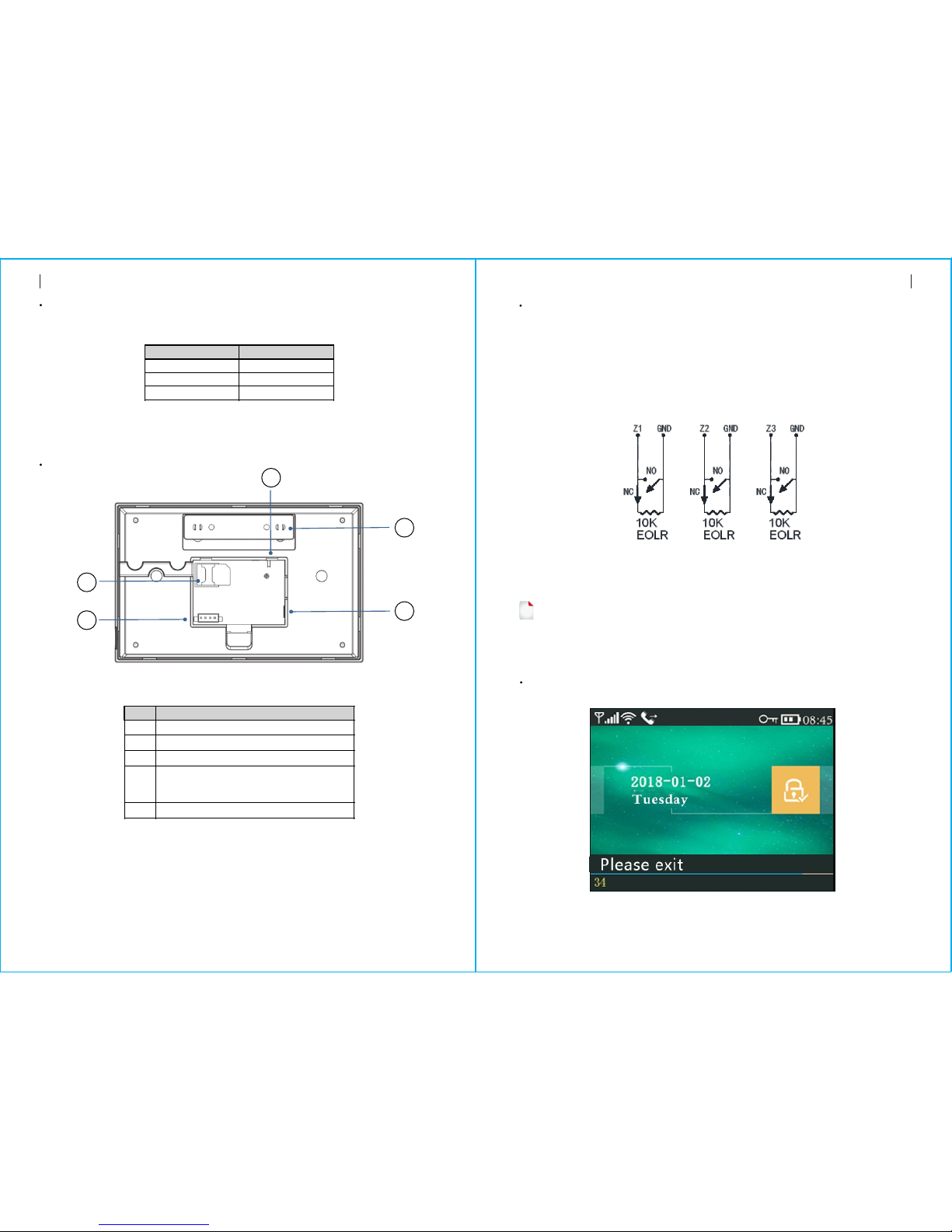
About the Panel
32
1
4
3
6
7
8
9
5
2
Index
1
2
3
4
5
6
7
8
9
Item
Display Window
Speaker
Panic Key
Away/Stay Arm
Button
Disarm Button
Menu
Buttons
Scroll Up/Function/
Scroll Down/Backspace/
Page Down Button
Cancel/Back
Button
Enter Button
Description
2.4"TFT Display screen. Displays system status
icons and information, time, zone(s) alarm
information and user menus.
Alarms and confirmation sounds.
Press to generate a Panic Alarm in case
of fire or personal emergency.
Press to arm the entire burglary system,
perimeter and interior.
Press twice to arm perimeter portion programmed
for “Stay Arm Active” of burglary system only.
Interior protection is not armed,which allows
movement within premises without causing alarm.
Press to disarm the system and to clear alarm.
Press twice to clear trouble display of accessories.
Scroll up to the desired function or menu.
Scroll down to the desired function or menu.
Return to the previous screen.
Select option or enter to the next screen.
Page Up Button
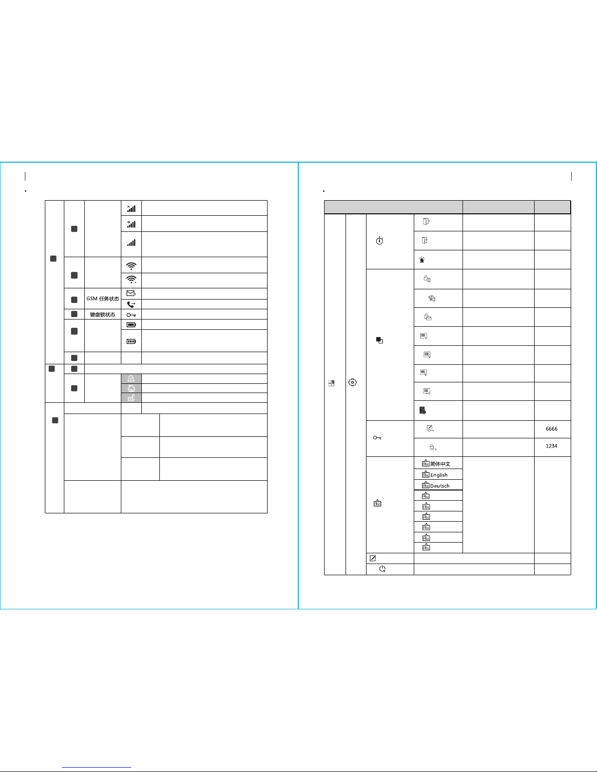
Hardwired Zone Connections
SYSTEM OVERVIEWSYSTEM OVERVIEW
54
About the Backlight Indicators of Panic Key
Wiring Overview
Zone 1、Zone 2 and Zone 3 are the EOLR supervised zones that supports both open circuit
and closed circuit devices and has a response time of 300msec . Maximum zone resistance:
11000 ohms,plus EOLR
Connect closed circuit devices in series in the high (+) side of the loop. The EOL resistor
must be connected in series with the devices, following the last device.
Connect open circuit devices in parallel across the loop. The 10000-ohm EOLR must be
connected across the loop at the last device.
Refer to the Hardwired Zones Connections diagram.
the Hardwired Zones Connections Diagram
EOLR(End of Line Resistor): If the EOLR is not at the end of the loop, the
zone will not be properly supervised, and the system may not respond
to an open circuit on the zone.
!
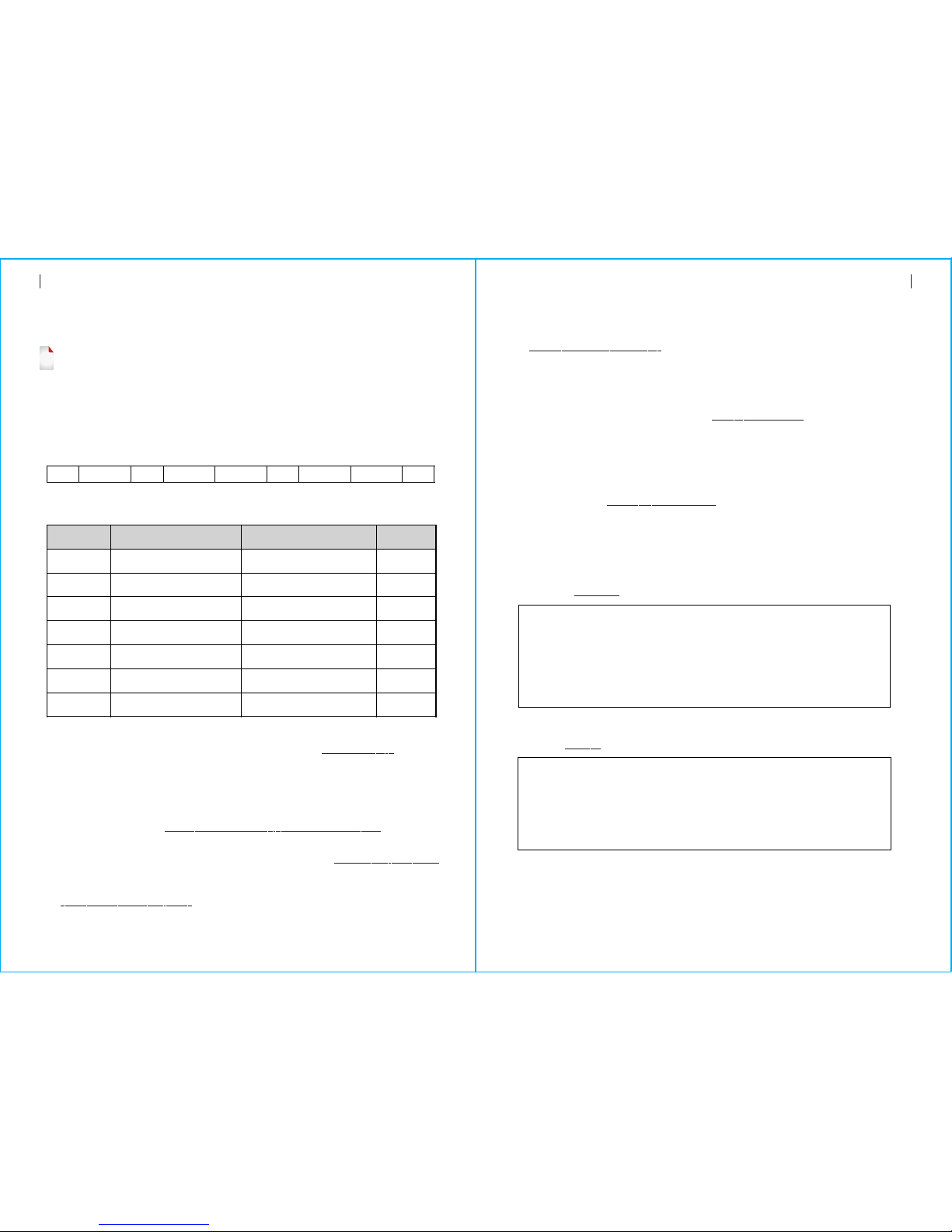
Home Screen
Index
1
2
3
4
5
Description
Power Supply Receptacle
Backup Battery Switch
SIM card Receptacle
EOLR Hardwired Zones Connections, refer
to section 2.3 and the Hardwired Zones
Connections diagram
Tamper Switch
WHAT YOU SEE WHAT IT MEANS
Blinking alternately
Pulse
Steady
System is in Alarm
System is Armed
System is Disarmed
1
2
3
4
5
About the Home Screen Display
SYSTEM OVERVIEW
4
7
11
10
9
8
6
5
3
2
1
08:45
76
SYSTEM OVERVIEW
08:45
System Status Display Area
Countdown
“Please exit”
Countdown Bar
“Synchronizing”
Countdown Bar
“Alarm” is displayed upper the red bar, and the Zone
“Alarm” is displayed in a red status bar along the red
bar. An alarm (bell) icon along with “Alarm ”is displayed
alternately with the Zone that has caused the alarm.
Sniffer Mode
You must active the wireless transmitter
before the sniffer delay expires.
Exit Delay
You now have xx seconds to leave the premises
before the exit delay expires. When the exit
delay is completed, the alarm system is armed.
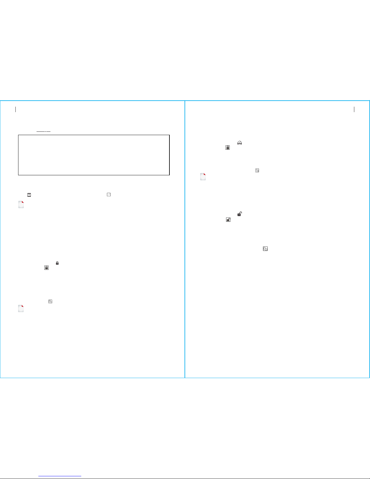
Quick View of Menu Functions
Delay Tick
Door/Window
Open Warning
Enable/Disable operation
chime
Enable/Disable entry and
exit chime
Enable/Disable Exit Alarm
Warning
Icon and Caption Description Factory
40 seconds
30 seconds
3 minutes
РУССКИЙ
Español
Polski
Italiano
Français
Português
GSM
Status
No SIM card present or SIM card faulty
Connected to server
RSSI level signal strength
Signal strength is displayed by a series of 1
to 5 bars ( weak to strong) ,and bars are gray if
not registered with cell network
Wi-Fi
Status
Indicates that the system is connected to a
WiFi source and the signal strength.
Indicates that the system is connected to the
server if dot is displayed.
SMS Sending
Calling
Keypad Locked
AC Powered
Displayed when the system has lost AC power.
The icon is red when the system’s backup
battery power is low.
Power
Status
Clock Real-time Clock
Date, time and week
Status Area
Arm/Disarm
Arm/Disarm
Status
System is Armed Away
System is Armed Stay.
System is Disarmed.
Ready Clock
Alarming
Top Status Bar
Defaults
Delay
Exit Delay
Entry Delay Used to set Entr y Delay
0~65535, unit: second
Used to set Exit Delay
0~65535, unit: second
Siren Duration Used to set Siren Duration
0~65535, unit: minute
Arm Beep Enable/Disable Arm and
Disarm Beep
Siren
Enable/Disable Alarm
Continuous Siren when
an alarm occurs
Enable
Enable
Switch
Arm SMS
Enable/Disable SMS
notification when arm
or disarm
Disable
Keypad Lock Enable/Disable Keypad
Lock Disable
Backlight Enable/Disable Keypad
Backlight Enable
Enable
Keypad Tone
Enable
Enable
Settings
Main Menu
Password
System Change System Code
4 digits
User Change User Code
4 digits
Language Language Selection English
Initialization
Reset Reset
Loading Factor y Defaults
“Please disarm”
Countdown Bar
Entry Delay
You must disarm the system before the entry
delay expires, or an alarm will occur.
(7)
(6)
(5)
(4)
(2)
(3)
(1)
(8)

SYSTEM OVERVIEW
98
SYSTEM OVERVIEW
1. :When enabled, the system will announce the system status when armed or Arm Beep
disarmed.
2. :The system will lock the keypad if no operation during 30 seconds onKeypad Lock
Home Sreen. To enable the keypad, you must enter the valid User Password.
3. :If disabled, display backlight turn off after 30 seconds if no operation on HomeBacklight
Sreen.
4. :If enabled, the system will generate a Exit Alarm Warning Door/Window Open Warnings
notification when you leaving a door or window open after the exit delay expires.
5. :used for keypad unlocking and SMS remote settings.System Password
6. :user for keypad unlocking, SMS Remote Control and Alarm text User Password
notification prefix Setting.
7. :Voice Announcement, Displaying and SMS notification will be in the selected Language
language. After selecting the desired language, the panel will reset.
8. :If the factor y default configuration is loaded, any data that has already Initialization
been programmed into the system will be changed into the Factory Default
Configuration!
Description
Set up
The First Usage
With the built-in WiFi Communications module, if your system is equipped to
report alarms and Remote Access via Mobile APP over the internet, your router must
remain powered-on at all times, and a WiFi internet connection is required.
With the built-in GSM/3G Communications module, if your system is equipped to
report alarms and Remote control via SMS or Voice Dialling, to ensure the SIM card is
installed (refer to the diagram below ) and the panel must be connected to the
GSM/3G Cellular or to the Internet.
AC Power Connections - Connect the Power Supply to the DC 5V receptacle, and push
the backup battery switch to “ON”.
Setting Phone Numbers
Up to 5 User Phone Numbers used to receive the Alarm SMS notification and Audio Alarm
Verification.
RFID Pairing, Delete or Delete All the RFID tags
Pairing a new Wireless Key, Sensor or RFID tag
Delete/Edit Delete a Wireless Key or RFID tag from the list
Edit/Delete a wireless sensor from the list
Delete All Delete all the Wireless Key, Sensors or RFID tags
Duration Used to set Record Duration
( unit: second, 1-20 is available )
Used to display the firmware and MAC address of the WiFi module,
the firmware and IMEI of the GSM module and Serial Number of panel
Enable/Disable using the WiFi
network-provided time
Enable/Disable using the cellular
network-provided time
Add
Wi-Fi Sync
2G/3G Sync
Pairing, Edit, Delete or Delete All
the wireless sensors
MAC/IP Used to display the MAC and IP
addresses of the WiFi module
reser ved
Date&Time Set the time and date
Enable
Enable
+08:00
20seconds
Null
Eol Zone
Socket
Used to set the Zone(EOLR) Name, Type
Pairing with the wireless switch
Pairing with the wireless switch
!
Phone
1 Phone
2 Phone
3 Phone
Used to set the first Phone Number, Enable
/Disable Dialling and Enable/Disable SMS
Used to set the second Phone Number, Enable
/Disable Dialling and Enable/Disable SMS
Used to set the third Phone Number, Enable
/Disable Dialling and Enable/Disable SMS
Used to set the fouth Phone Number, Enable
/Disable Dialling and Enable/Disable SMS
4 Phone
Used to set the fifth Phone Number, Enable
/Disable Dialling and Enable/Disable SMS
5 Phone
Log
Alarm Log Used to view system alarm events.
Arm Log Used to view system arm/disarm events.
Remote Pairing, Delete or Delete All the wireless keys
Detector
Used to sends a transmission signal
to the wireless siren be paired.
Siren Learn
Wi-Fi
Alarm Socket
Airlink WiFi configuration (Requires the mobile APP).
Unbind Unbind the Panel link from the server
Record Message Recording and Playback
Play Used to listen to the recorded message
Delete Used to delete the recorded message
Arm Timer Used to set a daily time to arm automatically,
and Enable/Disable automation
Disarm Timer Used to set a daily time to disarm automatically,
and Enable/Disable automation
Disarm Timer
Timer
Record
Parts
Main Menu
st
nd
rd
th
th
Version

Select: “Main Menu Phone 1 Phone, 2 Phone, 3 Phone, 4 Phone or 5
Phone”, the system displays the Phone programming screen.
Wireless Keys
Use to scroll to , then use digits keypad to enter the Phone Number (up to
18 digits).
Use to scroll to , then use to toggle between “off ”and “on”.
When “on” is selected, the Voice Dialing Alarm will be active.
Use to scroll to , then use to toggle between “off ”and “on”.
When “on” is selected, the SMS Text Notification Alarm will be active.
Press to save your new settings.
Press one button of wireless key to send a transmission signal to the panel.
As the serial number of wireless key is added to panel, “Leaning OK”will be displayed.
The system will display“Device code has been learnt”if serial number of wireless key
have been learned.
Pairing a New Wireless Key
Select ”Main Menu Parts Remote Delete”.
Use the buttons to scroll to the serial number be deleted.
Press to delete the selected serial number.
Delete
Wireless Sensors
Select ”Main Menu Parts Add”.Detector
Pairing a New Sensor
1110
The First Usage The First Usage
Select ”Main Menu Parts Remote Delete All”.
A total number of serial numbers learned is displayed.
To delete all the serial numbers, press .
Delete All
Use to scroll to , then use to scroll to the desired Zone Name.
Use to scroll to , then use to scroll to the desired Zone Mode(Type).
You must assign a Zone Type to each zone(sensor), which defines the way in which the
system responds to faults in that zone.
“ ” usually assigned to sensors or contacts on entr y and exit doors, Stay Arm Active
exterior doors and windows, perimeter. Active when armed in AWAY or STAY mode.
Use to scroll to , then use digits keypad to enter the Zone Number (0-89 are
available). The Zone Number should be unique.
Press Synchronizing” is displayed, the system goes into the sniffer mode and ,“
count down the pairing time remaining .
Active wireless sensor to send a transmission signal to the panel.
As the serial number of wireless sensor is added to panel, “Leaning OK”will be
displayed.
The system will display“Device code has been learnt”if serial number of wireless
sensor have been learned, and the Zone Name/Mode/Number will be refreshed.
Select ”Main Menu Parts Edit”.Detector
Use the buttons to scroll to the serial number be edited.
To edit the Name/Mode/Number of displayed zone, press .
To delete the selected serial number, press .
Edit/Delete
Select ”Main Menu Parts ”.Detector Delete All
A total number of serial numbers learned is displayed.
To delete all the serial numbers, press .
Delete All
RFID Tags
Select ”Main Menu Parts RFID Add”.
Pairing a New RFID Tag
Select ”Main Menu Parts RFID Delete”.
Use the buttons to scroll to the serial number be deleted.
Press to delete the selected serial number.
Delete
Select ”Main Menu Parts Remote Add”.
“Synchronizing” is displayed, the system goes into the sniffer mode and count down
the pairing time remaining .
“” usually assigned to a interior area (i.e.: foyer, lobby,or room). Out Arm Active
Bypassed automatically when armed in STAY mode.
“” usually assigned to a zone containing an Emergency Button, Smoke 24 Hours Active
Sensor, CO, Water Leakage and Gas Sensors.
To used as doorbell, select “ ”.Doorbell
To disable the zone, select “ ”.Close
“Synchronizing” is displayed, the system goes into the sniffer mode and count down the
pairing time remaining .
Put the tag close to the RFID area of panel.
As the serial number of tag is added to panel, “Leaning OK”will be displayed.
The system will display“Device code has been learnt”if serial number of tag have been
learned..
Select ”Main Menu Parts RFID Delete All”.
A total number of serial numbers learned is displayed.。
To delete all the serial numbers, press
Delete All
st nd rd th th

Select “Main Menu Timer Arm Timer ”, the system displays the Arm Timer
programming screen.
Meassage Recording
Message Recording and Playback
Your system can Record/Playback/Delete a brief message(up to 20 seconds)
that can be played back later. The message will be played to the remote when
a alarm call is connected.
Select “Main Menu Record Record”,the system displays the Record screen.
Ready to record when “Recording”is displayed in the title box and the system
display will count down the recording time remaining.
Speak into the microphone and the recording automatically stops after the time
expires.
The system plays back the message automatically.
Press button to save the message.
Arm/Disarm Automatically
The feature can be used to program the system to arm or disarm the system automatically
at a daily time.
Arm Schedule
Use to scroll to , then use digits keypad to enter the Daily Arm time (in 24-hr).
Use to scroll to , then use to select“on”.
Press to save your new settings.
Disarm Schedule
The First Usage The First Usage
Operating the Wireless Strobe Siren to go into the Sniffer mode( refer to user guide of
strobe siren ) .
Select “Main Menu Parts Siren Learn”.The panel displays ” Learn Signal Sent”
and sends a transmission signal to the Strobe Siren.
The Strobe Siren gives a successful indication.
Pairing with Wireless Siren
13
12
Alarm Syncing with Wireless Switch
Select “Main Menu Parts Alarm Socket”, the system displays the Alarm Socket
pairing screen.
Operating the Wireless Switch to go into the Sniffer mode( refer to user guide of
wireless switch ) .
Press the “on” button and the “off ”button in turn , The panel displays
” Learn Signal Sent” and sends a transmission signal twice to the Wireless Switch.
The Wireless Switch gives a successful indication.
To test if pairing ok, press “on”and “off”to check if the wireless can be opened and
closed.
When a sound alarm occurs, the Wireless Switch will be opened until the system is
disarmed or alarm sounder timeout occurs.
Pairing with Wireless Switch
Home Automation (If equipped)
!
You can open or close the wireless switch via Mobile APP.
Pairing with Wireless Switch
To pair with the wireless switch (up to 8 switches), refer to the previous section
"Pairing with Wireless Switch”.To test if pairing ok, press “on”and “off”to check if
the wireless can be opened and closed.
Select “Main Menu Timer Disarm Timer”, the system displays the Disarm Timer
programming screen.
!
!
Use to scroll to , then use digits keypad to enter the Daily Disarm time (in 24-hr).
Use to scroll to , then use to select“on”.
Press to save your new settings.
How to set the parameters via SMS
Mobile APP
Scan the QR codes via a smart phone to download the app.
15
14
Mobile APP Remote SMS
!
The Smart Security System app will guide you to connect the panel to
the WiFi network and the internet.
To set the parameters via SMS, editing the setting text message as below,
then sends it to the SIM number installed in the panel. Your mobile will
received an acknowledgement SMS if setting ok.
System Command1 Parameter1 Command2 Parameter2
Note: The command must be 2 digits( e.g.,01,90,etc. ), and the header,
separator and ending character must be‘*’.。
Note:
The exmples uses the default system password 6666.
1、T he Phone Number setting format of remote text message: xxxxxxxxxx,A,B
In this sting, “xxxxxxxxxxx” is the phone number( up to 18 digits ), “A” used to
Enable(1) or Disable(0) the Alarm Voice Dialling and “B” used to Enable(1) or
Disable(0)the Alarm SMS notification.
For example:
To set the 1st Phone Number as “13912345678” and enable the SMS notification only,
and to set 2nd Phone Number as “075512345678” and enable the Voice Dialling only,
then the remote SMS is *6666*5113912345678,0,1*52075512345678,1,0*.
2、 The server IP address and Port used for connection to the alarm monitoring company.
The server IP and Port setting format of remote text message: aaa,bbb,ccc,ddd,xxxxx
In this string, “aaa,bbb,ccc,ddd” is the IP and “xxxxx” is Port.
For example:
To set the IP and Port as “116.62.42.223:2001”, then the remote SMS is
*6666*90116,62,42,223,2001*.
The alarm SMS notification prefix
The panel can be named after a customized text via remote SMS. The name is used for the
alarm SMS notification prefix.
The alarm notification prefix setting format: 1234@XXX building.
How to set the customized Zone Name
You can set a customized name for each zone via remote SMS. The name is used to indentify
which zone alarm occurs in the SMS notification.
Remote SMS format: 1234@XX@Down Stairs
In this string, “1234”is the User Password , two ”@”are command flags, “XX”is the
Zone Number(from 00 to 89) and “Down Stairs” is the customized text.。
Get the settings via remote SMS
Quer y the system settings
Format is *6666*62*, and the panel echoes as follow.
SYSTEM set:
SN: Serial Number of the panel
LANGUAGE: Language
ENGINEER PASSWORD: System Password
USER PASSWORD: User Password
GSM CSQ: GSM RSSI
WIFI RSSI: Wifi RSSI
Query the second page of system settings
Format is *6666*90*, and the panel echoes as follow.
SYSTEM set2:
APN: GPRS Access Point Name
GPRS IP: Server IP address and Port
NTP: reserved
TIME ZONE: reserved
SERVER: reserved
*
** *
Command Function Description Factory
Defaults
the server IP address and
Port
the GPRS APN
refer to note 1
refer to note 1
refer to note 1
refer to note 1
refer to note 1
Only used for connection to
server, refer to note 2
Only used for GPRS network,
refer to note 3
51
52
53
54
55
90
92
Null
Null
Null
Null
Null
Null
CMNET
Remote SMS
Password
3、S etting the operator Access Point Name
For example:
To set the APN as “internet.beeline.kz”, then the remote SMS is
*6666*92 internet.beeline.kz*.
In this string, “1234”is the User Password ,”@”is a command flag and “XXX building ”
is the customized text.
1 Phone Number
st
2 Phone Number
nd
3 Phone Number
rd
4 Phone Number
th
5 Phone Number
th
17
16
Remote SMS SECURING THE PREMISES
Query the Phone Number Settings
Format is *6666*51*, and the panel echoes as follow.
1: The 1st Phone Number, Voice Dialling and SMS switches
2: The 2nd Phone Number, Voice Dialling and SMS switches
3: The 3rd Phone Number, Voice Dialling and SMS switches
4: The 4th Phone Number, Voice Dialling and SMS switches
5: The 5th Phone Number, Voice Dialling and SMS switches
REDIAL COUNTER: Redial Counter for Voice Dialling
How to make a call via the panel
On the home screen, you can make a call via the digit keypad.
Press to view the list of dialled number, then press to redial it.
The call will be cancelled if GSM network is not registered, the system is armed or in
voice alarming.
!
SECURING THE PREMISES
Arming the System
Arming in Stay Mode
This mode is used when you are staying home.
To arm the system in stay mode, you can operate as below:
Disarming the System
PHONE set:
To arm the system, you can operate as below:
By Wireless Key: Press key.
By Panel: Press. button when home screen is displayed.
By RFID tag: Put the RFID tag close to the RFID area when system is disarmed.
: Press the Arm icon, then select the Exit Delay.By APP
By remote SMS: Send a message 1234#1 (“1234”is User Password) to the panel, then an
acknowledgement SMS will be returned if armed.
The system will announce “System Armed”. Home Screen will displays the “Armed”
icon and the countdown bar. You must leave the premises before the Exit Delay expires.
If the“Arm SMS” is enabled, you will receive a SMS notification.
All burglary zones, interior & perimeter, are armed.
By Wireless Key: Press key.
By Panel: Press button twice when home screen is displayed.
By APP: Press the Stay Arm icon.
By remote SMS: Send a message 1234#3 (“1234”is User Password) to the panel, then an
acknowledgement SMS will be returned if armed.
The system will announce “System Armed”. Home Screen will displays the “Stay
Armed”icon. If the “Arm SMS” is enabled, you will receive a SMS notification.
Perimeter burglary zones ( Zone Type programmed as Stay Arm Active ), such as
windows and doors are armed.
!
To disarm the system ,to silence alarm ,to clear trouble displays and to cancel the alarm
that is in progress , you can operate as below:
By Wireless Key: Press key.
By Panel: Press button when home screen is displayed.
By RFID tag: Put the RFID tag close to the RFID area when system is armed.
: Press the Disarm icon.By APP
By remote SMS: Send a message 1234#2 (“1234”is User Password) to the panel,
then an acknowledgement SMS will be returned if armed.
The system will announce “System Disarmed”. Home Screen will displays the
“Disarmed”icon. If the “Arm SMS” is enabled, you will receive a SMS
notification.
!
SOS
To manually active panic function, you can operate as below:
By Wireless Key: Press SOS key.
By Panel: Press SOS key on the panel.
: Press the SOS icon.By APP
Home screen displays “Panic Alarm”. An Panic Alarm will be generated.
An Panic Alarm send an text notification to your mobile ,and sounds a loud,steady alarm
at your panel.

Specifications
19
18
SECURING THE PREMISES Specifications
Multi-Mode Alarm Feature
: If the building and/or neighbourhood has lost electrical power, the Loss of AC Power
system will continue to operate on battery forseveral hours.
SYSTEM TROUBLES:
SMS Notification Feature
When an alarm or system trouble occurs, a SMS notification will be sent to the Phone
Number that have been programmed in your system.
Two-Way Voice Feature
When an alarm occurs, the system will dial to your Phone Number that have been
programmed in your system. After the call is connected, you can hear the voice
message that have been recorded and what the alarm occurs, then system will
announce “Press 1 to arm, press 2 to disarm, press 3 to monitor, press 4 to talk”.
Press 3 or 4 to listen the violated premises and voice dialog between an operator
and an individual at the premises. If a false alarm is ensured, press 1 to cancel the
alarm that is in progress.
Voice Dialog
The Phone Programmed Call the Panel
When the phone that have been programmed in the system call the panel, two-way voice
is connected automatically. Allows operator to listen, talk to or conduct two-way
conversations with individuals on the premises.
: Plug-in Power Supply, micro USB 110/220VAC to 5VDC, Primary Power
1A output
: 3.7V/500mAh Rechargeable Lithium Polymer Battery Backup battery
: <150mA@normalConsumption
: <300mASiren Output
: 315/433/868/915Mhz (optional)Radio Frequency
: eV1527RF code
: 850/900/1800/1900MHzGSM
: IEEE802.11b/g/nWi-Fi
: 0~55℃Operation Temperature
: “Low Batter y” is displayed when the system’s backup battery System Low Battery
power is low.
: Each wireless sensor in your system has an internal battery. Sensor Low Battery
The system detects low batter y conditions in wireless sensors, and displays a
“Sensor Low Battery” message on the home screen, means that batter y replacement
in the indicated sensor(s) is due within 7 days.
.AC Power Normal
: when a cover tamper has been detected to generate a Tamper Alarm.Tamper
Table of contents
Popular Security System manuals by other brands

NAPCO
NAPCO Commercial GEMC brochure

König Electronic
König Electronic SEC-ALARM200 manual

Nortek Security & Control
Nortek Security & Control Linear BluePass 820-00001 installation guide

Teletek electronics
Teletek electronics CA824 installation manual

E2S
E2S STExB2LD2 instruction manual

FIBER SENSYS
FIBER SENSYS FD322 Product training


