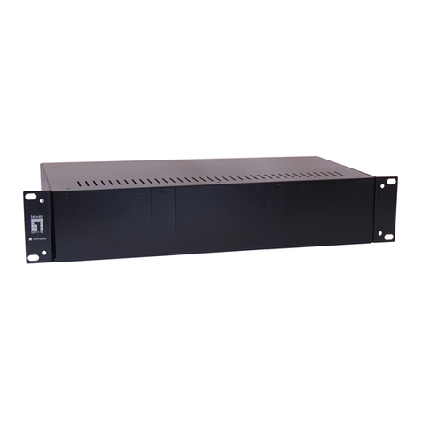
Telenetics RM16M - Versatile Rack Mounting Chassis Operating instructions

RM16M DCV-R/ RM16M ACV-R
Installation and Operation Guide
TEL-6200508506004 Rev. A

The products and programs described in this Installation and
Operation Guide are licensed products of Telenetics Corporation. This
Installation and Operation Guide contains proprietary information
protected by copyright, and this Installation and Operation Guide and
all accompanying hardware and documentation are copyrighted.
Telenetics Corporation does not warrant that the hardware will work
properly in all environments and applications, and makes no warranty
and representation, either implied or expressed, with respect to the
quality, performance, merchantability, or fitness for a particular
purpose.
Information in this Installation and Operation Guide is subject to
change without notice and does not represent a commitment on the
part of Telenetics Corporation. Telenetics Corporation assumes no
responsibility for any inaccuracies that may be contained in this
Installation and Operation Guide.
Telenetics Corporation makes no commitment to update or keep
current the information in this Installation and Operation Guide, and
reserves the right to make changes to this Installation and Operation
Guide and/or product without notice.
No part of this manual may be reproducedor transmitted in any form
or by any means, electronic or mechanical, including photocopying,
recording, or information storage and retrieval systems, for any
purpose other than the purchaser's personal use, without the express
written permission of Telenetics Corporation.
Copyright 2002 Telenetics Corporation.

Page iii
FCC Requirements
This equipment complies with FCC Rules, Part 68. Located on the
equipment is the FCC Registration Number and Ringer Equivalence
Number (REN). You must provide this information to the telephone
company if requested.
The Registration number and REN will be inscribed on the printed
circuit board on insert cards or on a label attached to either the chassis
bottom or metal end plate on standalone or rack models. In any case,
the FCC requires these numbers to be prominently displayed on an
outside surface of the equipment.
The REN is used to determine the number of devices you may legally
connect to your telephone line. In most areas, the sum of the REN of
all devices connected to one line must not exceed five (5.0). You
should contact your telephone company to determine the maximum
REN for your calling area.
The telephone company may change technical operations or
procedures affecting your equipment. You will be notified of changes
in advance to give you ample time to maintain uninterrupted telephone
service.
contact: ARC Electronics 800-926-0226
The telephone company may ask that you disconnect this equipment
from the network until the problem has been resolved. If your
equipment continues to disrupt the network, the telephone company
may temporarily disconnect service. If this occurs, you will be
informed of your right to file a complaint with the FCC.
This equipment may not be used on coin services provided by the
telephone company. Connection to party lines is subject to state
tariffs.
WARNING: This equipment uses, generates, and can radiate radio-

Page iv
frequency energy, interfering with radio communications, if not
installed and used according to the instruction manual. It has been
tested and complies with the limits for a Class A computer device,
according to FCC Rules, Part 15. Operation of this equipment in a
residential area may cause interference. If it does, you must correct the
cause of the interference.
Changes or modifications to this unit are not expressly approved by
the party responsible for compliance could void the user’s authority to
operate the equipment.

Page v
Contents
CHAPTER 1 INTRODUCTION................................................................7
OVERVIEW..................................................................................................7
BACK PANEL INTERFACE CONNECTORS ..................................................9
LOCALVIEW DC SHELF MODEL..............................................................11
CONTACT INFORMATION.........................................................................12
CHAPTER 2 INSTALLATION..............................................................13
UNPACKING AND INSPECTING THE EQUIPMENT.....................................13
SITE PREPARATION..................................................................................13
INSTALLATION PROCEDURES ..................................................................15
Required Tools and Equipment....................................................15
Mechanical Assembly.....................................................................15
ELECTRICAL INSTALLATION ...................................................................16
AC Power (RM16M ACV-R Data Shelf)......................................16
DC Power (RM16M DCV-R Data Shelf) .....................................16
Digital EIA-232 Interface...............................................................18
TELEPHONE LINE INTERFACES................................................................19
Modular Jack Connectors.............................................................19
Optional Backplanes for Dial Backup Connections................19
INSTALLING AND REMOVING POWER MODULES....................................20
AC Power Module...........................................................................20
DC Power Module...........................................................................22
Installing Power Modules..............................................................22
Removing Power Modules.............................................................23
INSTALLING AND REMOVING PC CARDS ................................................23
Removing PC Cards........................................................................24
DIGITAL INTERFACE BACKPLANE INSTALLATION.................................25
CHAPTER 3 OPERATION.....................................................................29
TEST MODES ...........................................................................................29
FRONT PANEL INDICATORS.....................................................................29
SPECIAL ASSEMBLIES .............................................................................31

Contents
Page vi
CHAPTER 4 MAINTENANCE................................................................33
PC CARDS ................................................................................................33
POWER MODULE .....................................................................................33
APPENDIX A SPECIFICATIONS .........................................................35
APPENDIX B 24 VOLT INPUT DATA SHELF...................................37
24 VOLT SHELF SPECIFICATIONS ...........................................................37
APPENDIX C DIGITAL INTERFACE DESCRIPTIONS...................39
APPENDIX D TELEPHONELINE CABLES........................................43
TECHNICAL SUPPORT..............................................................................48
RETURN MERCHANDISE AUTHORIZATION (RMA) PROCEDURE .........48

Page 7
Chapter 1
Introduction
he Telenetics RM16MUniversal Data Shelf™ is a heavy-gauge
steel-plated modem rack chassis. It measures 7 inches high and
10.75 inches deep, and mounts in a standard 19-or 23-inch rack.
The Data Shelf comes in two versions: AC (RM16M ACV-R) and DC
(RM16M DCV-R). This Guide covers both versions.
Overview
The Telenetics RM16M Universal Data Shelf has slots that accept 16:
vModems
vMultiplexers
vDigital Data Service (DDS) units
vDial backup units
vAutomatic calling units
All of these devices are plug-in printed circuit (PC) cards that slide
into the front of the Data Shelf. The cards can be mixed in any way
within the Data Shelf. Each card has been independently tested and
meets Part 68, FCC rules and regulations.
Power, Data Terminal Equipment (DTE), and communication-line
connections are made at the back panel of the Data Shelf (see “Back
Panel Interface Connectors” on page 9). This allows PC cards to be
installed or replaced, without disturbing the cable connections at the
back
The AC version of the Data Shelf accepts a single power module that
occupies two slots, while the DC version accepts two power modules
that occupy one slot each. The power modules power all the PC cards
T

Installation
Page 8
in the Data Shelf, converting user-supplied 48 volt DC input to + 15
Vdc, −15 Vdc, and +8.5 Vdc outputs for distribution to the PC cards.
Regulators on the PC cards convert the plus and minus 15 Vdc to plus
and minus 12 Vdc and + 8.5 Vdc to +5 Vdc.
NOTE: If two power modules are installed in the DC version of the
Data Shelf, one powers the Data Shelf while the other acts as a
redundant power source.
Figure 1-1 shows an example of the location and orientation of the
modem cards and power module. For convenience, the front panel of
the Data Shelf is hinged to allow easy access to the modem cards and
power module(s) without disturbing the DTE and communication-line
connections at the back of the Data Shelf.
Figure 1-1. Data Shelf Example

Page 9
Back Panel Interface Connectors
All DTE, Telco and power connections are made at the back panel of
the Data Shelf.
The DTE connectors can be:
vIndividual 25-pin connectors one for each PC card (standard)
vTwo 50-pin mass termination connectors (optional)
vWire-wrap pins (optional)
The Telco connectors can be:
vIndividual 8-pin modular jacksone for each PC card (standard)
vTwo 50-pin termination connectors (optional)
vWire-wrap pins (optional)
The telephone-line connectors are identified by the telephone
company Universal Service Ordering Code (USOC) and must be
specified when ordering standard jack arrangements from Telenetics.
The various jack arrangements ensure that the signal level received at
the telephone company central office does not exceed–12 dBm. The
Data Shelf has been registered with the FCC per the requirements of
Part 68 of the FCC rules for:
1. Programmable Mode the local telephone company will install a
resistor internal to the jack (USOC RJ455 or RJ41S).
2. Permissive Mode the individual modem cards are
preprogrammed for a maximum transmit level of –9 dBm (USOC
RJ11C or RJ16X).
Figures 1-3 through 1-5 show examples of Data Shelf back panels.
NOTE: For more information about the power connections, refer
to “Electrical Installation” on page 16.

Installation
Page 10
Figure 1-3. Examples of Back Panels with 25-pin DTE Connectors
and 8-pin Modular Telco Jacks
Figure 1-4. Example of Back Panel with 25-pin EIA DTE Connectors
and Mass Termination Telco Connectors

Page 11
Figure 1-5. Example of Back Panel with Mass Termination
Connectors for DTE and Telco Connections
LocalView DC Shelf Model
The LocalView DC shelf is a special model of the DC version of the
Data Shelf that provides modem system network management.
Figure 1-6 shows the back panel of the LocalView Data Shelf.
LocalView allows devices in a Shelf to be controlled or interrogated
through shared input/output devices.
The system includes a controller that resides in slot 16 of the Shelf and
a modified backplane that uses unused pins on the power connector
to pass data, address, and control information between the controller
and device cards.
LocalView allows a single controller to address up to five shelves.
With these shelves fully populated, a total of 79 device cards can be
addressed either from the LCD on the front of the controller or through
an RS232 port on the rear of the controller. For information, refer to the
LocalView controller card manual.

Installation
Page 12
Figure 1-6. Back Panel of LocalView Data Shelf (DC Version only)
Contact Information
For more information about Telenetics Universal Data Shelves, or
other Telenetics solutions, contact us using any of the following
methods.
Voice Calls
We welcome your calls at(949) 455-4000 Monday
through Friday, from 8:00 am to 5:00 pm Pacific Time.
Fax Number
You can also send your requests for information to our
24-hour fax number: (949) 455-4010.
E-mail
If you prefer, you can send information requests toour
24-hour e-mail address: [email protected].

Page 13
Website
Our website contains valuable information about our
products. We encourage you to visit us online at
www.telenetics.com.
Chapter 2
Installation
his chapter describes how to install the Data Shelf.
Unpacking and Inspecting the
Equipment
Unpack the equipment and compare the contents to the packing list.
Inspect the equipment for any damage that may have occurred in
shipment. If you see any damage or if items are missing, contact
Telenetics. Keep the shipping container and packing material for
future shipment.
Site Preparation
When selecting a location to install the Data Shelf, choose a site that:
vIs clean, well lit, and free from extremes of temperature, humidity,
appreciable shock, and vibration.
vIs within seven feet of a power source that can furnish 48 ±4 Vdc
at 3.5 amps.
vIs within 50 feet of the associated data terminal.
vProvides at least 36 inches of clearance at the front for operating
and maintenance accessibility.
T

Installation
Page 14
vProvides at least 4 inches at the back of the enclosure for interface
cable clearance and unobstructed airflow.
Side and top clearances for rack-mounted equipment are dictated by
the rack-cabinet provisions, but should allow a free flow of cooling air
(Figure 2-1).
Figure 2-1. Data Shelf Cabinet

Page 15
Installation Procedures
Service personnel should be familiar with the complete installation
procedure before installing the shelf.
Required Tools and Equipment
Special tools or test equipment are not required for installation.
CAUTION: To prevent damage to enclosure components from
overheating, ensure clearances of 1 ¾-inch top and bottom
between mounted enclosures. Make adequate provision for cool
air circulation and exhaust of warm air, such as air intake louvers
in the bottom panel of the Data Shelf cabinet and an adequate
CFM exhaust fan in the top panel of the Data Shelf cabinet.
Mechanical Assembly
The Data Shelf mounts into a standard 19-inch cabinet and requires 7
inches of vertical panel space (see Figure 2-2).
The 19-inch Data Shelf also fits into a 23-inch cabinet. This installation
requires the rack-mounting brackets to be removed and reinstalled in
the reversed position, so the wider tabs are used for mounting to the
cabinet (see Figure 2-3).
Figure 2-2. Mounting Dimensions
Figure 2-3. Mounting Dimensions for a 23-inch Rack

Installation
Page 16
Electrical Installation
All power connections are made at the back panel of the Data Shelf.
AC Power (RM16M ACV-R Data Shelf)
Power for the AC version of the Data Shelf (RM16M ACV-R) is
supplied to the power modules through a separate AC power cord.
The power cord is fastened to the back panel with a cable clamp to
prevent it from becoming unattached.
After the power module is installed and fastened to the rear panel,
insert the power cord into the power module socket on the back of the
Data Shelf.
To apply power to the module plug the opposite end of the power
cord into a standard 115VAC grounded wall socket.
DC Power (RM16M DCV-R Data Shelf)
Power for the DC version of the Power Shelf (RM16M DCV-R) is
provided by an incoming power source that connects to TS1, TS2, or
both on the back of the Data Panel (see Figure 2-4). Facing the front of
the Data Shelf, TS1 supplies the power module on the left and TS2
supplies power to the power module on the right.
One power module is sufficient to power all 16 slots. If one power
source is available, it can connect to either terminal strip (TS1 or TS2)
on the back of the Data Shelf, with shunt bars installed to connect
power to the opposite strip (see Figure 2-5). The bars should always
be installed if only one power source is used and must be removed if
two power sources are used.
TS1 and TS2 alarms and chassis ground are connected internally. An
alarm condition exists on the alarm circuit when any operating or
supply voltage is lost on either power supply. By observing which
front panel power LED is out, you can identify the faulty power
supply.

Page 17
Figure 2-4. Power Terminals
Figure 2-5. Example of a Single Power Source Installation

Installation
Page 18
Digital EIA-232 Interface
The 16 EIA-232C or D digital input connectors are labeled and shown
in Figure 2-2. These connectors are either Cannon or Cinch 25-pin D
series, as defined in EIA-232. For a description of the active pin
connectors, refer to Appendix D on page 39.
Table 2-1 shows the EIA-232 levels from the modem.
NOTE: Some modems may not use all the functions listed in
Tables 2-1 and 2-2.
Table 2-1. Modem EIA Levels
Received data mark: –5 to –15 V
Received data space: +5 to +15V
Control signal OFF level: –5 to –15V
Control signal ON level: +5 to +15V
Table 2-2 shows the expected levels on all inputs.
Table 2-2. Expected Levels on All Inputs
Mark: –3 to –25 V
Space: +3 to +25V
Controls OFF: –3 to –25V
Controls ON: +3 to +25V

Page 19
Telephone Line Interfaces
The Data Shelf is FCC certified for connection to the dial-up Public
Switched Telephone Network (PSTN). The following sections describe
the standard and optional ways for connecting to the communications
line.
Modular Jack Connectors
The standard Data Shelf back panel has 16 8-pin modular jacks, one for
each modem. These jacks provide the interface for connecting
individual modems to the telephone line. Each 8-pin jack has contacts
that are used in various combinations depending on the type of
service installed. Leased-line modems, by comparison, have four
contacts: a transmit pair and a receive pair.
For a description of the modular jack functions, refer to Table E-1 in
Appendix E on page 43.
Optional Backplanes for Dial Backup Connections
Two optional Data Shelf backplanes are available for use with dial
backup modems. These backplanes provide either modular or mass
termination jacks for both dial-up and leased line telephone line
connections. Figure 1-4 on page 10 and Figure 1-5 on page 11 show
examples of these backplanes.
Modems with dial backup capability can switch to a dial-up line if the
leased line fails. For this reason both the TELSET/LL and TELCO
connections must be made. If the option is not used, connect the
modem to the appropriate service, either leased line or dial-up. If
standard modems (no dial backup capability) are installed they are
limited to connection to the TELCO only.
For a description of the modular jack functions, refer to Table E-1 in
Appendix E on page 43.
NOTE: Telco jack pin functions are identical for both standard
and dial backup modems. Similarly, DTE connectors are the

Installation
Page 20
same as for standard modems.
Installing and Removing Power Modules
Power modules generate power that is bused to the 16 modem edge
connectors on the recessed power bus. Power modules are available in
AC and DC versions.
AC Power Module
The AC power module is a 2-slot module designed for the RM16M
ACV-R Data Shelf. The RM16M ACV-R Data Shelf can hold a
maximum of one AC power module.
The AC power module consists of:
vTwo transformers (one for slots 1 through 8 and the other for
slots 9 through 16)
vTwo push-button circuit breaker switches on the front panel
vA red 3.5 Amp light on the front panel
vA 115 or 230 VAC connector on the back of the module
Table 2-3 lists the connector pin functions on the AC power module.
Table 2-3. Power Connector Pin Functions
Pin Contact Function
1 and A
2 and B
Plus and minus 12 Volt
Winding
3 and C 12 Volt Common
4 and D
5 and E
5 Volt Winding
6 and F Chassis Ground
This manual suits for next models
2
Table of contents
Popular Chassis manuals by other brands
JetStor
JetStor SAS 724HS 10G Series Quick installation guide

Overland Storage
Overland Storage NEO 4000e Remove & Replace Instructions
Netstor
Netstor NR340A-IP2 Quick installation guide
Overland Storage
Overland Storage SnapServer DX2 Replacement instructions
Svive
Svive LUNA S100 manual
Advantech
Advantech IPC-7132 user manual
