Telestream Wirecast Gear 210 User manual
User Guide
Wirecast Gear User Guide 1.0
The latest version of the Wirecast Gear User Guide is available at:
http://www.telestream.net/pdfs/user-guides/Wirecast-Gear-User-Guide.pdf
Wirecast Gear User Guide | 229961
September 2017


3
Contents
Preface 7
Introduction to
WC Gear 9
Introduction 9
Overview 9
Wirecast Gear Models 9
Features 10
Unpacking Wirecast Gear 10
Registering Wirecast Gear 11
Specifications 11
Operating System Specifications 11
Software Specifications 11
Hardware Specifications 12
WC Gear
Panels 13
Introduction 13
Front Panel 14
Rear Panel 15
Rear Panel Differences 16
Installation of
WC Gear 19
Introduction 19
Physical Mounting 19
Wireless Connections 19

Contents
4
Using
WC Gear 23
Introduction 23
Getting Started 23
First Time Boot 23
Configuring the I/O Ports 26
Introduction 26
Setup 26
Reference Input 30
Troubleshooting and
Updating WC Gear 31
Introduction 31
General 31
Drive Initialization 32
Windows Update Issues 33
Support for
WC Gear 35
Introduction 35
Obtaining Support | Information | Assistance 35
Return Merchandise Authorization (RMA) Procedure 37
Support and RMA Process 37
Regulatory Compliance Statements 39
Introduction 39
Regulatory Compliance Statements for the Wirecast Gear models 110, 210, 220 and
230 39
Local Restrictions on 802.11a, 802.11b, 802.11g and 802.11n Radio Usage Caution
39
Federal Communications Commission (FCC) Compliance Notices 40
Class B Interference Statement 40
FCC Caution 40
RF Radiation Exposure & Hazard Statement 41
Non-Modification Statement 41
Unlicensed National Information Infrastructure (U-NII) Bands Operation Statement
41
Dynamic Frequency Selection (DFS) 41
Canadian ICES Statements 42
RF Radiation Exposure & Hazard Statement 42
Exposition aux radiations RF & Mention de danger 42
Deployment Statement 43
Déclaration de déploiement 43
Operation in the Frequency Bands 5470-5725 MHz and 5725-5850 MHz 43

Contents 5
Fonctionnement dans les bandes de fréquence 5470-5725 MHz et 5725-5850 MHz
43
European Union and European Fair Trade Association Regulatory Compliance 43
Declaration of Conformity 44
Warning! 44
Achtung! 44
Attention! 45
National Restrictions 45
Indoor Operation 45
Antenna 45
Power Level Control 45
Operating Frequency 45
Warning and Caution Messages 45
Before operation please read the following: 46

Contents
6

7
Preface
Copyrights and Trademark Notices
Copyright 2017 Telestream, LLC. All rights reserved. No part of this publication may be
reproduced, transmitted, transcribed, altered, or translated into any languages without
written permission of Telestream, LLC. Information and specifications in this document
are subject to change without notice and do not represent a commitment on the part
of Telestream.
Limited Warranty and Disclaimers
Telestream, LLC (the Company) warrants to the original registered end user that the
product will perform as stated below for a period of one (1) year from the date of
shipment from factory, unless the customer has purchased additional warranty periods.
The Product hardware components, including equipment supplied but not
manufactured by the Company but NOT including any third party equipment that has
been substituted by the Distributor for such equipment (the "Hardware"), will be free
from defects in materials and workmanship under normal operating conditions and
use.
Warranty Remedies
Your sole remedies under this limited warranty are as follows:
The Company will either repair or replace (at its option) any defective Hardware
component or part with new or fully functioning hardware components.
Components may not be necessarily the same, but will be of equivalent operation and
quality.
Software Updates
Except as may be provided in a separate agreement between Telestream and You, if
any, Telestream is under no obligation to maintain or support the Software and

Preface
8
Telestream has no obligation to furnish you with any further assistance, technical
support, documentation, software, update, upgrades, or information of any nature or
kind.
Note: Wirecast Gear includes 90 days of complimentary support on both hardware
and software.
Restrictions and Conditions of Limited Warranty
This Limited Warranty will be void and of no force and effect if (i) Product Hardware or
Software Media, or any part thereof, is damaged due to abuse, misuse, alteration,
neglect, or shipping, or as a result of service or modification by a party other than the
Company, or (ii) Software is modified without the written consent of the Company.
Limitations of Warranties
THE EXPRESS WARRANTIES SET FORTH IN THIS AGREEMENT ARE IN LIEU OF ALL OTHER
WARRANTIES, EXPRESS OR IMPLIED, INCLUDING, WITHOUT LIMITATION, ANY
WARRANTIES OF MERCHANTABILITY OR FITNESS FOR A PARTICULAR PURPOSE. No oral
or written information or advice given by the Company, its distributors, dealers or
agents, shall increase the scope of this Limited Warranty or create any new warranties.
Geographical Limitation of Warranty—This limited warranty is valid only within the
country in which the Product is purchased/licensed.
Limitations on Remedies—YOUR EXCLUSIVE REMEDIES, AND THE ENTIRE LIABILITY OF
TELESTREAM, LLC WITH RESPECT TO THE PRODUCT, SHALL BE AS STATED IN THIS
LIMITED WARRANTY. Your sole and exclusive remedy for any and all breaches of any
Limited Warranty by the Company shall be the recovery of reasonable damages which,
in the aggregate, shall not exceed the total amount of the combined license fee and
purchase price paid by you for the Product.
Damages
TELESTREAM, LLC SHALL NOT BE LIABLE TO YOU FOR ANY DAMAGES, INCLUDING ANY
LOST PROFITS, LOST SAVINGS, OR OTHER INCIDENTAL OR CONSEQUENTIAL DAMAGES
ARISING OUT OF YOUR USE OR INABILITY TO USE THE PRODUCT, OR THE BREACH OF
ANY EXPRESS OR IMPLIED WARRANTY, EVEN IF THE COMPANY HAS BEEN ADVISED OF
THE POSSIBILITY OF THOSE DAMAGES, OR ANY REMEDY PROVIDED FAILS OF ITS
ESSENTIAL PURPOSE.
Further information regarding this limited warranty may be obtained by writing:
Telestream, LLC
848 Gold Flat Road
Nevada City, CA 95959 USA
You can call Telestream, LLC via telephone at (530) 470-1300.

9
Introduction to
WC Gear
Introduction
This section presents an overview of Wirecast Gear models, features, etc.), and how to
unpack, setup, and register it. Specifications are also provided.
Topics
Overview
Unpacking Wirecast Gear
Registering Wirecast Gear
Specifications
Overview
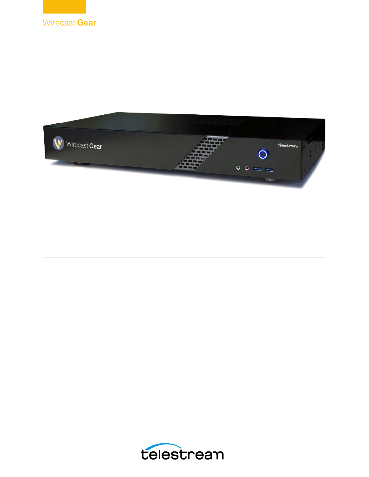
Wirecast Gear is an integrated solution for live production, streaming, video ingest and
more. It is designed to provide an easy to operate experience and is based on a
standard Windows 10 personal computer.
Note: Consult the Wirecast User Guide included with Wirecast Gear. You can download
this user guide from the Telestream web site at:
http://www.telestream.net/telestream-support/wire-cast/help.htm
Wirecast Gear Models
Wirecast Gear is available in these models:
•Wirecast Gear 110 - 4 Channel HDMI 250GB SSD Video Storage
•Wirecast Gear 210 - 4 Channel SDI 500GB SSD Video Storage
•Wirecast Gear 220 - 4 Channel SDI 2TB SSD Video Storage
•Wirecast Gear 230 - 4 Channel SDI 2TB SSD Video Storage
(with input and output capability)

Introduction to WC Gear
Unpacking Wirecast Gear
10
Features
•Windows 10 Pro 64-bit OS
•4 Port (SDI or HDMI) high quality video ingest
•Wirecast Pro
•Convertible mini case with rubber feet for table-top use and included rackmount
brackets for installing in approved flight/transport cases or in-place rack configura-
tions. Unit has no platter-based hard drives, making it ideal for transport
•Extensive source inputs including professional video connectors
•Multiple LAN/Wifi ports, USB 3.0 (including Type C) and more
•USB 3.0 (including Type C) and more
•Up to 4 channel ISO recording with full Instant Replay capability
•Three digital video output ports for multiple display configuration and on-site large
format display outputs (IMAG) with lowest latency including support for up to
UHD/4K resolutions
•Live source processing including scaling, rotation, color correction and keying.
•Compatible with industry standard applications such as Adobe CC, Microsoft Office
and most standard Windows 10 compatible applications/utilities
•System Refresh allows quick recovery to factory settings in case of system corrup-
tion or failure. All Telestream loaded applications will be recovered (user applica-
tions must be reinstalled)
Unpacking Wirecast Gear
Unpack the contents of the shipping container; identify each component and
determine that it has arrived in satisfactory condition.
If there is shipping damage to the box, note it on your shipping documents and contact
the carrier immediately. If the computer or box contents are damaged in any way, you
should file a claim with the carrier and notify Telestream immediately.
Note: Save the shipping container and packaging materials and store them in a safe
place. If you require service—or move your Wirecast Gear — the packaging materials
should be used for safe shipment.
Shipping Container Contents
Each Wirecast Gear box contains the following:
•Wirecast Gear computer
•Logitech Wireless Keyboard/Mouse combo
•Power cord

Introduction to WC Gear
Registering Wirecast Gear
11
•Accessory box - feet, screws, rack ears, rack ears, WiFi antenna
•Plastic bag
Registering Wirecast Gear
Registering your Wirecast Gear system is a requirement to gain access to your licensed
copies of Telestream-bundled software. It also ensures the following:
Safety—so you'll be kept informed of product feature updates and improvements
Service—to receive the excellent Telestream warranty service and technical support
Security—in the event of loss, theft or catastrophic events, your registration may serve
as proof of purchase for your insurance carrier
Registration is quick, easy, and important—follow these steps:
1. Go to the Wirecast Gear registration web page: http://www.telestream.net/
telestream-support/Wirecast-Gear/register.htm
2. Complete the Wirecast Gear registration.
3. Click Submit to complete registration.
Specifications
The following topics summarize Wirecast Gear specifications.
CAUTION: Wirecast Gear is a sealed device, with no user-serviceable parts or user-
accessible expansion slots. You should never open or attempt to upgrade or alter the
computer. Doing so exposes you to electrical hazard, may damage the unit, and may
invalidate your warranty. If you have hardware or software problems with your
Wirecast Gear, follow the steps in the Return Merchandise Authorization (RMA)
Procedure later in this guide to obtain service.
Operating System Specifications
Wirecast Gear is pre-installed with Windows 10 OS. Please see the Microsoft web site for
specifications.
Software Specifications
•Telestream Wirecast Pro application software
•Telestream Switch application software

Introduction to WC Gear
Specifications
12
•NewBlueFX Titler Live Standard, Advance NDI, or Ultimate
–Model 110 uses NewBlueFX Titler Present
–Model 210 uses NewBlueFX Titler Sport
–Model 220 & 230 uses NewBlueFX Titler Complete
Hardware Specifications
•Intel Core i7-6700 8M Skylake Quad-Core 3.4 GHz
•Intel HD Graphics 530
•Memory - DDR4 Dual Channel Memory
•System Drive - M.2 SATA System Drive
•Storage Drive(s) - High speed SATA 6Gb/s SSD (single or dual, depending on model)
•Video Ingest - 4-channel professional camera inputs with HDMI or SDI models available
•Motherboard features
–Intel® USB 3.0 with USB Type-C™
–802.11ac 867 Mbps dual band wireless (including antenna) + Bluetooth®
–115dB SNR HD Audio with Built-in Rear Audio Amplifier
–Dual Intel® GbE LAN RJ45
–PS/2 Keyboard/Mouse Port
–USB 3.0 Ports - 4 rear/2 front
–Display outputs - DVI-D, dual HDMI
•Wireless Keyboard and Mouse combo
•Power Supply: AC input, auto-sensing, suitable for most countries worldwide
–Input Range: 90 ~ 264Vac (RMS), Full Range Input
–Frequency: 47 ~ 63Hz
–Input Current: Max 6A (RMS) @ 115Vac, 3A (RMS) @ 230Va
•Dimensions: 16.55 x 9.85 x 2.25 inches, 1.3U rackmount height (rear brackets avail-
able for transport cases).
Note: Wirecast Gear has no user-serviceable parts. Any repair or additional PCI card
installation must be performed by Telestream or an authorized Telestream service
technician.

13
WC Gear
Panels
Introduction
The following topics describe the Wirecast Gear front and rear panels.
Note: Please do not make any connections just yet. First, read the panel and connector
descriptions and then proceed to the Installation of WC Gear topic for steps to install
and connect to the unit.
Wirecast Gear is available in HDMI and SDI configurations. Both configurations share
the same front panel features, but each configuration has a unique rear panel. Wirecast
Gear 100 series models include 4-channel HDMI professional inputs, while Wirecast
Gear 200 series models are SDI-based and use BNC connectors.
Topics
Front Panel
Rear Panel
Rear Panel Differences
WC Gear Panels
Front Panel
14
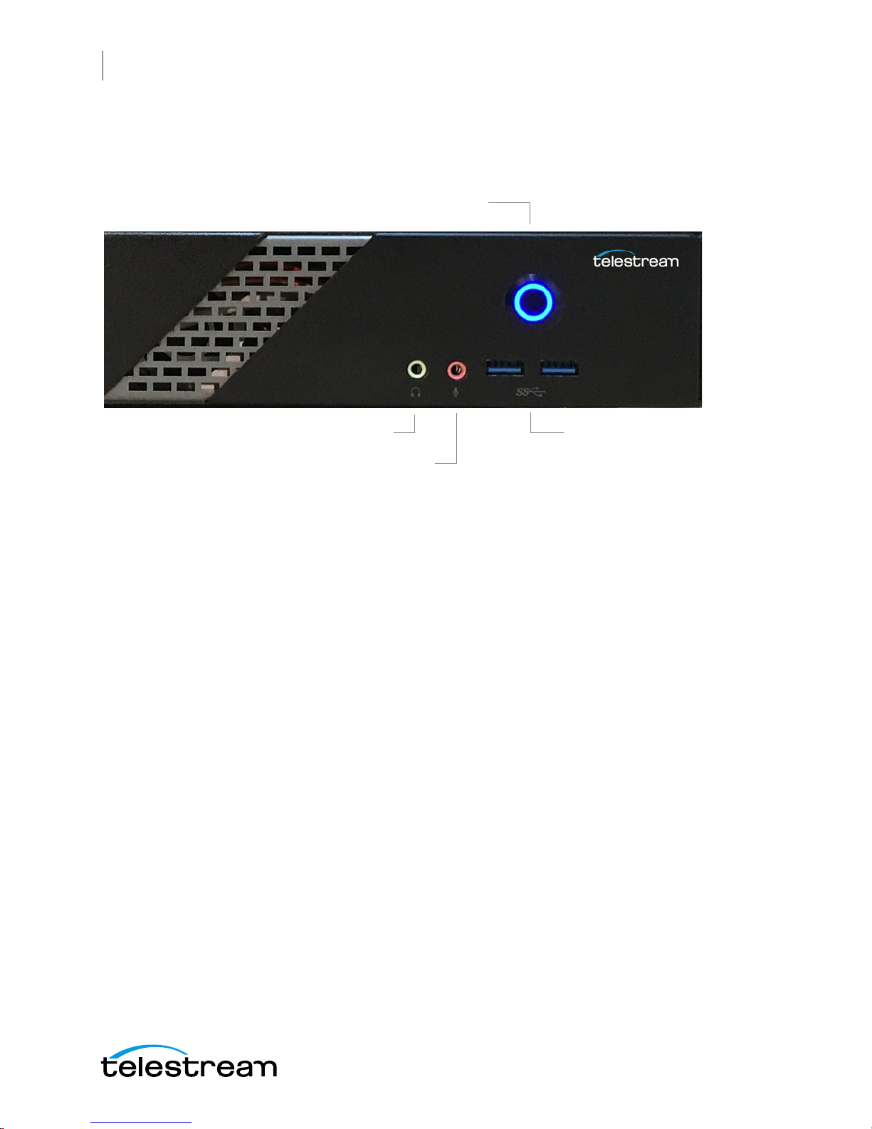
Front Panel
Wirecast Gear has the following connectors on the front panel.
1. Power Button This button turns the power on and off. When on, a blue light is
displayed.
2. Line Out (Green) Use this output for headphones or a speaker system. You can also
connect front speakers in a 4/5.1/7.1-channel audio configuration.
3. Mic In (Pink) Use this input for Microphones. Many live producers choose to use a
USB-based external audio configuration with either a simple A/D device with
professional connectors or a full audio mixer panel for tactile control of audio
levels. External devices must be USB 2.1 compatible. Contact the reseller who sold
you your Wirecast Gear unit for specific brand and model information.
4. USB 3.0 Port The USB 3.0 port supports the USB 3.0 specification and is compatible
to the USB 2.0/1.1 specification. Use this port for USB devices.
4. USB 3.0
2. Line Out (green)
3. Mic In (Pink)
1. Power Button

WC Gear Panels
Rear Panel
15
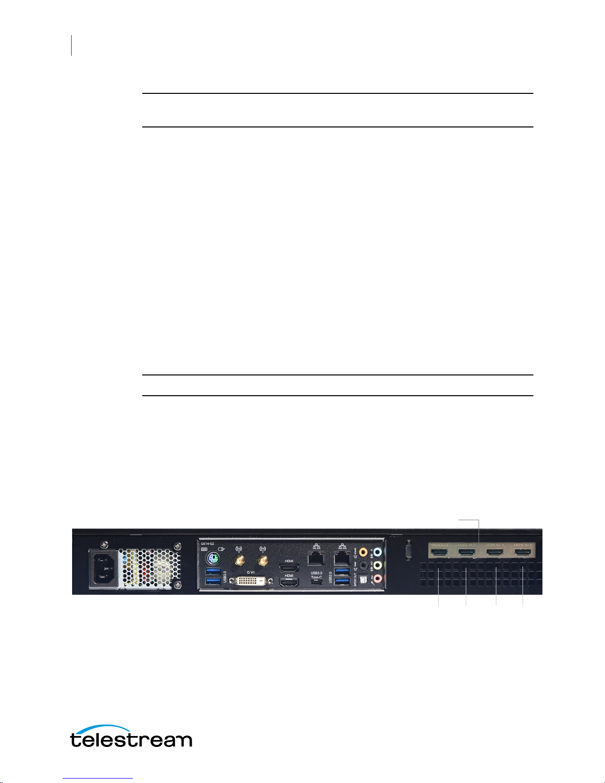
Rear Panel
The Rear Panel connectors have the following functionality.
1. PS/2 Keyboard/Mouse Port Use this port to connect a PS/2 mouse or keyboard.
2. SMA Antenna Connectors (2T2R) Use this connector to connect an antenna.
Tighten the antenna cables to the antenna connectors and then move the antenna
to a place where the signal is good.
3. RJ-45 LAN Port The Gigabit Ethernet LAN port provides Internet connection at up
to 1 Gbps data rate. The following describes the states of the LAN port LEDs.
4. Center/Subwoofer Speaker Out (Orange) Use this audio jack to connect center/
subwoofer speakers in a 5.1/7.1-channel audio configuration.
5. Rear Speaker Out (Black) This jack can be used to connect speakers in a 4/5.1/7.1-
channel audio configuration.
6. Line In (Blue) Line in jack. Use this for external audio devices other than
microphones.
7. Line Out (Green) Line out jack. This jack supports audio amplifying function. For
better sound quality, it is recommended that you connect your headphone/
speaker to this jack (actual effects may vary by the device being used). Use this
audio jack for a headphone or 2-channel speaker. This jack can be used to connect
front speakers in a 4/5.1/7.1-channel audio configuration.
8. Mic In (Pink) The Mic in jack. Microphones must be connected to this jack.
11. USB Type-C™
Port
12. HDMI
Output Ports
6. Line In
4. Center/Subwoofer
Speaker Out
1. PS/2 Keyboard/
Mouse Port
3. RJ-45
LAN Ports
9. Optical S/PDIF Out
5. Rear
Speaker Out
7. Line Out
8. Mic In
2. SMA Antenna
Connectors
10. USB 3.0/2.0 Ports
13. DVI-
D Port
WC Gear Panels
Rear Panel Differences
16
CAUTION: When removing any mic cable, pull it straight out from the connector to
prevent causing a short inside the cable connector.
9. Optical S/PDIF Out Connector This connector provides digital audio out to an
external audio system that supports digital optical audio. Before using this feature,
ensure that your audio system provides an optical digital audio in connector.
10. USB 3.0/2.0 Port The USB 3.0 port supports the USB 3.0 specification and is
compatible to the USB 2.0/1.1 specification. Use this port for USB devices.
11. USB Type-C™ Port The USB 3.0 port supports the USB 3.0 specification and is
compatible to the USB 2.0/1.1 specification. Use this port for USB devices.
12. HDMI Output Ports The HDMI port is HDCP compliant and supports Dolby® True
HD and dts® HD Master Audio formats. It also supports up to 192KHz/24bit 8-
channel LPCM audio output. You can use this port to connect your HDMI-
supported monitor. The maximum supported resolution is 4096x2160@24 Hz, but
the actual resolutions supported are dependent on the monitor being used.
13. DVI-D Port The DVI-D port conforms to the DVI-D specification and supports a
maximum resolution of 1920x1200@60 Hz (the actual resolutions supported
depend on the monitor being used). Connect a monitor that supports DVI-D
connection to this port.
Note: The DVI-D port does not support D-Sub connection by adapter.
Rear Panel Differences
Depending on the Wirecast Gear model, four HDMI (model 110) or SD/HD/3G-SDI
(models 210, 220, 230) video inputs are provided on the right side of the rear panel. The
location and numbering of inputs are shown below.
HDMI Input Connectors
Model 110 Rear Panel with HDMI
1 2 3 4

WC Gear Panels
Rear Panel Differences
17
Note: The default SDI number assignment on the model 230 are out of order and
differ from the numbering of the model 220.
Connect the inputs to your video sources, such as cameras, DVD players, computers,
editors, graphics cards, and other devices that produce a video output that you want to
use as an input for live production.
SD/HD/3G-SDI BNC Input Connectors
Model 210/220 Rear Panel with SDI BNC
SDI 4 SDI 2
SDI 3 SDI 1
SD/HD/3G-SDI BNC Input Connectors
Model 230 Rear Panel with SDI BNC and Ref Input
SDI 1 SDI 2
REF SDI 3 SDI 4

WC Gear Panels
Rear Panel Differences
18

19
Installation of
WC Gear
Introduction
This section shows you how to install WC Gear. This includes physical mounting and
wireless connections.
Note: Before installing WC Gear, read through the section on WC Gear Panels.
Topics
Physical Mounting
Wireless Connections
Physical Mounting
Wirecast Gear comes configured for table-top use with the included feet pre-attached.
The unique size and shape of Wirecast Gear is designed to occupy a minimum of space
while making connectors and cables easily accessible.
Also included with all Gear systems are two rack-mount "ears" and screws that allow the
system to fit into a standard 19-inch rack and take up 1.3 RU (Rack Units). This
configuration is useful for in-place racks and mobile flypacks where convenient and
safe transport of your live production system is required.
Note: The rack-mount configuration will require removal of rubber feet remove the
vent warning label on top of the unit, if desired. It is there to remind you to never block
the top of chassis air vents.
Wireless Connections
To make connections to your Wirecast Gear system, refer to WC Gear Panels for
connector functions and locations, and then follow these steps.
Installation of WC Gear
Wireless Connections
20
Note: The Wirecast Gear system is configured to work with up to three displays.
1. If you plan to use Wifi, connect the antenna to the two jacks and position the
antenna as desired.
2. If available, plug a network cable into one of the available RJ45 Ethernet jacks.
Note: After it is powered on, Wirecast Gear will attempt to automatically connect to
your installed network configuration (via LAN). If your network requires authentication
or specific configuration, please check with your network administrator to determine
computer and network setting requirements.
3. Plug HDMI or SDI cables into the 4 video input connectors on the right rear panel.
4. Plug a standard computer monitor into either the HDMI or DVI monitor output
ports on the back of the unit.
Note: Every Wirecast Gear unit has two HDMI outputs and one DVI-D output. These
are standard display outputs that are used for connecting computer monitors. If you
have more than one monitor installed, Wirecast will allow you to send a full screen
output of your program to the second display as a program monitor. These are also the
ports to be used for in-venue, presentation displays (also known as IMAG) as they
provide for the lowest latency output.
5. Make audio input and output connections to Line In, Mic In, Speaker Out, and
Optical S/PDIF Out.
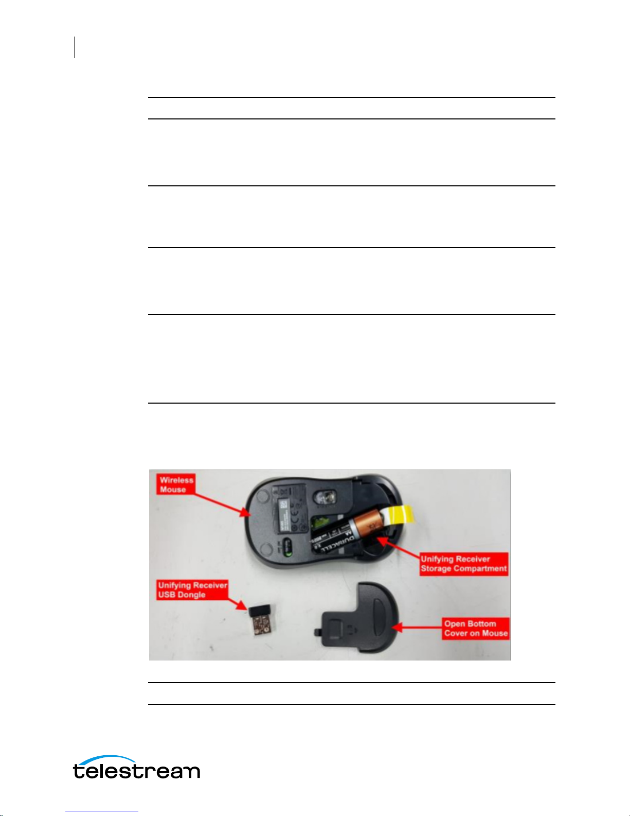
6. Remove the USB dongles from the bottom of the wireless mouse.
Note: The mouse dongle communicates to both the mouse and the keyboard.
This manual suits for next models
3
Table of contents
Other Telestream Media Player manuals


