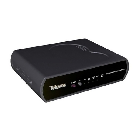
Televes 769301 User manual

Ref.769301
Data Over Coax Gateway

Content Index
Important safety information..................................................................................................................... 4
Main installation considerations...................................................................................................................4
Safe operation..............................................................................................................................................4
Electric security markings............................................................................................................................4
Introduction............................................................................................................................................... 5
Data Over Coax Gateway............................................................................................................................5
Main Specifications......................................................................................................................................5
System requierements ................................................................................................................................6
Package content ........................................................................................................................................ 7
CoaxData range of products........................................................................................................................8
Getting to know the Data Over Coax Gateway....................................................................................... 9
Device connections......................................................................................................................................9
Front & rear pannel LEDs ......................................................................................................................... 11
Data Over Coax Gateway Configuration................................................................................................ 12
Web Interface Access................................................................................................................................ 12
Device Status.............................................................................................................................................12
Setting up WAN mode............................................................................................................................ 17
AP Bridge Mode.........................................................................................................................................17
Router Mode.............................................................................................................................................. 17
Setting up LAN interface........................................................................................................................ 18
WiFi interface set up............................................................................................................................... 19
Configuration of the radio interface............................................................................................................20
WiFi Access Point Configuration................................................................................................................22
Multiple VAP Restrictions...........................................................................................................................23
Security configuration of WiFi network ..................................................................................................... 23
Setting WPS...............................................................................................................................................25
Create custom Bridges and Vlan interfaces........................................................................................... 26
System Interfaces description....................................................................................................................26
Operation Modes....................................................................................................................................... 26
Creating VLAN interfaces on the device....................................................................................................27
Creating VLANs on the device's Switch.................................................................................................... 27
Creating Bridge interfaces on the device...................................................................................................29
Advanced Device Configuration............................................................................................................. 32
Default Configuration Behavior .................................................................................................................32
Internet test ...............................................................................................................................................33
Routing tables............................................................................................................................................34

Setting up system time...............................................................................................................................34
Advanced NAT Configuration.....................................................................................................................35
Changing account password .................................................................................................................... 37
Device Management..................................................................................................................................38
Log Management.......................................................................................................................................39
User Web account..................................................................................................................................... 40
Installing Data Over Coax Gateway....................................................................................................... 41
Setting up Coaxdata Master...................................................................................................................... 42
Connecting CoaxData Master....................................................................................................................42
Install 769301 Slave on TV outlets. .......................................................................................................... 43
Specifications......................................................................................................................................... 45

Data Over Coax Gateway Ref.769301
4
Important safety information
Main installation considerations
Please read this manual carefully before installing the product.
To reduce risk of fire or electrical schock do not expose the equipment to rain or dampness.
Do not remove product cover while being connected to the mains.
Do not block ventilation holes on the product.
Please allow for some free space around the product to guarantee proper air circulation.
Product should not be exposed to watter splash. El aparato no debe ser expuesto a caídas o
salpicaduras de agua.
Do not place product near heat sources or high humidity enviroment.
Do not install the equipment in an unstable or vibrating surface where it could face a schock.
Safe operation
Mains power requirements for this product are: 108-254 V~ 50/60 Hz.
Should any liquid or object fall inside the product, please refer to technically qualified service.
To unplug the product from the mains please pull from the mains plug, never from the electrical
cable.
Do not connect the product to the mains untill all other connections have been made.
The power socket should be near the equipment and easily accessible.
Electric security markings
CE marking compliance.
Product for indoor use.
Safety requirements for class II electrical products.
Waste management of electric and electronic equipment at the end of their working live.
www.televes.es
ENGLISH

Televes
®
5
Introduction
Data Over Coax Gateway
The Data Over Coax Gateway allows the transmission of IP Data Over Coaxial cable and power
distribution neworks as well as broadcast TV and other services.It includes a WLAN interface 802.11bgn
for wireless devices.
The Ethernet-Coaxial-Wifi Router allows the connection of multiple devices through the coaxial and power
network without the need of running extra cables and installing Hub's or Ethernet switches.
Ref.769301 Data Over Coax Gateway includes power supply connector, two F connectors for TV and
DATA, three Ethernet RJ45 00Base-TX/ 0Base-T an USB connector and a WLAN 802. bgn interface.
Main Specifications
Possibility of connecting a device sharing internet access using the existing infrastructure taking
advantage of wireles technology.
Easy settting up procedure without the need of installing new hardware and/or software drivers.
3xEthernet (Ref.769301) 100 BASE-TX/10 BASE-T to allow the connection of multiple devices
such as PC's, Set to boxes, video game consoles, etc.
WiFi 802.11bgn interface with 2x2 MIMO in the 2.4GHz band supporting up to 144 Mbps for
20MHz channels and up to 300 Mbps for 40MHz channels.
Posibility of switching off WiFi or selecting a low power mode interface by means of front panel
switch.
WPS (Wireless protected setup button) feature avoiding the need of password setting.
Supporting all encryption and authentification WiFi protocols such as WEP, WPA/WPA2, 802.1x
guaranteeing a secure connection.
Complying with IEEE 1901 specifications and including HomePlug AV PHY supporting 2880 p
OFDM 4096/1024/256/64/16/8 QAM, QPSK, BPSK and ROBO mode carriers, capable of up to
700 Mbps physical throughput and up to 350Mbps UDP throughput over the coaxial network.
Working bandwidth on the coaxial network is 2-67,5 MHz supporting a maximum attenuation of 85
dB. There is no limit of minimum attenuation. It can support up to 1,2 Km of coaxial cable.
5 front LED’s show equipment status, Internet access, WiFi status, coaxial network status.
www.televes.es
ENGLISH

Data Over Coax Gateway Ref.769301
6
Dynamic signal adjustment based on channel conditions and powerful coding algorythm based on
FEC & TCC (turbo convolutional codes) technique allowing communication with just 3dB of SNR.
Advanced Encryption algorithm (AES-128) guaranteeing secure communications.
Sharing high speed internet access. Supporting up to 243 slaves in the same distribution network.
No need of Ethernet Hubs or switches.
Supporting Quality of Service (QoS) and including packet classification rules and multiple
transmission ques.
Supporting IGMPv3 based multicast streams to implement efficient IPTV solutions. It can handle
up to 32 different channels.
Wide range power supply unit ~108-254Vac 50/60Hz
Robust and compact design in compliance with electrical safety legal requirements (EN 60950-
1:2007/AC:2012), electromagnetic compatibility (EN 55022:2008) , inmunity(EN 55024:2011 ) and
radiation over electric power wiring (EN 50412-2-1:2006 ) and electromagnetic spectrum (EN 300
328 V1.7.1, EN 62311:2008).
Web interface to configure working parameters and network options.
System requierements
Plug and Play system avoiding the need of any additional software or driver.
To configure the device it is needed a computer with an Ethernet 00BASE-TX or IEEE 802. bgn
WiFI port.
Complete web based software tool and advanced configuration application CoaxManager™
(basic configuration)/ CoaxManagerPro™ (advanced configuration). Software is avaliable on
www.televes.com.
www.televes.es
ENGLISH

Data Over Coax Gateway Ref.769301
8
CoaxData range of products
Ref.769301 is a part of a comprehensive range of products:
•Ref.769201 CoaxData™ 1Gbps-HDTV
•Ref.769202 CoaxData™ 1Gbps-HDTV with SFP
•Ref.769203 CoaxData™ 1Gbps-HDTV 1XEth
•Ref.769220 CoaxData™ Diplex filter TV-Data 2-68 Mhz / 87-2150 MHz
•Ref.769210 CoaxData™ SFP 1000 Base-X 2 F.O ethernet adapter.
Ref.769201 CoaxData™
1Gbps HDTV Ref.769202 CoaxData™
1Gbps HDTV with SFP
Ref.769203 CoaxData™
1Gbps HDTV 1x Eth
Ref.769210 CoaxData™
SFP Mod le 1000 Base-X
Ref.769220 CoaxData™ 1Gbps
diplex filter TV-Data 2-68 Mhz /
87-2150 MHz
www.televes.es
ENGLISH

Televes
®
9
Getting to know the Data Over Coax Gateway
Device connections
Ethernet ports
3 x RJ-45 ports IEEE 802.3 00 BASE-TX/ 0 BASE-T compliant. These ports allow the connection of the
CoaxData Gbps-HDTV to computers, VOIP telephones, Set Top Boxes, connected TV’s,etc. Each RJ45
support speed autonegotation and Auto-MDIX for ease and optimal working conditions.
Data input. TV + Data
Female F connector for data and TV input direct from the compatible TV socket.
TV output. TV
Female F connector to access TV channels.
Reset button / factory default configuration
Keeping the button pressed for a period under 5 seconds the device will reboot if the button is pressed for
more than 5 seconds it will reload factory configuration.
Please take into consideration that factory default will delete all configuration done on the
equipment.
Configuration of coaxial interface of the product will be affected by this button and reset to factory.
Please note this as this is managed by using the CoaxManager application.
IP default address is : 172.16.0.1/Mask: 255.255.255.0
Default user: Admin password: Televes1
Medium switch
At the back of the device this selects the transmission medium. Coaxial only (right), hybrid (coaxial & PLC)
(left).
Signal will always be present on the coaxial network.
The Medium LED on the front panel will bright green (Coaxial mode) or orange (Hybrid mode).
www.televes.es
ENGLISH

Data Over Coax Gateway Ref.769301
10
WPS Button
WPS (Wireless protected setup) allows the easy configuration of a wireless secure connection with other
devices supporting the WPS protocol. Siply push the button and activate the WPS function on the wireless
device.
The WPS function will be active for 2 minutes, during this period of time the client should stablish a secure
connection.
While the WPS mode is active the power LED will blink orange, once the connection has been finalised the
WPS mode will stop and should a connection to a different device be needed the WPS button should be
pressed again.
WiFi switch
WiFi Switch allows three positions and hence WiFi status:
OFF (left ): radio is off, LED will bright red indicating that device has been turned off WiFi.
Low Power (Center): WiFi radio will be on in low power mode. This mode will reduce exposure to
radiation and interference in nearby networks. The maximum radiated power will not exceed
3dBm. In this mode the WiFi LED will bright orange.
Normal (Right): WiFi radio will be on in normal mode. The maximum radiated power will be of 17
dBm In this mode the WiFi LED will bright green.
www.televes.es
ENGLISH

Televes
®
11
Front & rear pannel LEDs
The product has 5 LED’s on its front pannel show different working conditions of the device. Furthermore 3
LED’s on the rear pannel show status and activity of the ethernet ports.
Power LED
This LED shows the status of the device.
Green: Normal working conditions.
Orange: Device is booting and loading configuration. The product will use this colour to indicate
configuration events such as the activation of the WPS mode.
Red: Indicates that the device has detected an error while booting.
Internet LED
This LED indicates the status of the connection to the internet.
Green: The device is connected to the internet.
Red: The device is not connected to the internet. Verify all connections of the equipment and the
correct configuration of the gateway supplied by the ISP.
Orange: The device has been configured to AP Bridge. In this working mode there is a bridge
between the three interfaces Ethernet-Coaxial/PLC-WiFi.
WLAN LED
This LED shows the status of the WiFi network.
Green: WiFi is On. Maximum output power +17 dB.
Orange: WiFi is ON in low power mode. Maximum output power is +3 dBm.
Red : WiFi en OFF.
Medium Coaxial / Hybrid LED
Shows the selected transmission medium on the front pannel switch.
Green. Coaxial only.
Orange. Hybrid, Coaxial + PLC. Connection stablished through both coaxial & power line network.
Link status LED
This LED indicates both the quality of the connection and the activity on the coaxial/power line interface.
•Green: Higher quality connection.Optimal performance.
•Orange: Good quality connection.
•Red: Poor quality connection.
Ethernet LED’s
Each back pannel ethernet port has an LED indicating link up as well as activity on the port. Each RJ45
port supports speed autonegotiation.
www.televes.es
ENGLISH

Data Over Coax Gateway Ref.769301
12
Data Over Coax Gateway Configuration
Web Interface Access
The configuration of the device has to be carried out by means of a web browser.
Connect a device with a web browser to the Data Over Coax Gateway and access the IP address:
http://172.16.0.1 Default user is. Admin and default password is : Televes1.
To increase security, change account password through configuration options on the Device
Management section.
If you forgot Username and/or Password please reset equipment to factory configuration with
factory button. Press button for at least 5 seconds.
Device Status
Device Information: Information about firmware and hardware version on the product.
www.televes.es
ENGLISH

Televes
®
13
Network Information: Shows network information of the device. This information is related to the selected
working mode of the product.
•AP Bridge mode: The device will work as an ethernet bridge on the three interfaces Coaxial/PLC-
Ethernet-WiFi.
Service Mode: Internet
Connection Name: 1_INTERNET_B_VID_0
Protocol: PPPoE_Bridged
•Router mode : In this mode the option shows information related to the conection stablished by the
ISP’s router. In this mode there is a WAN interface (Coaxial/PLC) and interfaces for the LAN
network Ethernet & WiFi.
Service Mode: Internet
Connection Name: 1_INTERNET_R_VID
Default Gateway/Subnet Mask: IP address being giben by the ISP’s gateway.
DNS Server: DNS server being being determined by the Gateway.
www.televes.es
ENGLISH

Data Over Coax Gateway Ref.769301
14
Packets counters for the WAN Interface supply information about the activity on this interface.
•User Information: Information is supplied on the LAN interfaces and status of the WiFi interface,
working mode and packets counters.
•Scan for Wireless Networks: Provides information of current wireless channels that are active and
the method of authentication to connect to them
www.televes.es
ENGLISH

Televes
®
17
Setting up WAN mode
The working mode hast to be set through the Web interface on the Network Settings. Device has two
operating modes depending on the type of network deployed.
AP Bridge Mode
AP Bridge: This mode brings up a local
network where communication between all
interfaces is allowed. This type of network
is mostly indicated for home use.
NOTE: When AP Bridge Mode is set
CoaxManager(Pro)™ application can be
used to configure the coaxial/plc interface.
Router Mode
Router: This is the factory default working
mode. Under this mode the device will
route between the coaxial/plc (WAN)
interface and the Ethernet / WiFi (LAN)
interfaces.
In this mode the CoaxManager(Pro)™
can only be used to connect remotely to
the modem via Coaxdata master of
coaxial installation.
www.televes.es
ENGLISH

Data Over Coax Gateway Ref.769301
18
Router mode supports three protocols depending on the type of access to the internet: DHCP (Automatic),
Static Configuration and PPPoE.
DHCP: This mode sets the configuration of
the WAN interface (coaxial/PLC) through a
DHCP server connected to the Master of the
network.
Static Configuration: Allows the manual
configuration of the IP parameters of the
WAN interface.
IP Address/Subnet Mask:
Gateway: IP address of the router
connected to the Master device.
DNS: IP address of the Domain Names
Server
PPPoE(Point-to-point protocol over Ethernet):
connection on the WAN interface is
established through a PPPoE connection.
This configuration needs a PPPoE server on
the WAN side.
User: PPPoE user name
Password: service password
Connection Trigger: Indicates wether the
connection is stablished On demand or
always On.
Setting up LAN interface
The product includes a LAN interface to stablish connection between the local devices and internet and to
build a bridge between the ethernet ports and the WiFi network.
LAN Settings: This options configures IP address and network mask of the LAN inferface.
DHCP Server: Allows activation of DHCP server which will assign addresses dynamically to each
device. The range of IP’s and lease time can be also defined.
Restricted IP Address List: Device connected on the LAN needs a static IP address. This can be
set by matching desired IP address with MAC Host address in the DHCP server. A typical
application for this would be servers, STB’s, etc.
www.televes.es
ENGLISH

Televes
®
19
WiFi interface set up
Wifi settings have the following options
•Save/Delete/Cancel: Save: Saves configuration changes; Delete: Deletes currently selected VAP;
Cancel: Deletes all changes made on wlan settings web page and restore to original values.
•Wireless Info: Provides information about the state of Wi, current channel, and the number of
stations currently connected to AP
•Scan for wireless network: Provides channel information of wireless AP that are active, the
channels occupied and methods of authentication. This option allows you to to select the most
appropriate AP channel depending on the already occupied channels.
www.televes.es
ENGLISH

Data Over Coax Gateway Ref.769301
20
The configuration of this interface hast two different elements:
•Radio configuration: RF network parameters can be configured; Operation Mode, frequency, and
bandwidth use.
•Access point configuration: VAP (virtual access points) can be configured. For each network the
SSID name and the security should be set.
Configuration of the radio interface
The WiFI interface supports the IEEE 802.11bgn standard.
Enable Radio: Activate WiFi network. This option is controlled by the switch located on the front
pannel of the product and is not available on web. In case you want to use this option, you need to
disable wifi switch on web page in Device Management> Advanced Management.
WiFi Mode: Selects the WiFi mode
Standard Description
802.11b 802.11 supporting 11Mbps througput
802.11g 802.11 supporting 54Mbps througput
802.11ng20 802.11n supporting 144Mbps, througput with
20Mhz bandwidth channels.
802.11ng40plus
802.11ng40minus 802.11n supporting 300Mbps througput with
40Mhz bandwidth channels.
Channel: Indicated the channel being used by the WiFi network.Occupied bandwidth depends on
WiFi mode. There are 13 possible channels.
www.televes.es
ENGLISH
Other manuals for 769301
2
Table of contents
Other Televes Gateway manuals
Popular Gateway manuals by other brands

HMS Networks
HMS Networks Ewon Netbiter EC300 Series Startup guide

ZyXEL Communications
ZyXEL Communications ZyWALL USG 100 Series quick start guide

3Com
3Com PathBuilder S200 Series manual

Innov
Innov rm pro user guide

Philips
Philips Dynalite DDNI-LON installation instructions

Vertical
Vertical Xcelerator IP quick start guide