Televes DVB-S2 COFDM User manual

Ref. 563101
www.televes.com
DVBS2 - COFDM
EN User manual


Index
EN
ENGLISH
1. Technical specifications ...................................................................................................................... 5
2. Reference description ......................................................................................................................... 7
3. Mounting ............................................................................................................................................. 8
3.1. Wall mounting .............................................................................................................................. 8
3.2. 19” rack mounting ...................................................................................................................... 9
4. Element description ............................................................................................................................ 10
4.1. Introduction .............................................................................................................................. 10
4.2. Power supply unit ..................................................................................................................... 11
4.3. Amplifier .................................................................................................................................. 12
4.4. Universal programmer ............................................................................................................. 13
5. How to use the product ...................................................................................................................... 14
5.1. Main menu ............................................................................................................................... 14
5.2. Extended menu ......................................................................................................................... 16
5.3. Parameters saving .................................................................................................................... 18
6. Selecting the DVB-T output mode in DVBS2-COFDM transmodulators ........................................... 19
7. Controlling the device ........................................................................................................................ 21
8. Distribution of 7 channels of DVBS2-COFDM T0X ............................................................................. 22
9. Norms for rack mounting .................................................................................................................... 23
10. Norms for cabinet mounting ............................................................................................................... 25
A. Channels table .................................................................................................................................... 27
DVBS2 - COFDM


EN
5
Satellite
Demodulator
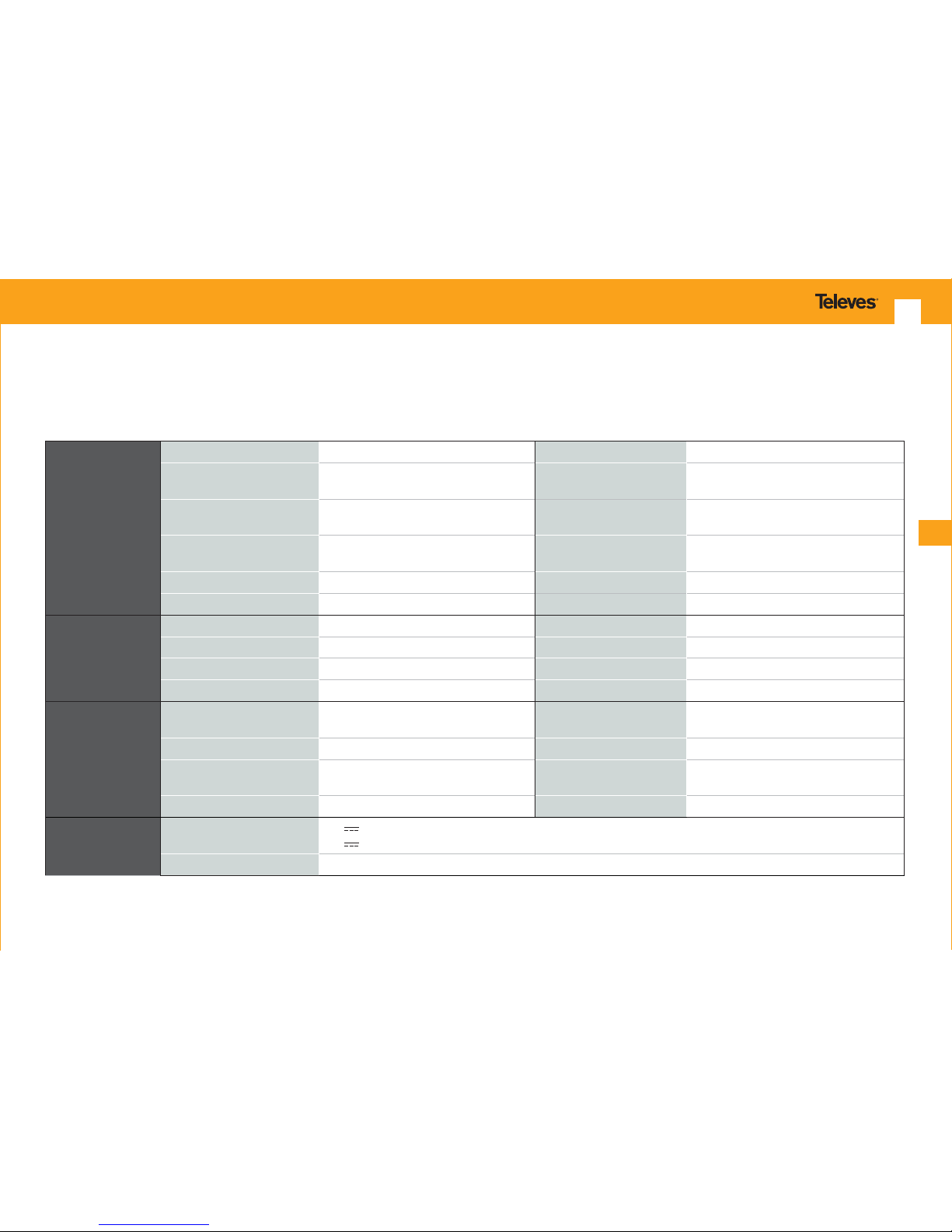
Input frequency 950 - 2150 MHz Through loss < 1,5 dB typ.
Symbol rate 10-30 Mbaud (QPSK- 8PSK) Modulation DVB-S2 (QPSK, 8PSK)
DVB-S (QPSK)
Frequency steps 1 MHz Internal FEC LDPC (9/10, 8/9, 5/6, 4/5, 3/4, 2/3, 3/5,
1/2, 1/4, 1/3, 2/5)
Input connectors
and output “F” female External FEC BCH (Bose-Chaudhuri-Hocquenghem)
Input impedance 75 ohm. Roll-o factor 20%, 25%, 35%
LNB power supply 13/17V/ OFF 22KHz (ON/OFF) Input VSWR 10 dB min.
COFDM
Modulator
Modulation format QPSK, 16QAM, 64QAM Scrambling DVB ET300744
Guard interval 1/4, 1/8, 1/16, 1/32 Interleaving DVB ET300744
FEC 1/2, 2/3, 3/4, 5/6, 7/8 Cell_id Selectable
Bandwidth 7 MHz, 8 MHz Output spectrum Normal / Inverted (Selec.)
RF output
Output frequency 177 - 266 / 474 - 858 MHz (CH mode)
45 - 862 MHz (Frequency mode) Through loss < 1,5 dB typ.
Frequency steps 166 KHz Return loss > 12 dB typ.
Maximum output level 80±5 dBV (progr.) Input and output
connectors “F” female.
Attenuation >15 dB (prog) Output impedance 75 ohm.
General Consumption* 24V : 270 mA (LNB power OFF)
24V : 480 mA (LNB power ON)
Index of protection IP20
1. Technical characteristics
1.1. DVBS2-COFDM ref. 563101
* For the LNB it is considered a standard consumption of 300 mA.
The technical characteristics described are dened for a maximum ambient temperature of 45°C (113ºF). Forced ventilation is used for higher temperatures.

DVBS2 - COFDM 6
Amplier
5575
Frequency range 46 ... 862 MHz Connector “F”
Gain 44 ± 2,5 dB Power supply 24 V
Regulation margin 20 dB Consumption at 24 V 450 mA
Output level (60 dB) 105 dBµV (42 CH CENELEC) Test socket -30 dB
Amplier
451202
Frequency range (1) 47 ... 862 MHz Connector “F”
Gain (1) 40 - 53 dB (selec.) Power supply 196 - 264 V~ 50/60 Hz
Maximum output level (1) 129 dBµV (typ.) (DIN 45004B) Max. Power 16 W
Frequency range (2) 5 ... 30 MHz Test socket -20 dB
Gain (2) 20/ -3 dB (typ.)
Maximum output level (2) 129/ --- dBµV (typ.) (DIN 45004B)
Power supply unit
5629
Mains voltage 196 - 264 V~ 50/60 Hz Total max. current
(outpur 1 + output 2)
5A (24V )
Output voltage 24V Max. current per output
4A (24V )
1.2. Technical specs. Broaband Ampliers
1.3. Technical specs. Power Supply Unit
(1) Main channel (2) Return channel (active/passive)
1.4. Blocks Diagram
Demodulator
DVB-S
DVB-S2
TS Processing
Modulator
COFDM
INPUT
SAT
Up
Converter OUTPUT
TDT

EN
7
2. Description of references
Range
563101 DVBS2-COFDM T-0X
5575 Broadband Amplier 44dB 120dBµV T-0X
451202 Amplier DTKom (47 - 862 MHz)
5559 Headend Manager CDC-IP T-0X
555901 Headend Manager CDC-IP GSM T-0X
5629 Power supply unit 24VDC/5A T-0X
Accessories
7234 Universal Programmer
5071 T03-T05-T-0X Mounting rail (50 cm)
5239 T03-T05-T-0X Mounting rail.12 Modules+PSU (56 cm)
5301 19” Subrack frame
507202 T-0X Lockable cabinet with Ventilation Unit (7 Modules + PSU)
4061 75 Ohm DC-Block load
4058 75 Ohm Load
422601 T05 to T-0X Power connection lead (40 cm)
422602 T05 to T-0X Management connection lead (40 cm)
422603 T-0X Management connection lead (1m)
5673 Blank plate 50 mm

DVBS2 - COFDM 8
ABC
PRGM
DVBS 2-COFDM
DVBS 2-COFDM
DVBS 2-COFDM
DVBS 2-COFDM
PRGM
DVBS 2-COFDM
PRGM
DVBS 2-COFDM
BROADBAND AMPLIFIER
TEST
(-30dB)
1
2
CLAC!
3. Mounting
3.1. Wall mounting
7234
NOTE: The use of both source outputs is recommended, balancing the consumption. For example, 4+3 or 3+4 modules
5575
4061
5071
5239
563101
5629 IF satellite
input
Output
COFDM

EN
9
3.2. 19” rack mounting
02340039001 003
02340043001 003
CTRL
PRGM
DVBS2-COFDM
PWR
02340043001 003
CTRL
PRGM
DVBS2-COFDM
PWR
02340043001 003
CTRL
PRGM
DVBS2-COFDM
PWR
02340043001 003
CTRL
PRGM
DVBS2-COFDM
PWR
02340043001 003
CTRL
PRGM
DVBS2-COFDM
PWR
02340043001 003
CTRL
PRGM
DVBS2-COFDM
PWR
02340038001 002
02340038001 002
BROADBAND AMPLIFIER
PWR
TEST
(-30dB)
5301

DVBS2 - COFDM 10
The MPEG2 transport package is then modulated
in COFDM format and converted to the output
channel (UHF or VHF and with a maximum
bandwidth of 8 MHz) using an agile up-converter.
The DVBS2 transmodulator with COFDM receives
a satellite transponder in some DVBS (QPSK) or
DVBS2 (QPSK or 8PSK) modulation formats and
demodulates it by obtaining an MPEG-2 transport
package.
The programming of the transmodulator operating
parameters (input frequency, output channel,
modulation format and adaptation of services
mainly) is performed through the universal
programmer (ref. 7234).
4. Identification of the system elements
4.1. Introduction
02340043001 003
CTRL
PRGM
DVBS2-COFDM
PWR
6
7
8
5
1
3
2
4
1. IF satellite input
2. IF satellite output
3. RF input
4. RF output
5. Module power supply input
6. Status LED
7. Control BUS connector
8. Programmer / PC connector

EN
11
4.2. Power supply unit
Connectors
to power the
modules (1)
On LED
(1)
Mains input
230V~
02340039001 003
CTRL
DVBS2-COFDM
PWR
NOTES: - The power source can supply a maximum of seven DVBS2-COFDM T0X modules.
- Whenever the demand of power exceeds 4A (max. current for each output), it is necessary to distribute it between the two powering outputs
of the PSU.
24V: OK
0V: Overload or short circuit
24V
24V
24V
0V
0V
24V
GND

DVBS2 - COFDM 12
4.3. Broadband amplier
OPTION “A” - 5575 OPTION “B” - 451202
1
3
2
4
5
6
7
02340038001 002
BROADBAND AMPLIFIER
PWR
TEST
(-30dB)
I. m x 150mA
196-264V~ 50/60Hz
Fuse: T1A L 250V
USO EXCLUSIVO EN INTERIOR
FOR INDOOR USE ONLY
¡¡¡ATENCIÓN!!!
NO ABRIR. TENSIONES ELEVADAS DENTRO
¡¡¡WARNING!!!
DO NOT OPEN. LIVE PARTS INSIDE
Test IN
-20 dB
MATV
10 dB 10 dB
C. Ret
OK - Return
OK - MATV
20 dB20 dB
Test OUT
-20 dB MATV
+10 dB
C. Ret
On
Ret.
IN
Ret.
OUT
MATV 20 dB
02340019002
1 2 3 4 5 6 7
It features two input connectors, to allow mixing of channels coming
out from two different systems. If only one of the inputs is used, it is
recommended to load the unused input with a 75 ohm terminator, ref 4061.
As the rest of T-0X units, this amplier is powered via the 24 Vdc power BUS.
Input signals through connectros 3 & 4 are combined and amplied in the frequency band 47-862 MHz
1. RF output
2. Test socket (-30 dB)
3. RF input
4. RF input
1. Mains power supply input (196-264 V~ 50/60 Hz)
2. Ground connection
3. Power LED
4. MATV input
Return channel output
5. MATV input test
6. MATV output test
7. MATV output
Return channel input
5. Powering BUS connectors
6. Status LED
7. Gain attenuator

EN
13
4.4. Universal Programmer PCT 5.0
ABC
PCT 4.0 UNIVERSAL
The programmer consists of 4 buttons:
(short press) - Selection of parameter
(positioning of the cursor).
-Modication of the parameter chosen by
the cursor (ashing)
(short press) - Change menu
(long press) - Change between Principal
and Extended menus
(long press) - Save changes to memory
+ Cloning menu.
+ + Increases the contrast of the screen.
+ + Decreases the contrast of the screen.

DVBS2 - COFDM 14
5.1. Normal menu
a. Input menu
The rst main menu lets you select the input
frequency, the symbol rate of the input signal
and the power supply of the LNB converter
(0, 13v22KHz, 13v, 17v22KHz or 17v).
INPUT
Freq.: 1234MHz
27.500 Kbaud
LNB:13 22KHz
To make a change press the key until the desired
parameter ashes. This eld can be then be
changed by means of the keys and .
The range of values allowed for the input frequency
is 950-2150 MHz, whereas for the symbol rate the
range is 10 to 30 Mbaud.
In case of a ‘short-circuit’ in the input connector
(power supply enabled for the LNB) the LED on
the front of the module ashes until this condition
disappears.
5. - Instructions for use
Insert the programmer in the front connector of
the module programming (“PRGM”). First, the
programmer’s rmware version will appear:
PCT firmware
version
------------
:5.3
The rmware version of the DVBS2 – COFDM
module is shown below:
Unit
Firmware
version:
1.05
b. COFDM1 modulation menu
The next main menu allows various COFDM output
modulation parameters to be selected:
COFDM >>
8MHz 64QAM
GI:1/8
FEC:3/4
The parameters that can be selected in this menu
and their possible values are as follows:
• Bandwidth of the COFDM signal: 7MHz or
8MHz.
• Modulation: QPSK, 16QAM or 64QAM.
• Guard interval: 1/4, 1/8, 1/16 or 1/32.
• FEC: 1/2, 2/3, 3/4, 5/6 or 7/8.

EN
15
c. COFDM2 modulation menu
In the next main menu you can select the
parameter cell_id (cell identier) of the COFDM
modulation:
COFDM
Cell_id:
0x0000
d. Output menu
The next main menu shows the frequency or
output channel, the output oset (only in channel
mode), the level control and the selection of
output spectrum inversion.
OUTPUT
Ch:C21 Of:0
(474.000 MHz)
Lev:99 Norm.
OUTPUT
Freq: 474.000
Level: 99
IQ: Norm.
To change the frequency press the key until the
desired parameter ashes. This eld can be then be
changed by means of the keys and .
In frequency mode you can select any output
frequency value between 45 - 862 MHz. The
decimal part depends on the dierence of
frequency chosen (see extended menu b). If you
select a dierence of 125 KHz the permitted values
for the decimal part are 0, 125, 250, 375, 500, 625,
750 and 875 KHz. With a dierence of 166 KHz the
possible values are 0, 166, 333, 500, 666 and 833
KHz.
The output level control permits values between
00 and 99.
The possible values for the output spectrum
inversion are “Norm.” (not inverted) and ‘Inv.’
(spectrum inversion).
In channel mode it lets you select an output
channel from the table selected as well as the oset
regarding the channel’s receiving point frequency.
The permitted oset values depend on the
frequency dierence selected (see conguration
menu):
• Steps of 125KHz: ±4 (-500, -375, -250, -125, 0 ,
125, 250, 375, 500 KHz)
• Steps of 166KHz: ±3 (-500, -333, -166, 0 , 166,
333, 500 KHz).
e. Service menu
This menu shows the list of transport stream
services selected. Each time the user selects a new
input transport, the unit performs a search for the
services.
During that process the unit will display the
following message, indicating the number of
services found:
SER ICE
Scanning: 13
Once the search is complete, it shows the list of
services with the following information:
SER ICE
2/8 18/25
France 2
OFF
The service order number as well as the total
number of services in the multiplex (in service
gure 2 of 8 available) are indicated, the statistics
(in the gure 18/25), the name of the service and
if the user has selected it for removal in the output
(OFF) unscrambling (DCY) or to move it to output
without changing (ON).
The meaning of the statistics is as follows: the rst
number indicates the percentage of the output

DVBS2 - COFDM 16
that occupies the service indicated. The second
number indicates the percentage of the output
that is free. In the example, France 2 will occupy
18% of the output (it is OFF so it is removed) and
there is 25% of free space. It is easy to see that,
in principle, this service could be activated (ON
or DCY) because there is still sucient capacity
to output. The free percentage to output is only
updated once the conguration of the services has
been recorded.
Additionally, the status (scrambled or clear) of the
service, both at the input and output are indicated
in the upper right hand corner:
Scrambled service at input.
f. Measurements menu 1
The following menu provides an indication of the
input signal quality using an estimate of C/N (dB)
and the link margin (dB).
MONITOR >>
C/N:14.1dB
L.M.: 7.7dB
g. Measurements menu 2
This menu indicates the occupancy rate of the
module’s output as well as the maximum achieved.
If too many services are selected it will result in an
output overow and this condition is indicated.
MONITOR
Occupancy:
76%
Max:80%
MONITOR
Overflow!!
Occupancy values higher than 82% are not
recommended.
If the occupation exceeds 82%, we recommend
trying to reduce it, either by changing the guard
interval, the modulation or the FEC.
If despite this, the modulation is still over 82%, the
only option to reduce it would be to eliminate a
service of the output multiplex. See paragraph 6.
This is a read only menu, which disables the keys
and .
You can reset the maximum occupation by
pressing the key .
5.2. Extended menu
When the key is held down for more than 3
seconds the unit shows a series of less frequently
used menus called extended menus.
a. Conguration menu
This menu enables the address of the unit to be
selected (to be controlled through a CDC Headend
Control).
It also allows selection of the output frequency
dierence (125 or 166KHz), the table of channels
to use or frequency mode operation.
CONFIG.
CDC Adr: 001
Step: 166KHz
CCIR N.Z.Ind
The channel tables that can be selected are:
• CCIR,
• China
• Chile
• Italy
• France
• OIR channels
• Ireland
• South Africa
• Poland
• Australia

EN
17
b. Identier menu
Some DVB-T receivers can present problems
receiving transmodulator channels which share
the same identier (transport_stream_id). To avoid
these cases the user can change the following DVBT
output multiplex identiers: transport_stream_id
(ts_id), network_id (n_id) and original_network_id
(on_id).
You can choose Auto mode (the identiers do not
change) or Manual mode.
When switching from Auto mode to Manual the
identiers received by satellite are displayed and
the user can change them.
NIT IDs
Auto
IDs Manual
ts_id: 0x04fc
n_id: 0x055f
on_id: 0x055f
c. Temperature measurement menu
The following menu provides an indication of
the unit’s current temperature as well as the
maximum recorded. The maximum can be reset by
pressing the key .
MONITOR
Now: 04
Max: 05
reset
The recommended operating margins are as
follows:
• Optimum operation : 0-6
• High temperature: 7-8
• Excessive temperature: 9-10
If the maximum recorded is outside the optimal
range the installation should be adjusted to try to
lower the temperature.
If the DVBS2-COFDM modules have been installed
in a housing ref. 5069 and the temperature of one
of the modules is outside of the optimal operating
range, the ventilation unit will have to be installed
ref. 5334. To check whether this change is eective
the maximum can be reset and its value checked
after a given time.
d. Versions menu
In this menu the user is shown the rmware
versions for the unit and the COFDM (FPGA)
modulator.
ERSION
Unit:
1.05
1.04
e. LCN menu
Assign a LCN (Logical Channel Number) (between
1 and 1023) to the existing services at the output
(marked as ON or DCY).
LCN
1/4
Fashion T
N:0003
LCN
3/4
Soyuz T
NO LCN
To change the LCN press keys and or . If
select “0000”as LCN will show“NO LCN”.

DVBS2 - COFDM 18
f. Language menu
The last extended menu enables the menu
language to be selected (Spanish / English /
German / French):
LANGUAGE
English
Pressing keys and changes the selected
language.
5.3. Parameters saving
Once a parameter is modied to the desired value
in any menu (normal or extended), to save the
settings press for three seconds. The display will
show the following indication:
Saving
settings and
restarting
...
If the conguration paremeters are modied but
not saved, the previous conguration is retrieved
after 30 sec. in other words, the changes are
discarded.

EN
19
6. - Selecting the DVB-T output
mode in DVBS2-COFDM
transmodulators
The standard DVB-T denes various possible
operation modes which enable the DVB-T signal
generated to adjust to the conditions of the
transmission channel. The signal for instance can
travel through a very noisy channel (low C/N) but
will bring with it reception errors. The signal may
also reach the receiver through a number of paths,
one main path and another or various secondary
ones (ECHOES).
Put simply, we could say that the DVB-T operation
modes can be characterised by the following:
1 - Type of modulation
2 - Level of protection against Errors
3 - Level of protection against Echoes
In the following chart, one can see a subgroup
of the possible DVB-T modes that indicates the
information service output (Mbits/sg) that each
one can transmit.
The greater the information service output of the
DVB-T mode selected, the greater the number of
TV and Radio services which can be transmitted
through the signal.
NOTE: We suggest choosing one of the DVBT modes
from the chart. Those modes which have not been
included have a lower information service output.
One the right hand side of the chart are the
dierent unit step functions (64 QAM 2/3, 64QAM
3/4, 64QAM5/6, 64QAM 7/8), each one corresponds
to a degree of protection against errors which the
DVB-T signal can carry.
The higher the step selected, the greater the
information service output (Mbits/sg) of the
relevant DVB-T mode, although it´s level of
protection against errors will be inferior and it will
require a higher C/N to receive the signal.
We will now look at the level of protection against
echoes.
To do so, one must select one of the four possible
vertical axes that appear on the left side of the
previous chart (GI=1/4, GI=1/8, GI=1/16, GI=1/32).
The further left the selected axis is, the greater the
DVB-T mode´s information service output (Mbits/
sg) will be, but its level of protection against
echoes will be lower, in other words, the maximum
supported echo delay will be inferior.
GI=1/32
GI=1/16
GI=1/8
GI=1/4
31.67
30.16
27.14
24.13
30.74
29.27
26.35
23.42
29.03
27.65
24.88
22.12
26.13
24.88
22.39
19.91
64QAM 7/8
64QAM 5/6
64QAM 3/4
64QAM 2/3
Information service output (Mbits/sg) for
DVB-T signals with a 64QAM modulation
in 8MHz channels.

DVBS2 - COFDM 20
In short, the higher and further to the left the DVB-
T mode selected is, the more powerful this mode
will be in terms of information service output
(Mbits/sg).
On the other hand, the lower and further to the
right the DVB- T mode selected is, the more robust
this mode will be in terms of interferences which
could aect the signal.
The terrestrial transmission channel (transmission
aerial - terrestrial atmosphere – receiving aerial) is
very complex, with numerous interferences that
can potentially aect the DVB-T signal.
Due to this, in Spain, the DVB- T signal is generally
disseminated with the following features:
(1) Type of modulation: 64QAM
(2) Level of protection against Errors: 2/3
(3) Level of protection against echoes: 1/4
If one looks at the previous chart, one can see that
the information service output of the DVB-T mode
is 19.91 Mbits/sg.
In our case, the DVB-T signal generated by the
DVBS2-COFDM transmodulator, Ref. 563101, is not
going to be transmitted through the terrestrial
transmission channel, but through a channel that
is generally much more benign: the distribution
network of the building.
NOTE: The better the quality of the building´s
distribution network, the better the transmission
channel will be when transmitting signals.
Given that our transmission channel is better,
we can use the DVBS2-COFDM transmodulator,
Ref. 563101, by selecting a higher DVB-T output
mode than that used by terrestrial channels to
disseminate. This will have a greater information
service output (Mbits/sg) and will therefore enable
us to include a greater number of TV and Radio
services.
Therefore, when setting up the DVBS2- COFDM
transmodulators, Ref. 563101, one should follow a
procedure such as the one below:
1 - Select one of the stronger DVB-T output
modes.
E.g. 64QAM-5/6 with GI=1/32, information
service output of 30.16 Mbits/sg.
2 - Check the quality of the signal received at
various points within the building.
If the signal quality is good, the technician can
consider using an even stronger DVB-T mode,
in other words, one with a greater information
service output. On the other hand, in cases where
the signal quality is insucient, they must consider
using a more robust DVB-T mode.
In most cases, the distribution network within
the building should support those DVB-T modes
that have a lower protection level against echoes.
Therefore, if a more robust mode is necessary,
one should rst try using, one at a time, greater
protection levels against errors.
Table of contents
Other Televes Satellite TV System manuals