2021 © Copyright, Televés S.A.U.
Technical specications / Características técnicas
Televes USA LLC. 1385 S Colorado Blvd, Suite A-108 Denver, CO 80222 (USA) televes.usa@televes.com www.televes.com
Safety Instructions:
LIGHTNING PROTECTION
If installed outdoors, be sure the antenna system is grounded so
as to provide protection against voltage surges and built-up static
charges. Section 810 of the National Electrical Code ANSI/NFPA70, or
CSA C22.1 sections 10, 16, and 54, of the Canadian Electrical Code,
provide information with respect to proper grounding of the mast
and supporting structure, grounding of the antenna lead-in wire to
an antenna discharge unit, size of grounding conductors, location
of antenna-discharge unit, connection to grounding electrodes,
and requirements for the grounding electrode (see gure and
instructions).
Mount the lightning arrestor or 75 ohm coaxial grounding block as
close as possible to where the 75 ohm coaxial cable down lead enters
the house.
The ground wires for both the mast and the down lead should be
copper or aluminium wire, number eight (8) or larger.
The down lead wire from the antenna to the lightning arrestor and
the mast ground wire should be secured to the house, spaced from
four (4) to six (6) feet apart.
In the case of a “ground up” antenna installation it may not be
necessary to ground the mast if the mast extends four or more feet
in the earth. Consult a TV serviceman for the proper depth in your
location.
WARNINGS
To prevent re or shock hazard, do not expose the included power
supply to rain or moisture.
Installation of o-air antennas near power lines is dangerous. For
your safety, follow the installation instructions.
Any alteration or modication to the product or usage not in
accordance with product instructions voids the warranty.
Antenna Lead
in Wire
Example of antenna grounding as per
National Electrical Code, ANSI/NFPA 70
NEC - National Electrical Code
Ground
clamp
Electric Service
Equipment
Ground clamps
Power service Grounding Electrode System
(NEC Art 250, Part H)
Antenna Discharge Unit
(NEC Section 810-20)
(May substitute a 75 ohm
Coax Grounding Block)
Grounding Conductors
(NEC Section 810-21)
UHF
High-VHF
Low-VHF
Mode Modo BOSS ON (Active)
Operating
band
Banda de
trabajo MHz
Low VHF
54 - 88
CH2 - CH6
High VHF
174 - 216
CH7 - CH13
UHF
470 - 608
CH14 - CH36
Gain Ganancia dBi 30 max.* 36.5 max.* 46 max.*
Output level Nivel de salida Auto*
Power supply Alimentación V 12
Consumption Consumo mA 70 max
Weight Peso lb / g 9.7 / 4400
Dimensions Dimensiones in / mm 104 x 29 x 81 / 2645 x 735 x 2060
Wind load Carga al viento N 201,6 (@ 80 miles/h)(@ 130Km/h)
277,2 (@ 93 miles/h)(@ 150Km/h)
26
31
27
29
28
30
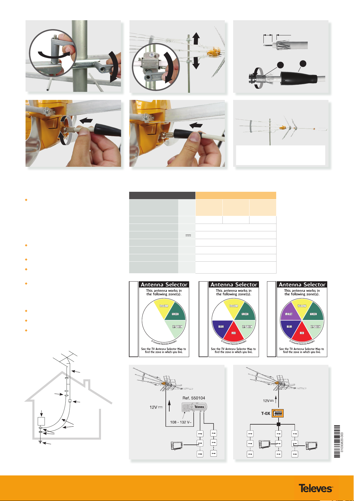
9/32”
(7mm) 1/8”
(3mm)
RS
Once assembled, during nal installation note
that the longer boom is the top part of the
antenna, as indicated in this picture.
* The gain is automatically
adjusted according to the level
of output.
La ganancia varía
automáticamente en función
del nivel de salida.