Telex ACS-101 User manual

Telex
Instruction Sheet
General Description
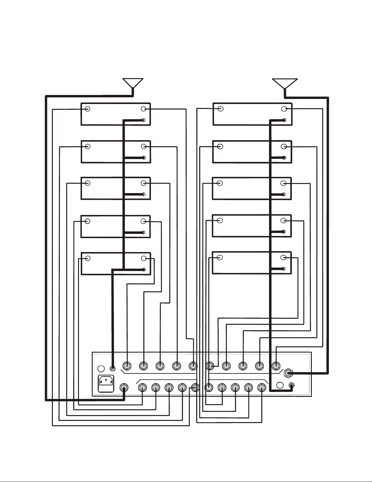
The ACS-101 (Antenna Combiner Splitter 10 to 1) is an
amplified and filtered broadband splitter-combiner. It
allows up to 10 base stations to use only one transmit
and one receive antenna.
The antenna combiner section contains innovative
hybrid coupling, amplifying and matching technol-
ogy to combine 10 transmitters to 1 output with
very low intermod distortion.
ACS-101 Product Features:
The antenna splitter section has broadband input fil-
tering and amplification to maintain signal levels
through the splitters. High output isolation between
ports is also achieved.
The industrial strength power supply of the ACS-101
supplies voltage and current to two outputs on the prod-
uct. Each output can supply up to 5 Amps at 12 VDC.
·Ideal for use with BTR-1, BTR-500, BTR-600, BTR-700 wireless intercom systems.
·Two power outputs to supply up to 10 transceivers (5 on each daisy-chain run)
which makes large systems easier to implement.
·Standard IEC 320 power input connector
·115 VAC or 230 VAC operation
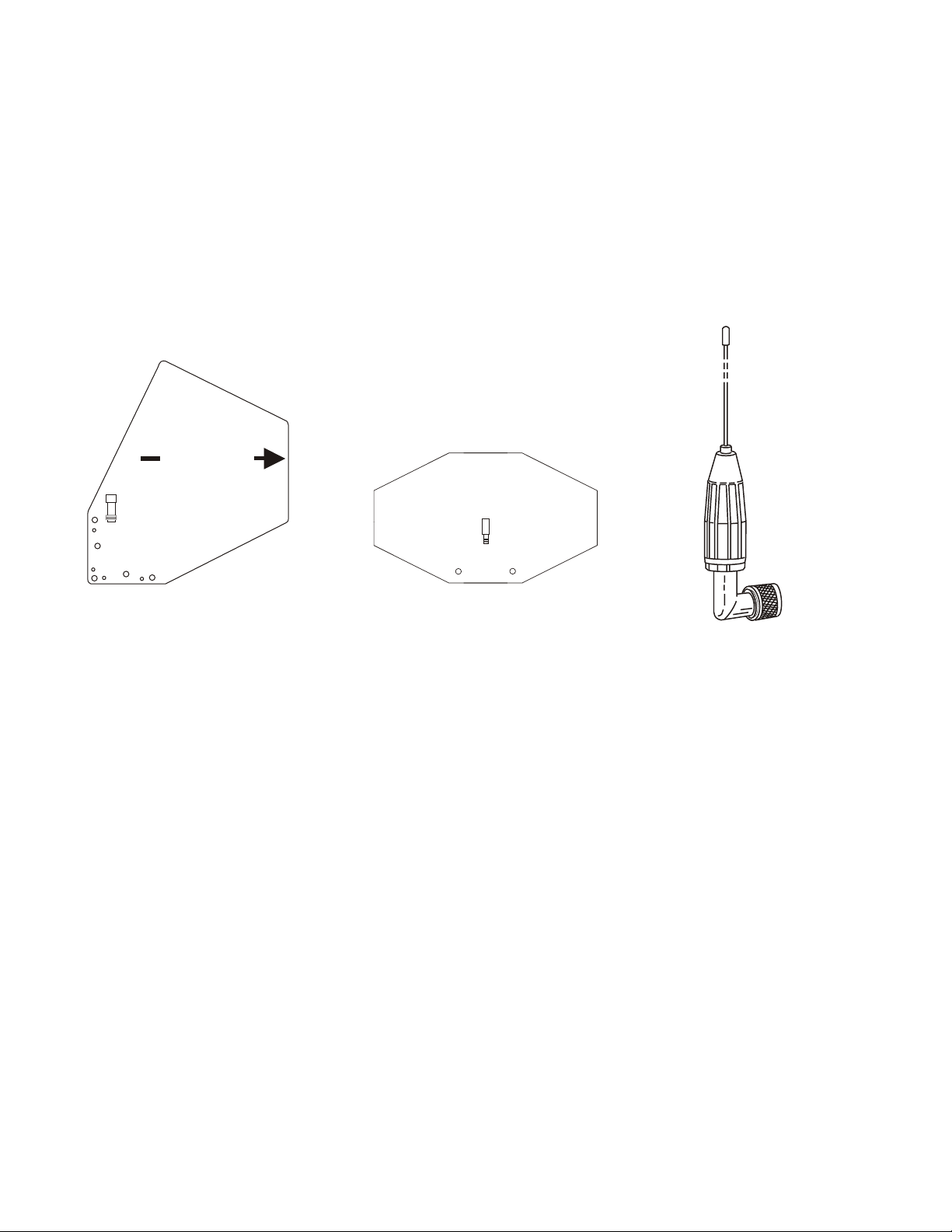
·High-Quality TNC connectors for consistent impedance across the entire frequency range.
·Rack mount brackets included for 19" (482.6 mm) rack
-1-
TELEX COMMUNICATIONS, INC. 12000 Portland Ave. South, Burnsville, MN 55337
®
SPECIFICATIONS
Overall
Antenna Connectors .........................................................................................................................Standard TNC Receptacles
AC Input Power .......................................................................................................................100 - 120 VAC, 60 Hz, 6A max
AC Input Fuse................................................................................................................................................10 A, 250 V, 3AG
DC Output Power.........................................................................................................................12 VDC, 5 A for each output
DC Output Jacks...........................................................................................................................Two, 5.5mm x 2.1 mm Jacks
DC Output Fuses..............................................................................................................................5 A, 250 V, 5mm x 20 mm
Size ...................................................................................H: 3.50" (88.9 mm) x W: 16.75" (426 mm) x D: 14.63" (372 mm)
Weight ....................................................................................................................................................10 lbs., 4 oz., (4.65 kg)
Antenna Splitter
Frequency Range ................................................................................................................................................614 - 746 MHz
Output IP3..................................................................................................................................................Greater than 30 dBm
Net Gain................................................................................................................................................................. 0 dB Typical
Noise Figure .....................................................................................................................................................Less than 4.5 dB
Minimum Isolation......................................................................................................................20 dB between adjacent ports.
Greater than 20 dB between non-adjacent ports
Antenna Combiner
Frequency Range ................................................................................................................................................470 - 608 MHz
Net Gain...........................................................................................................................................................0 dB (Maximum)
Noise Figure..........................................................................................................................................................10 dB Typical
Output IP3.......................................................................................................-55 dBc @ + 17 dBm input on each transmitter
ACS-101
AMPLIFIED BROADBAND UHF
COMBINER-SPLITTER PN 803984

Connections, Fuses and Indicators
-2-
1. Power/Overheat Light -
Green - The unit has power.
Red - The unit has overheated and the combiner amplifiers
have shutdown. There is a sensor on the combiner amplifier
heatsink that senses if the heat rises above 75º C (167 F).
2. DC Outlet Fuses - 5 Amp, SlowBlow, 250 VDC. Size is 3AG.
3. IEC Power Inlet with Fuse - IEC-320 power inlet with a 10
Amp, 250 VDC Fuse. Size is 5mm by 20mm.
4. DC Power Output Jacks - Threaded 5.5mm x 2.1mm Jacks. 12
VDC up to 5 Amps is available at each jack.
5. Receive Antenna Jack - This TNC female connector is where
the receive antenna connects.
6. Receive Splitter Jacks - These ten TNC Female connectors are
the outputs for the receive signals. NOTE: All unused jacks
should be terminated with 50 Ohm loads (See accessories
listed at the end of this document).
7. Transmit Combiner Jacks - These ten TNC female connectors
are the inputs for the transmitters.
8. Transmit Antenna Jack - This TNC female connector is where
the transmit antenna connects.
CS-
A01
1
UHF Antenna Splitter/Combiner
POWER - GREEN
OVERHEAT- RED
RadioComTM
by TelexR
1
Figure 1 ACS-101 Front View
Figure 2
ACS-101 Rear View
TRANSMIT
ANTENNA
FUSE
5A SLOW BLOW
DC OUT
12V 5A
FUSE
5A SLOW BLOW
DC OUT
12V 5A
RECEIVE
ANTENNA
TRANSMIT
RECEIVE
8
24
3524
7
6

-3-
System Configuration
Figure 4 illustrates the typical system configuration
using the ACS-101 to support 10 BTR-1 base stations.
TRANSMIT
ANTENNA
FUSE
5A SLOW BLOW
DC OUT
12V 5A
FUSE
5A SLOW BLOW
DC OUT
12V 5A
RECEIVE
ANTENNA
TRANSMIT
RECEIVE
Rx Tx
Power
Rx Tx
Power
Rx Tx
Power
Rx Tx
Power
Rx Tx
Power
RECEIVE
ANTENNA
TRANSMITTER
ANTENNA
Rx Tx
Power
Rx Tx
Power
Rx Tx
Power
Rx Tx
Power
Rx Tx
Power
Rx Tx
Power
Figure 4
System Configuration

Antenna Requirements
The ACS-101 may be used with a variety of anten-
nas. For best results, use a pair of ALP-450 direc-
tional log periodic antennas (See Figure 5) or, the
ALP-600 Bi-directional log periodic antenna (See
Figure 6).
Good results may also be obtained with 1/2 wave
antennas (See Figure 7). All antennas are sold sepa-
rately.
When using 1/2 wave antennas, we recommend us-
ing the higher frequency model when the receivers
operate in more than one band. If the receivers are
more than one band apart, such as yellow and
white, we strongly recommend using the ALP-450,
or ALP-600 depending on the application.
Place the ACS-101 with antennas in a location that
is in direct view of the beltpacks for best results.
-4-
T
THIS END TOWARD TRANSMITTER
ALP-450
ex
el
R
Telex
Figure 5
ALP-450
Figure 6
ALP-600
Figure 7
1/2 Wave Antenna

Antenna Placement
for Optimum Range and Rack Mounting
For maximum range and when rack mounting, the
antennas must be remotely located.
The ALP-450 and ALP-600 antennas come com-
plete with a variety of mounting hardware and 10
feet (3 meters) of low loss coaxial cable. A combi-
nation mounting bracket with 10 feet of coaxial ca-
ble is available for 1/2 wave antennas (Model No.
AB-2).
Antennas should be placed in a location with a clear
“signal path” to the beltpacks. This “path” should
be as short and free of obstructions as possible. Ob-
structions, such as walls ceilings, and metal objects,
will reduce range and performance.
Rack Mounting
·Rack mount brackets are supplied with the
ACS-101. To attach the brackets, proceed as fol-
lows:
·Align the rack mount bracket with the holes on
the side of the unit. See Figure 8.
·Install flat head machine screws in two holes.
Tighten securely. Repeat on the other side of the
unit. For best alignment, perform the above
steps while the unit and rack brackets are set-
ting on a flat surface.
·Insert the unit into a 19" rack enclosure and in-
sert four screws (not supplied) in each corner of
the rack mount brackets and secure.
Coax Cable
For best results, it is recommended that cable losses
be kept under 4 dB. (Every 3 dB of signal loss results
in a system operating distance reduction of 25%.
See the accessories section of this manual for spe-
cial low loss cable assemblies.
-5-
Figure 8
Rack Mount Brackets

ACS-101 Accessories and Replacement Parts
ALP-600
480-800 MHz Bi-Directional log periodic antenna
Includes mounting hardware and 10 feet (3 meter)
coaxial cable with TNC connectors
Order No. 878896
Low loss coaxial antenna cables with
TNC connectors
TP-2 50 OHM/TNC dummy load
(For unused outputs)
Part No. 650095
AB-2
Bracket for 1/2 wave Antenna with 10 ft. of coax
Part No. 71138000
ALP-450
450-900 MHz Log Periodic Antenna
Includes mounting hardware and 10 feet (3 meter)
coaxial cable with TNC connectors
Order No. 71147000
1/2 wave Antenna
(CLA-X)
-6-
Telex
T
THIS END TOWARD TRANSMITTER
ALP-450
ex
el
R
MICROPHONE STAND
MOUNTING
Model Length Order No.
CXU-10 10 Ft. (3 meter) 690419
CXU-25 25 Ft. (7.6 meter) 71151-025
CXU-50 50 Ft. (15 meter) 71151-050
CXU-75 75 Ft. (23 meter) 71151-075
CXU-100 100 Ft.(30 meter) 71151-100
Model No. Part No. Band Color Frequency
CLA-1 870658-1 Blue 520-565 MHz
CLA-2 870658-2 Yellow 565-615 MHz
CLA-3 870658-3 Red 615-660 MHz
CLA-4 870658-4 White 660-690 MHz
CLA-5 870658-5 Green 690-725 MHz
CLA-6 870658-6 Orange 725-760 MHz
CLA-10 870658-10 Tan 470-518 MHz
CLA-11 870658-11 Pink 515-548 MHz
CLA-12 870658-12 Brown 542-575 MHz
PRINTED IN U.S.A.
Copyright© 2004 by Telex
TELEX COMMUNICATIONS, INC.
All rights reserved
July 2004
Table of contents
Other Telex Cables And Connectors manuals