Telguard TG-7 Series Troubleshooting guide
© 2022 Telguard. Telguard and the Telguard Logo are registered trademarks of
Telular Corporation | Telular is a business unit of AMETEK, Inc. All Rights Reserved.
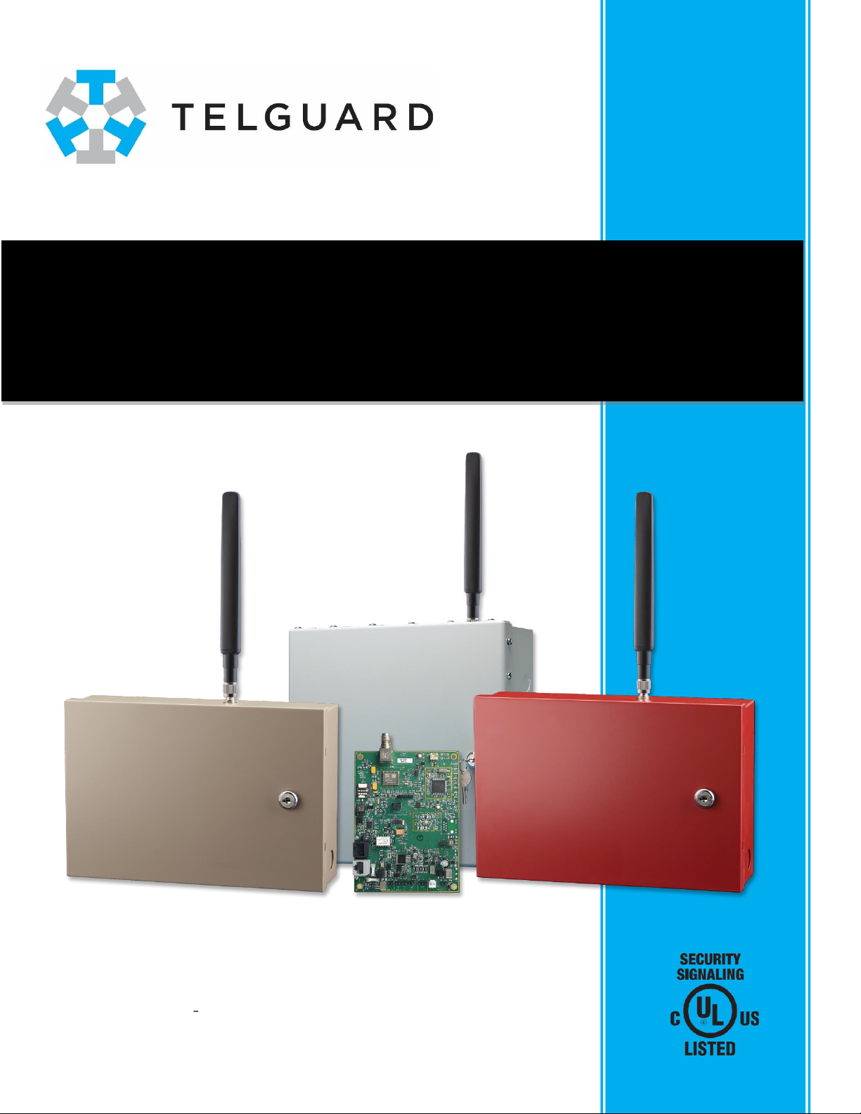
Telguard TG-7 Cellular Series
Installation & Operating Guide
for models TG-7, TG-7FS, TG-7A, and TG-7UB
COMPANY CONFIDENTIAL
For use by TELGUARD®customers only.
Distribution to other parties strictly prohibited.
January 3, 2022
Part Number 56053501 Rev A

TG-7 Cellular Series Installation & Operating Guide i 56053501 Rev A © 2022 Telguard
Important Note
The registration form must be completed before leaving for the job site to install the Telguard
product. Use our dealer portal at www.telguard.com to register the unit in real time.
Foreword
Dealers purchase Telguard® cellular communicators for the quality, features and total value they
represent. The Telguard TG-7 Cellular Series devices (TG-7, TG-7A, TG-7FS, and TG-7UB) are UL
Listed for Commercial Burglary and, depending on the model, Commercial Fire systems. The Telguard
TG-7 models may be used in Retail or Commercial Burglary/Fire systems as the sole, primary or
secondary communication path.
Technical Support
Technical support for all Telguard products is available:
Toll Free: 800-229-2326, option 9
Monday Saturday, 8am 8pm ET
About this Manual
This manual assumes that you have basic security system installation skills such as measuring
voltages, stripping wire, properly connecting wires together, connecting wires to terminals, and
checking phone lines. It also assumes that you have a familiarity with the proper installation and
programming tasks related to various alarm panels.
The material and instructions covered in this manual have been carefully checked for accuracy and are
presumed to be reliable. However, Telguard assumes no responsibility for inaccuracies and reserves
the right to modify and revise this manual without notice.
It is our goal at Telguard to always supply accurate and reliable documentation. If a discrepancy is
found in this documentation, please send an email message to:
Or, write to:
Telguard Technical Services
3225 Cumberland Blvd
Suite 300
Atlanta, GA USA 30339
NOTE: References in this manual to the TG-7 Cellular Series product should be
construed to apply equally to all models unless otherwise indicated. Similarly, unless
otherwise indicated, all information applies equally to either the AT&T or Verizon
model of any given product. The TG-7UB should be treated as the TG-7, TG-7A, or TG-
7FS product that is being updated; follow the Install instructions provided with the
TG-7UB to upgrade to the new board, then consult this Guide.

TG-7 Cellular Series Installation & Operating Guide ii 56053501 Rev A © 2022 Telguard
Repair and Warranty
If trouble is experienced with the Telguard Cellular Alarm Communicator please contact
Telguard Technical Support for troubleshooting, repair, and (or) warranty information.
The dealer or end user should not attempt any repair to the TelguardCellular Alarm
Communicator. Repair of this equipment should only be referred to qualified technical
personnel.
Telguard will repair or replace (our option) inoperative units for up to two years from date
of manufacture. This excludes damage due to lightning or to installer error. Unauthorized
modifications void this warranty. Not responsible for incidental or consequential
damages. Liability is limited to price of unit. This is the exclusive warranty and no other
warranties will be honored, whether expressed or implied.
An RMA must be assigned before returning product. You may obtain an RMA via phone at
NOTE: RMA number must be on the outside of box or product will not be accepted.
Future Testing and Limitations on Use
The Telguard TG-7 Cellular Series communicator is part of an advanced design alarm
communication system. It does not offer guaranteed protection against burglary and fire.
Any alarm communication system is subject to compromise or failure.
The communicator will not work without power. Electrically powered devices will not
work if the power supply is off for any reason, however briefly.
The cellular radio network, needed to transmit alarm signals from protected premises to a
central monitoring station, may be inoperable or temporarily out of service. Cellular radio
networks are also subject to compromise by sophisticated methods of attack.
This equipment, like any other electrical device, is subject to component failure. Although
this equipment is designed to be long-lasting, the electrical components could fail at any
time.
Due to these limitations, we recommend that if the automatic self-test feature is not
enabled, other arrangements be made with the user to test the system at least once every
three months. Moreover, arrangements should also be made for on-site inspection/test
by a licensed alarm installer at least once each year.
Terms and Conditions for Use of Telguard Product
These Terms and Conditions are a legal contract between you and Telguard for the title to
and use of the Product. BY RETAINING AND USING THE PRODUCT YOU AGREE TO THE
TERMS AND CONDITIONS INCLUDING WARRANTY DISCLAIMERS, LIMITATIONS OF
LIABILITY AND INDEMNIFICATION PROVISIONS BELOW. IF YOU DO NOT AGREE TO
THE TERMS AND CONDITIONS, DO NOT USE THE PRODUCT AND IMMEDIATELY RETURN
THE UNUSED PRODUCT FOR A COMPLETE REFUND. You agree to accept sole
responsibility for any misuse of the Product by you; and, in addition, any negligent or
illegal act or omission of you or your agents, contractors, servants, employees, or other
users of the Product so long as the Product was obtained from you, in the use and
operation of the Product.

TG-7 Cellular Series Installation & Operating Guide iii 56053501 Rev A © 2022 Telguard
INDEMNIFICATION OF TELGUARD
YOU SHALL INDEMNIFY, DEFEND AND HOLD HARMLESS TELGUARD FOR ANY OF THE COST,
I R, YOUR
IN A MANNER NOT CONTEMPLATED BY YOU AND TELGUARD OR INCONSISTENT WITH THE
PROVISIONS OF THIS MANUAL; (ii) IN AN ILLEGAL MANNER OR AGAINST PUBLIC POLICY; (iii) IN A
MANNER SPECIFICALLY UNAUTHORIZED IN THIS MANUAL; (iv) IN A MANNER HARMFUL OR
DANGEROUS TO THIRD PARTIES; (v) FROM CLAIMS BY ANYONE RESPECTING PROBLEMS, ERRORS
OR MISTAKES OF THE PRODUCT; OR (vi) COMBINATION OF THE PRODUCT WITH MATERIAL
MODIFICATION OF THE PRODUCT OR USE OF THE PRODUCT IN AN ENVIRONMENT NOT
PROVIDED, OR PERMITTED, BY TELGUARD IN WRITING. THE PARTIES SHALL GIVE EACH OTHER
PROMPT NOTICE OF ANY SUCH COST OR CLAIMS AND COOPERATE, EACH WITH THE OTHER, TO
EFFECTUATE THIS INDEMNIFICATION, DEFENSE AND HOLD HARMLESS.
WARRANTY and LIMITATIONS
TELGUARD WILL REPAIR OR REPLACE (OUR OPTION) INOPERATIVE UNITS FOR UP TO TWO
YEARS FROM DATE OF MANUFACTURE. EXCLUDES DAMAGE DUE TO LIGHTNING OR INSTALLER
ERROR AS WELL AS UNITS THAT INCORPORATE MATERIAL, OR USED IN A MANNER OR
ENVIRONMENT, NOT SPECIFICALLY AUTHORIZED IN THIS MANUAL. UNAUTHORIZED
MODIFICATIONS VOID THIS WARRANTY. NOT RESPONSIBLE FOR INCIDENTAL OR
CONSEQUENTIAL DAMAGES. LIABILITY LIMITED TO PRICE OF UNIT. THIS IS THE EXCLUSIVE
WARRANTY, IN LIEU OF ALL OTHER WARRANTIES INCLUDING IMPLIED WARRANTIES OF
MERCHANTABILITY, TITLE, DELIVERY, INFRINGEMENT OR FITNESS FOR A PARTICULAR PURPOSE
AND NO OTHER WARRANTIES WILL BE HONORED, WHETHER EXPRESSED OR IMPLIED.

TG-7 Cellular Series Installation & Operating Guide iv 56053501 Rev A © 2022 Telguard
Table of Contents
Important Note i
Foreword i
Technical Support i
About this Manual i
Repair and Warranty ii
Future Testing and Limitations on Use ii
Terms and Conditions for Use of Telguard Product ii
INDEMNIFICATION OF TELGUARD
WARRANTY and LIMITATIONS
General Description and Operation 1
Information Related to Software Settings Fire Systems 3
Information Related to Software Settings Burglary Systems 5
Features 7
Operating Mode 7
Multiple Alarm Format Support 7
Complete Supervision of Communication Path 7
Link Supervision and Standard Line Security 8
Complete Power Supervision 9
Telguard Automatic Self-Test Report 9
Programmable Supervisory Trip Output (STC) Relays 10
Post-Installation Remote Programming 11
Diagnostic and Status LEDs 11
Optional DC Operation (12VDC or 24VDC) 11
Complete Factory Reset Option 11
UL and ULC Compliance 12
Getting Ready 13
Dealer Account Establishment 13
Pre-Installation Checklist 13
PCB Layout 14
Installation 15
Summary 15
Step 1: Register the Communicator 15
Select the Mode of Operation
UL/ULC Commercial Fire Sole Path (Cellular Only Mode) Features
Decide on a STC Trip Output Strategy
Optional Trip Input
Step 2: Physically Install the Communicator in Desired Location 17
Identify Location for Placing the Communicator and Mount
Install Optional TG-PEM Accessory into Enclosure (if using)
Complete All Power-Related Wiring Connections

TG-7 Cellular Series Installation & Operating Guide v 56053501 Rev A © 2022 Telguard
Step 3: Determine Antenna Placement for Best Performance 18
Connect Antenna
Measure Received Signal Strength (RSSI)
Optimizing Antenna Performance
Step 4: Make Communications Connections and Activate 19
Special LED Indications During Activation
Verify Alarm Signal Transmissions Over Cellular Path
Step 5: Connect Supervisory Trip Outputs 20
Reprogram Alarm Panel to Send Proper Code
Check Proper Operation of Supervisory Output
Step 6: Connect Tamper Switch (required for burg/optional in fire-only systems) 21
Mandatory for Commercial Burg Use
Optional Use or As Required by AHJ
Optional: Connect and Test the Trip Input 21
Appendix 1 Connection Guide 23
Wiring Diagrams 23
Telco Connection through the Communicator (Backup or Primary Mode)
Cellular-Only Wiring (When Communicator is Only Path Used)
Cellular-Only Wiring (With Telco Connection Through Second Panel DACT)
Tamper Switch Installation 27
RJ-45 Jack Pin Assignments 28
DC Terminal Strip Pin Assignments 28
Main Terminal Strip Pin Assignments 28
AC Terminal Strip Pin Assignments 29
Compatible Alarm Panels 29
Appendix 2 Troubleshooting Guide 30
LED Indicator Guide Normal Operating Mode 30
Troubleshooting Quick Reference Table 31
LED Indicator Guide RSSI Mode 32
Appendix 3 Commercial Fire Single DACT Installation 33
Cellular Signal Strength 33
Configure Fire Alarm Panel to Use Single Communication Device 33
Appendix 4 Commercial Fire 6-hour Supervision 34
Appendix 5 Compliance with UL and ULC Standards 34
Appendix 6 Detailed Specifications 35
Dialer to Interface Electronics 35
Power Requirements 35
Field Wiring Electrical Ratings
Power Limited Circuits
System Faults Impedance
Digital Cellular Radio and Other Specifications 35
Appendix 7 Accessories 36

TG-7 Cellular Series Installation & Operating Guide 1 56053501 Rev A © 2022 Telguard
General Description and Operation
The Telguard TG-7 Cellular Series communicator is an alarm transmission device that facilitates the
use of the cellular network for the delivery of signals for commercial alarm panels, providing the
following three modes of operation:
•Sole path (Cellular Transmission Only)
•Primary path (Cellular Primary & Telco Backup)
•Back-up path (Telco Primary & Cellular Backup)
Depending on the TG-7 Cellular Series model and configuration (as set in the dealer portal), the alarm
panel will utilize the cellular network as a sole, primary or back-up (secondary) transmission path to
deliver alarm messages. In primary/backup mode, the communicator can use either the cellular or
Telco path to transmit an event from the panel and will fail over to the other path should the primary
become unavailable. In Cellular Only mode (Sole Path), the communicator will not monitor for a Telco
connection and strictly use cellular as the means of communication. The sole path mode also offers
the ability to supervise the connection to meet specific burg and fire requirements. In each case, the
communicator is connected to a panel Telco interface (DACT) with a cable that connects to the
-45 jack. The communicator can also be used as either a Primary or
Secondary Path device when an alternate communications path is connected to another Panel DACT.
In such cases, panel settings determine the alarm reporting path.
When transmitting an alarm signal via cellular, the Telguard communicator obtains its data from the
alarm panel by way of the DACT interface, a process sometimes referred to as dial-capture. The
communicator will obtain all alarm signal information including monitoring station phone number,
account number and all zones for every alarm transmission. The communicator handshakes with the
alarm panel and causes it to transmit the alarm data. The communicator encodes the alarm data and
securely transmits it to the Telguard Communication Center (TCC). The TCC performs a function
similar to a central station receiver and issues the transmission acknowledgment when the last
message in the transmission is received. After decoding and reformatting, the alarm signal is routed
to the desired alarm company monitoring station for action. For installations in Canada, a required
End-to-End Acknowledgment feature shall be enabled. This feature will cause a Radio Failure
Condition when an acknowledgment cannot be relayed from the central station to the communicator.
This feature is optional for the United States.
Two programmable System Trouble Condition (STC) relays provide supervisory trip outputs for
communicator trouble
signal to the alarm panel. Additionally, automatic self-test and Check Status signals are transmitted
exclusively over the cellular network with all Telco line and cellular monitoring, switching and
supervisory functions built in. The communicator supports two power supply options: the
communicator can be plugged into a standard AC outlet (120 volts/60Hz) and will keep a dealer-
supplied battery charged, or the communicator can operate on either 12VDC or 24VDC regulated
power supplied by the connected alarm panel.
Telguard offers the ability to establish an override of the central station telephone and account
numbers stored in the panel by providing alternate central station values in the dealer portal
(telguard.com). This can be useful in situations where the installer codes are not known or the panel
cannot otherwise be reprogrammed. When the communicator is configured with override values, all
signals, whether alarm, trouble, or supervisory, will be sent to the override central station. To be able
to send different types of signals to different locations, the central station data for each type of signal
will need to be programmed into the panel and the override values left blank in the dealer portal. This
will cause the communicator to use the central station values as transmitted by the panel.

TG-7 Cellular Series Installation & Operating Guide 2 56053501 Rev A © 2022 Telguard
The UL Listed equipment at the TCC plays a key role in the operation of every Telguard device. All
Telguard units utilize the TCC due to the panel alarm signal format encoding and decoding
requirements used in packet-data transmissions over the digital cellular network. The TCC also
manages the real-time databases for Telguard accounts and a complete history of every Telguard
transmission information, supervisory trouble information, Check Status information, and automatic
self-test information.
TG-7 Cellular Series communicators come in several versions configured to meet the needs of various
applications, to work either with the AT&T or Verizon networks, and to adhere to the UL and ULC
requirements for burglary or fire systems:
Model
Version
Application
UL/ULC Standards
TG-7
TG-7-A
(AT&T)
Communication for Commercial Burglary
Systems in United States and Canada
UL 1610, ULC-S304
TG-7-V
(Verizon)
Communication for Commercial Burglary
Systems in United States
UL 1610
TG-7A
TG-7A-A
(AT&T)
Communication for Retail and Financial
Commercial Burglary Systems in United States
and Canada
UL 1610, ULC-S304
TG-7A-V
(Verizon)
Communication for Retail and Financial
Commercial Burglary Systems in United States
UL 1610
TG-7FS
TG-7FS-A
(AT&T)
Communication for Commercial Burglary and
Commercial Fire Systems in United States and
Canada
UL 1610, ULC-S304,
UL 864, ULC-S559
TG-7FS-V
(Verizon)
Communication for Commercial Burglary and
Commercial Fire Systems in United States
UL 1610, UL 864
TG-7UB
TG-7UB-A
(AT&T)
TG-7 Cellular Series Upgrade Board for Legacy
TG-7 Cellular Series Communicators for
Commercial Burglary and Commercial Fire
Systems in United States and Canada
UL 1610, ULC-S304,
UL 864, ULC-S559
TG-7UB-V
(Verizon)
TG-7 Cellular Series Upgrade Board for Legacy
TG-7 Cellular Series Communicators for
Commercial Burglary and Commercial Fire
Systems in United States
UL 1610, UL 864
NOTE: TG-7 Cellular Series communicators can be used as either a Primary or Secondary Path
device when an alternate communications path is connected to another alarm panel DACT
connection. In such cases, the panel determines the alarm reporting path.
NOTE: While working in Canada, the communicator may use Rogers Wireless, Bell Mobility, Telus,
or SaskTel cellular networks.
TG-7 Cellular Series Installation & Operating Guide 3 56053501 Rev A © 2022 Telguard
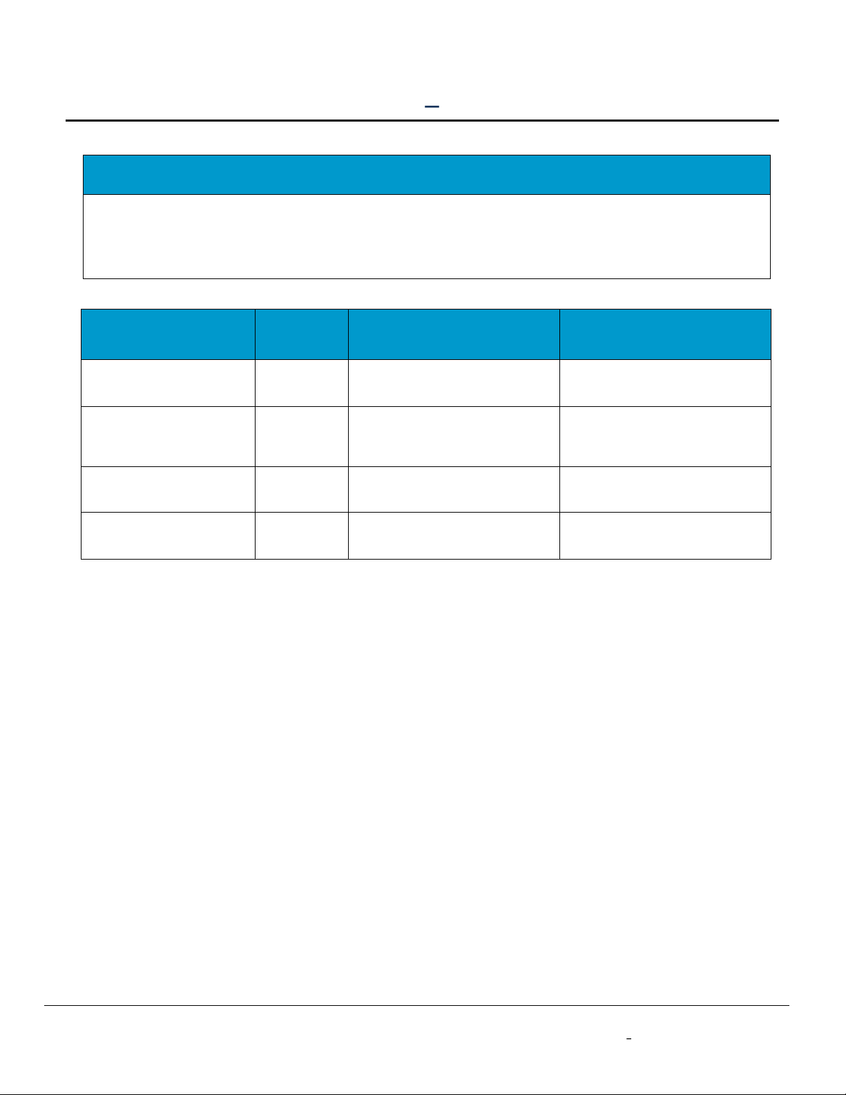
Information Related to Software Settings Fire Systems
NOTICE TO USERS, INSTALLERS, AUTHORITIES HAVING JURISDICTION, OTHER INVOLVED PARTIES
FIRE SYSTEM INSTALLATIONS IN THE UNITED STATES: This product incorporates field-programmable
software. In order to comply with the requirements in the Standard for Control Units and Accessories for
Fire Alarm Systems, UL 864, certain programming features or options must be limited to specific values or
not used at all as indicated below.
Program feature or
option
Permitted
in UL 864
(Y/N)
Available settings
Settings permitted in
UL 864
Link Supervision when
used as a Sole Path
Y
Disabled, 200 seconds, 5
minutes, 60 minutes
200 seconds, 5 minutes,
60 minutes
Automatic Self-Tests
when used with an
alternate communication
path
Y
Disabled, 6 hours*, Daily,
Weekly, Monthly
6 hours
AC Failure Condition
(ACFC)/Low Power
Failure (LPF)
Y
Disabled, any number of hours
up to 24
1 hour, 2 hours, 3 hours
No Service Condition
(NSC) delay
Y
30 seconds, 60 seconds, 3-, 5-,
10- 20-, 30-, 45-, 60-, 1440-
minutes
30 seconds, 60 seconds,
3 minutes
* 6 hours is specified in 2013 and later editions of NFPA 72; the 2010 edition specified 24 hours (daily).
TG-7 Cellular Series Installation & Operating Guide 4 56053501 Rev A © 2022 Telguard
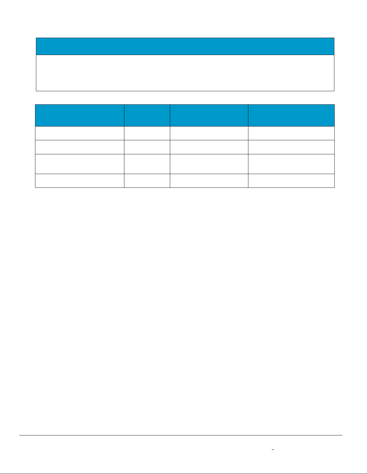
NOTICE TO USERS, INSTALLERS, AUTHORITIES HAVING JURISDICTION, OTHER INVOLVED PARTIES
FIRE SYSTEM INSTALLATIONS IN CANADA: This product incorporates field-programmable software. In
order to comply with the requirements in the Standard for Equipment for Fire Signal Receiving Centres and
Systems, ULC-S559, certain programming features or options must be limited to specific values or not used
at all as indicated below.
Program feature or option
Permitted in
ULC-S559
(Y/N)
Possible settings
Settings permitted in
ULC-S559
Link Supervision
Y
Disabled, 180 seconds
180 seconds
End-to-End Acknowledgment
Y
Disabled, Enabled
Enabled
No Service Condition (NSC)
delay
Y
30 seconds, 60 seconds,
3-, 5- 10-, 20-, 30-, 45-,
60-, 1440- minutes
No more than 60 seconds
AC Failure Condition (ACFC)/
Low Power Failure (LPF)
Y
Disabled, any number of
hours up to 24
1 hour, 2 hours, 3 hours

TG-7 Cellular Series Installation & Operating Guide 5 56053501 Rev A © 2022 Telguard
Information Related to Software Settings Burglary Systems
NOTICE TO USERS, INSTALLERS, AUTHORITIES HAVING JURISDICTION, OTHER INVOLVED PARTIES
BURGLARY SYSTEM INSTALLATIONS IN THE UNITED STATES: In order to comply with the
requirements in the Standard for Central-Station Burglar-Alarm Units, UL 1610 and Standard Line
Supervision, the communicator must meet these requirements:
The TG-7 Cellular Series communicator must be used in one of the following configurations:
•As a primary communicator, single line-200 second supervision; or
•As a secondary communicator line for a DACT (supervision not required). Every 24 hours, a check-in
signal must be sent from the communicator to the central station over the primary dialer and each
communication path shall be monitored for integrity (DACT shall have line monitoring enabled and the
communicator shall have cellular connection supervision enabled).
Additionally:
•When the heartbeat transmission is enabled, the communicator can provide Standard Line Security over
the LTE-M channel.
•The communicator shall be connected to a UL Listed alarm control panel.
•A tamper switch on the communicator shall be connected directly to an input zone on the control panel,
and the zone shall be designated as the zone for Tamper Protection. Tamper wires and all other wires
connecting the communicator to the panel shall be in rigid or flexible metal conduit unless supervised.
•The PPF panel presence failure feature must be enabled if the wiring distance between the panel and the
communicator is greater than 20 feet or the connection is not mechanically protected; setting is
accessible in the online portal.

TG-7 Cellular Series Installation & Operating Guide 6 56053501 Rev A © 2022 Telguard
NOTICE TO USERS, INSTALLERS, AUTHORITIES HAVING JURISDICTION, OTHER INVOLVED PARTIES
BURGLARY SYSTEM INSTALLATIONS IN CANADA: In order to comply with the requirements in the
Standard for Control Units, Accessories and Receiving Equipment for Intrusion Alarm Systems, ULC-S304,
the communicator must meet these requirements (Security Level I or II):
The TG-7 Cellular Series communicator must be used as a Passive communication system line security level P1
(single communication channel) for Security Level I.
Additionally:
•Every 24 hours, a test transmission must be sent to the signal receiving centre over the cellular
communication path.
•The communicator shall be used in conjunction with a ULC or cUL Listed Control Unit/Alarm Panel.
•STC1 and STC2 shall be connected from the communicator to the control panel and designated for
general trouble conditions.
•A tamper switch on the communicator shall be connected directly to an input zone on the control panel,
and the zone shall be designated as the Tamper Protection zone. Tamper wires and all other wires
connecting the communicator to the panel shall be in rigid or flexible metal conduit.
•The PPF panel presence failure feature must be enabled if the wiring distance between the panel and the
communicator is greater than 18m or in different rooms or if the connection is not mechanically protected
in metal conduit; setting is accessible in the online portal.

TG-7 Cellular Series Installation & Operating Guide 7 56053501 Rev A © 2022 Telguard
Features
This section summarizes the key features of Telguard TG-7 Cellular Series communicators.
Operating Mode
The TG-7 Cellular Series is comprised of transmission devices that are installed at protected premises
to provide signal transmission over a cellular connection for alarm systems. The communicator
transmits alarm signals over the nationwide digital cellular network if the telephone line has been
disrupted or compromised, or when set for primary or sole path use of the cellular pathway.
Multiple Alarm Format Support
The Telguard TG-7 Cellular Series communicators support multiple alarm communication formats.
Auto Format Detect feature allows the communicator to adapt to receive any listed format. If the alarm
reason, the communicator will adjust to accept the new format.
NOTE: The communicator auto detection of the panel alarm format.
See Appendix 1 for a list of compatible alarm formats and compliance requirements.
Complete Supervision of Communication Path
The communicator continuously supervises the connection to the alarm panel and the cellular
pathways. If any of these pathways becomes inoperative, the communicator can generate a relay trip
output that can be connected to a zone input of the host alarm panel. These System Trouble
Conditions (STCs) are described below.
Line Fault Condition (LFC)
The communicator monitors voltage on the incoming Telco line. If an inoperative Telco line is
identified, (voltage below 20vdc, on hook) a Telco line fault condition (LFC) is declared. The System
Trouble Condition LED (STC LED) will flash 3 times and the STC relay will trip after a programmable
period of time. Upon Telco restoral, the relay and STC LED are returned to normal.
NOTE: When the communicator is configured to use a sole communications path (cellular), the
Line Fault Condition (LFC) is not applicable.
No Service Condition (NSC)
A no service condition (NSC) occurs when the communicator is unable to register with the cellular
network.
NSC can be configured to trip the supervisory relay output (STC relay) after a programmable period
of time. The STC LED will flash 4 times immediately after losing cellular service and dial-tone will
cease to be provided, independent of the STC assertion and programmed assertion delay. NSC
restoral occurs immediately after cellular service has been acquired.
Radio Communications Failure Condition (RFC)
Radio communications failure condition (RFC) occurs when the communicator is unable to receive a
response from the TCC. When RFC is declared, the STC LED will flash 5 times, dial-tone will cease,

TG-7 Cellular Series Installation & Operating Guide 8 56053501 Rev A © 2022 Telguard
and the STC relay will trip as programmed. Restoral of this condition occurs after 10 minutes or when
a message is received from the TCC.
NOTE: When End-to-End acknowledgment feature is enabled, a message that fails to deliver to the
Central Station will trigger an RFC condition.
Panel Presence Failure (PPF)
Panel presence failure condition (PPF) occurs when the communicator is unable to detect the
presence of the alarm panel. PPF is indicated by the STC LED flashing 7 times. A supervisory report is
generated and sent to the TCC for Central Station delivery upon detection of PPF. Restoral of this
condition occurs when the alarm panel is detected as present for the selected delay time.
NOTE: The factory default for PPF is Disabled and needs to be Enabled for its use. For the PPF
feature to work, Tip, Ring, and the return connections for Tip and Ring must be connected
between the panel and the communicator.
UL/ULC Compliance Note: If the wiring distance between the panel and the communicator is
greater than 20 ft. (18m or in different rooms in Canada) or the connection is not mechanically
protected (metal conduit required in Canada), PPF must be enabled. Since fire systems must
comply with these restrictions (UL 864, ULC-S559), PPF is not required for fire systems.
Control Failure to Communicate (CFC)
The Control Failure to Communicate (CFC) feature allows the Telguard unit to monitor the number of
communication attempts the alarm panel makes over Telco before the unit becomes the main path of
communication. This feature works by monitoring the alarm panel from the time it goes off-hook and
attempts to communicate, to on-hook status, and comes off-hook again. Each change in state by the
alarm panel from off-hook to on-hook to off-hook again is considered an attempt. If this continually
happens for a specified number of times within a specific time period, the unit seizes the line and
takes over as the main communication path for the alarm panel. If the unit goes into CFC, then it will
not allow the panel to communicate via Telco again until the panel has been on-hook for 10
consecutive minutes.
Note that the CFC condition causes the Telguard unit to redirect communications to the cellular
channel, but it is not indicated on the STC LED, nor does it cause the external relays to be tripped.
Note: The factory default for CFC is Disabled and needs to be Enabled for its use. When the unit
is configured as the Sole Path, the CFC function is not applicable.
Link Supervision and Standard Line Security
In order to satisfy UL and ULC requirements, the communicator can enable link supervision at preset
intervals. When this feature is enabled, TG-7 Cellular Series communicators also meet the
requirements for Standard Line Security when used with a UL Listed compatible alarm panel. Once
the communicator is provisioned with the Link Supervision option, the TCC constantly monitors all the
enabled communicator pathways and sends a specific message to the Central Station if a path is
broken or a compromise attempt is made. After the initial account activation has completed, the
installer must verify the Link Supervision by turning off the device and making sure an alarm with the
specific code is delivered.
WARNING: Standard Line Security has only been evaluated between the communicator and the
TCC. It is the responsibility of the installer to verify Standard Line Security from the Listed alarm
panel to the Listed receiver through the communicator as marked on the alarm panel and as
indicated in the manufacturer's installation instructions.

TG-7 Cellular Series Installation & Operating Guide 9 56053501 Rev A © 2022 Telguard
Complete Power Supervision
The communicator can supervise and report status of the backup battery and AC power source when
powered from the AC adapter. It has an integrated control and power component which keeps the
battery charged and is supervised. Furthermore, the communicator can report on
low voltage events when powered from a DC source from the alarm panel.
Low/Missing Battery Condition (LBC)
When using AC as the main power source, the communicator checks the backup battery voltage on
initial power-up and every 60 seconds thereafter. If the battery voltage is less than 11.6 volts, it
an LBC occurs whereby the STC LED blinks twice, and the STC
relay trips. When the battery voltage increases to 12.1 volts, the STC LED and STC relay restore. The
communicator also indicates Low/missing Battery Condition (LBC) when the battery charger fails, or
the battery fails the periodic load test.
AC Failure Condition (ACFC)
AC failure condition (ACFC) is detected immediately when the AC power-driven input from the plug-
in adapter drops below 8 VAC. When this condition is detected, the STC LED blinks once, the Power
LED turns off, and the STC trip output is activated after a preset time (default 2 hours). When AC
power returns to normal (at least 10 VAC), the Power LED turns on immediately and the STC trip
output restores after 60 seconds. When ACFC occurs, you may want to verify both the power at the
outlet and that coming from the adapter.
Low Power Failure (LPF)
If the communicator is being powered through the DC connection, a Low Power Failure condition
(LPF) is detected immediately when the DC power drops below 7.5VDC. When this condition is
detected, the STC LED blinks once, the Power LED turns off, and the STC trip output is activated after
a preset time (2 hours). When DC power returns to normal (8VDC), the Power LED turns on
immediately and the STC trip output restores after 60 seconds.
Dial Tone Failure (DTF)
The communicator provides a telephone interface similar to that of a Telco central office. The
communicator continuously monitors the circuit that provides dial tone to the alarm panel. The
communicator supplies 30VDC by default but can be configured to supply 40VDC, as needed. A Dial
Tone Failure (DTF) occurs when the communicator is unable to provide proper telephone signaling to
the panel (voltage supplied unexpectedly drops). The STC LED will flash 6 times and the STC relay
will trip.
NOTE: This condition will require contacting Telguard Technical Support for resolution.
Catastrophic Failure (CF)
Catastrophic Failure (CF) is any condition that causes the communicator to stop functioning at all
levels. The most common CF is a power failure event with insufficient battery backup. The STC1 and
STC2 trip outputs are activated, and the visible indication is loss of all LED activity.
Telguard Automatic Self-Test Report
The automatic self-test signal schedule is programmable as prescribed when the communicator is
registered. The Central Station receives the automatic self-test report in the same format that the

TG-7 Cellular Series Installation & Operating Guide 10 56053501 Rev A © 2022 Telguard
alarm panel normally uses for communication over the Telco line. The self-test code and testing
frequency are set during registration and can accommodate any code the Central Station expects.
The TCC captures all current and historical data pertaining to the operation of the communicator
when it processes the automatic self-test signal. This data contains current operational status (C.O.S.)
of the communicator such as "All OK", "AC fail condition", "low/missing battery condition", or any
combination of identified trouble conditions as well as the current cellular signal strength. In addition,
the data also contains historical data for supervisory events that occurred since the last self-test or
Check Status report signal was transmitted. This data includes the number of occurrences of AC fail
conditions, low battery conditions, line fault conditions, and no cellular service conditions. This
additional information is available by visiting www.telguard.com (dealer log-in credentials required).
Although the communicator has the capability for an automatic periodic self-test, a separate feature is
provided for determining the current operational status of every Telguard communicator. This feature
is called Check Status and is used to provide real-time operational status for the communicator on-
demand. It is useful in resolving STC events that are reported by the alarm panel to the Central
Station. Check Status is available via www.telguard.com (dealer log-in required).
Check Status causes the communicator to upload current operational status data and historical data,
just as the automatic self-test described above, except that the resulting status is held in the Telguard
database at the TCC for review and is not forwarded to the Central Station.
Programmable Supervisory Trip Output (STC) Relays
The communicator has two supervisory relay trip outputs available (STC1 normally open and STC2
normally closed) and both are energized in a powered-up state when no system troubles exist. This
enables a supervisory trouble code to be transmitted to the Central Station when connected to an
-hour instant input zone. The trouble conditions that trigger the STC relays are
programmable via telguard.com (dealer log-in required) to meet virtually any installation requirement.
Note: If using a supervised zone to monitor for the STC relay, please make sure that you follow
resistance requirements of the alarm panel for supervision. Refer to manual supplied with the
panel for further guidance.
The following supervisory features or combination of features are programmable to trip the STC
relays in order to meet a variety of installation requirements:
•AC Failure Condition (ACFC) or Low Power Failure condition (LPF)
•Low or missing Battery Condition (LBC)
•No Service Condition (NSC)
•Radio Failure Condition (RFC)
•Line Fault Condition (LFC)
The following system trouble features are embedded in the communicator for tripping the STC relays
and cannot be changed:
•Dial Tone Failure (DTF): insufficient voltage on connection to panel DACT
•Communicator not activated at TCC: communicator requires activation for use
•Catastrophic Failure (CF): all power is lost
•Transmit Disable command received from TCC: used when a runaway dialer situation is
detected or by Customer Service
UL/ULC Compliance Notes:
•In Fire installations, STC2 (normally closed) cannot be used for communicating with the
alarm panel; only STC1 (normally open) can be used.
ULC Compliance Notes:
•For Commercial Burglary installations, STC1 shall be connected to the panel's 24hr zone
and shall be designated only as Low Power Condition. Other failure conditions shall be
triggered through STC2 and shall be treated as general trouble conditions.
•For Commercial Burglary installations which use the optional TG-PEM accessory, consult
the TG-PEM Manual for the configuration of STC1.

TG-7 Cellular Series Installation & Operating Guide 11 56053501 Rev A © 2022 Telguard
•For all installations in Canada, the End-to-End Acknowledgment feature is required. When
an acknowledgment for a message cannot be relayed from the central station to the
communicator, the Radio Failure Condition will be triggered.
•In Canada, TG-7 Cellular Series devices are suitable for use in Security Level 1 applications.
Post-Installation Remote Programming
To continue to meet compliance requirements, once a unit is installed it cannot be remotely
reprogrammed or receive updated firmware from Telguard Technical Support without manual on-site
action. To change the device settings or accept updated firmware, follow these steps:
•Locate and press the RSSI button on the communicator, holding it for at least 5-7 seconds.
•LED 5 will flash, indicating that a message has been sent to initiate a Maintenance Window.
•The maintenance window will last for 10 minutes after receipt of the device message.
•Log into the telguard.com dealer portal and make the necessary configuration changes to the
device, within the observed maintenance window (10 minutes).
•No device configuration changes can be made outside of the maintenance window.
NOTE: All alarm functions and transmissions will continue to operate during the Maintenance
Window. The alarm system should be placed in test mode with the central station.
Diagnostic and Status LEDs
Seven active LEDs are provided as a useful aid during installation and give installers an immediate
visual indication of system status. The LEDs serve as indicators for activation, system trouble
conditions, power, and communication indicators. They can also provide a signal strength indication,
similar to the signal strength bars on a cellular phone. See Appendix 2 or the installation section for
details.
Optional DC Operation (12VDC or 24VDC)
The TG-7 Cellular Series communicators can be operated solely by DC power provided by an alarm
panel. This eliminates the need for a separate AC outlet at the protected premises. To use, connect
12VDC or 24VDC regulated power from the p
communicator. LED 8 will illuminate to indicate the communicator has a valid power source. The
provided AC adapter should NOT be used when powering the communicator from the alarm panel.
NOTE: When using TG- -
PEM and the TG-PEM Telguard Power connection should go to the DC input on the communicator.
See Installation Guide for the TG-PEM for more details.
NOTE: When using DC power from an alarm panel (with or without TG-PEM), the communicator
should not be connected to an AC power source or to a battery.
powers the communicator when the panel loses AC power. Be sure to account for this load when
determining how to supply power to the communicator.
Complete Factory Reset Option
A special function within the TG-7 Cellular Series communicators allows you to perform a complete
Factory Reset on the unit. This reset will change all unit settings back to a factory default
configuration.
NOTE: Never attempt to do a Complete Factory Reset on an active account because the unit will
need to be re-activated.

TG-7 Cellular Series Installation & Operating Guide 12 56053501 Rev A © 2022 Telguard
To begin the factory reset, follow these steps:
•Power cycle the device. For the first three seconds after power up, all LEDs will be lit solid.
•While the unit shows this pattern, press and hold the RSSI button. After 15 seconds of button
press, the LEDs will begin to sequentially turn on and off in a cascading pattern, indicating the
factory reset is taking place.
•Release the RSSI button. After the factory reset concludes, the LEDs will go back to normal
status.
UL and ULC Compliance
The TG-7 Cellular Series communicators are certified as complying with UL and ULC Standards for
Commercial Fire and Commercial Burglary installations. The chart on Page 1 shows the associated UL
and ULC Standards. Certificates of Compliance are available at telguard.com.
UL/ULC Compliance Note: The alarm panel must also be UL, ULC, or cUL Listed for commercial
fire and/or commercial burglary use as appropriate.
ULC Compliance Notes:
•For Commercial Fire installations in Canada, the radio frequency warning label (supplied)
must be affixed to the outside front cover of the communicator to maintain compliance.
•Communicator is suitable for Active communication in fire installations (ULC-S559) and
for Passive Level 1 (P1) Line Security in burglary installations (ULC-S304).

TG-7 Cellular Series Installation & Operating Guide 13 56053501 Rev A © 2022 Telguard
Getting Ready
The communicator can only be activated when all necessary accounting information has been added
to the TCC customer database (i.e., the unit has been registered). The database includes information
about the customer account, unit location, and system test plan information.
Dealer Account Establishment
A Dealer Account must be established prior to registration of any Telguard unit. This can be
accomplished by visiting telguard.com and completing
Signup This is a one-time event and an acknowledgment from Telguard Customer Service will
include a Dealer Account Number that will be used for all Telguard Digital registrations. Telguard
units can be registered and activated once the Dealer Account has been established.
Pre-Installation Checklist
Before attempting to connect the communicator to the alarm panel, please make sure you have all the
proper parts prior to going to the job site. The following items are shipped with each TG-7 Cellular
Series product:
•Telguard Cellular Communicator
•Cellular Antenna
•Antenna Extension Cable and Mounting Bracket
•AC Power Adapter
•Battery Connection Cable
•Telco Connection Cable
•Pluggable Screw Terminal Blocks (2-, 2-, 3-, & 6- position)
•Enclosure Key
•Quick Install Guide
•Frequency Warning Label to be applied for installations in Canada (AT&T models only)
•Tamper Switch Easy-Attach Assembly (TG-7 and TG-7A only or when purchased as an accessory)
Note: When upgrading an existing communicator using the TG-7UB, continued use of some existing
items is necessary. See the instructions provided with the TG-7UB for further details.
PRINTED CIRCUIT BOARD (PCB)
INSIDE METAL ENCLOSURE
TERMINAL
BLOCKS
LTE
ANTENNA
MOUNTING
BRACKET
ENCLOSURE
KEY
AC ADAPTER
12FT ANTENNA
CABLE
TELCO CABLE
BATTERY
CONNECTOR

TG-7 Cellular Series Installation & Operating Guide 14 56053501 Rev A © 2022 Telguard
The following items may be needed and are not included with the communicator:
•Screws or nails for mounting the communicator enclosure and antenna to the wall
•Solid or stranded electrical wire for connecting the STC relay outputs, trip input, or tamper to the
alarm panel. The terminal blocks can accommodate solid or stranded 16 to 22 gauge wire.
•Conduit and connectors for protecting wiring
•Lead acid backup battery (7Ah recommended/4Ah minimum) when installation will use the AC
power adapter
Finally, certain installation and testing tools may be needed or helpful:
•Screwdrivers for mounting and making connections
•Standard telephone or lineman's butt-set for verifying communication between the panel and the
communicator
NOTE: The communicator registration must be completed in advance to avoid installation delays
PCB Layout
D1
D2
D3
D4
D5
D6
D7
D8
RSSI
BUTTON
RESET
BUTTON
RJ-45
DACT JACK
for PANEL
CONNECTION
EARTH
GROUND
RJ-45
PHONE JACK
for TELCO
CONNECTION
Other manuals for TG-7 Series
5
This manual suits for next models
4
Table of contents
Other Telguard Cell Phone manuals

Telguard
Telguard TG-1 Express CDMA User manual

Telguard
Telguard TG-4 User manual

Telguard
Telguard Dual Path Series Troubleshooting guide

Telguard
Telguard TG-1 Express CDMA User manual

Telguard
Telguard TG-1 Express CDMA User manual

Telguard
Telguard TG-1 Express CDMA User manual

Telguard
Telguard TG-SCI Plus User manual

Telguard
Telguard TG-7 Series User manual

Telguard
Telguard TG-4 User manual

Telguard
Telguard TG-1 Express CDMA User manual


