Telguard TG-1 Express CDMA User manual

Quick Install Guide
TG-1 Express CDMA
June 5, 2014
COMPANY CONFIDENTIAL
For use by TELGUARD®customers only.
Distribution to other parties strictly prohibited.

56046902 2 © 2014 Telular Corporation
Foreword
The Telguard model TG-1 Express CDMA cellular alarm communicator is UL Listed for
Household Fire systems and Household Burglary systems. This means that the TG-1
Express CDMA may be used in Household Burglary systems, Household Fire systems
or combined Household Burglary & Fire system as the primary communication path.
Telguard Support
Telular Support for all Telguard products is available Toll Free at 800-229-2326
Option 1 for Registration and Customer Service
Option 5 for Sales
Option 9 for Technical support
Email Support is provided by:
[email protected]: Customer Service and Registration
[email protected]: RMA requests
Telular also hosts two sites for public and dealer access:
www.telguard.com: public access site.
www.TelguardOnline.com: dealer-only access.
About this Guide
The material and instructions covered have been carefully checked for accuracy
and should provide enough guidance for a successful installation.
Note: If more detailed information is required, you may download the full
version of the Installation Manual from our websites:
www.telguardonline.com or www.telguard.com.
Terms and Conditions
“Telular Terms and Conditions of Sale” as well as “Telular Master Reseller Agreement
– Telguard Services” are applicable. For more information, visit the dealer portal at
www.TelguardOnline.com or contact Customer Service at 800-229-2326, option 1.
56046902 3 © 2014 Telular Corporation
Repair and Warranty
Repair of Telguard equipment should only be referred to Telular. Telular will repair or
replace (our option) inoperative units for up to two years from date of manufacture.
This excludes damage due to lightning, unauthorized modifications or installer
error. Telular is not responsible for incidental or consequential damages.
If a Telguard unit needs to be returned for repair, please return the product to the
distributor that the unit was originally purchased from. The distributor will contact
Telular to obtain an RMA based on the unit’s warranty eligibility.
Units returned for repair that are out of the warranty period or do not meet warranty
criteria will be subject to a minimum repair charge.
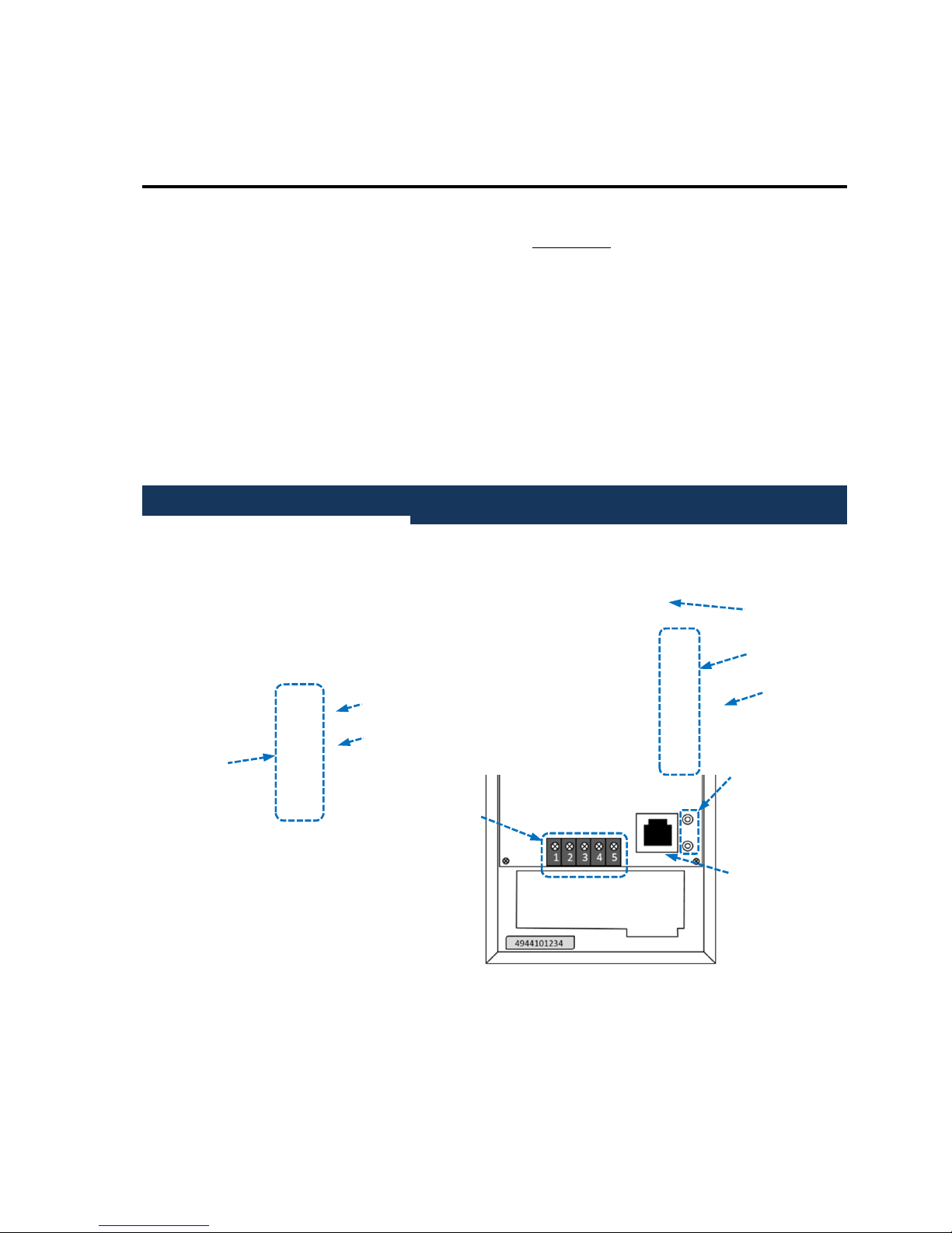
General Description
LED
Indicators
Reset Pinhole
Button
RSSI Button
Terminal Block
1 = STC
2 = STC
3 = TRIP IN
4 = GND
5 = PWR
Serial Number
LED Indicators
RSSI Button
Tip & Ring Posts
RJ-45 Connector
(to Panel

56046902 4 © 2014 Telular Corporation
Features
Multiple Alarm Format Support
The default program setting of the Telguard TG-1 Express CDMA is for Auto
Detection of the panel’s alarm format. Auto Detection allows the Telguard to adapt
to receive any listed format. For a complete list of acceptable formats please refer to
the full Installation manual available at www.TelguardOnline.com.
Panel-Supplied Power
The Telguard TG-1 Express CDMA can usually be powered from the panel to which it
is connected. It averages 45mA consumption while idle at 12V. Simply supply the
Auxiliary power output from any voltage compatible (6.2V to 17V) panel.
Single Line Interface Cable (SLIC)
To further simplify installation, the TG-1 Express CDMA can use existing connections
within the RJ-45 connector for power and STC connections.
Pin
Wire Color
Assignment
1
Gray
R1
2
Orange
GND
(DC
-
)
3
Black
STC
4
Red
R (Ring)
5
Green
T (Tip)
6
Yellow
STC
7
Blue
PWR (DC+)
8
Brown
T1
Diagnostic and Status LEDs
Seven LEDs are provided as a useful aid during installation giving installers an
immediate visual indication of the Telguard status. The LEDs will toggle between
System Status and Signal Strength indication by use of the RSSI button. Status Mode

56046902 5 © 2014 Telular Corporation
displays activation, system trouble, and communication statuses, while RSSI Mode
shows the signal strength reading—similar to the signal strength bars on a phone.
Complete Supervision
The TG-1 Express CDMA continuously supervises for specific trouble conditions.
Upon configuration, it can generate a relay trip output that can be connected to a
zone input of the host alarm panel or used to activate remote annunciation devices.
No Service Condition (NSC): Declared when the Telguard is unable to register
with the cellular network or the signal strength drops below -114 dBm.
Radio communications Failure Condition (RFC): Declared when Telguard is
unable to transmit over the cellular network even with acceptable signal
strength. RFC is cleared when communication is restored.
Panel presence failure condition (PPFC): Declared when the Telguard is
unable to detect the presence of the host alarm panel. PPFC is restored
immediately after the connection to the panel is restored and maintained for the
delay period.
Dial Tone Failure (DTF): Declared when the 30V supply circuit that provides dial
tone drops to 20V or less while the alarm panel is on-hook. This condition
requires contacting Technical Support for resolution.
Catastrophic Failure (CF): Any condition that causes the Telguard to stop
functioning at all levels, most commonly because of power failure. If power is
connected properly to the unit when a CF occurs, please contact Telguard
Technical Support for resolution.
Installation
Step 1: Register the Telguard Unit for Service
The registration form must be completed before leaving for the job site to install the
Telguard product. The registration form may be completed by:
Online Dealer Portal – www.telguardonline.com
Online Form – www.telguard.com

56046902 6 © 2014 Telular Corporation
Registrations completed via www.telguardonline.com are automatically entered into
the Telguard database. Registrations submitted on www.telguard.com require
manual entry.
Note: During high traffic periods, some cellular network providers may
experience a delay in activation for up to 30 minutes. It is important that you
register the Telguard device prior to leaving for the job site to ensure that
the TG-1 Express CDMA is fully functional when installed.
Step 2: Locate Unit and Measure Signal Strength (RSSI)
Pick a spot next to the alarm panel where you think the Telguard will be mounted
and place the unit down temporarily in that spot. With the alarm panel powered off,
connect to the Telguard unit using either the GND and PWR connections from the
terminal block or the orange (GND) and blue (PWR) leads from a standard RJ-45
connector. Reconnect the alarm panel’s power supply, and ensure that the PWR
indicator (LED 8) on the TG-1 Express CDMA is illuminated.
Connect the antenna to the antenna port and press the RSSI button on the side of
the unit to put the LEDs into RSSI display mode. When you have a found a location
that provides 2 ½ bars (see table below) or more, install the mounting screws and
attach the TG-1 Express to the mounting screws. Press the RSSI button again to
return the LEDs to normal mode.
RSSI
Value Illuminated LEDs RF dBm
N
SC
LED 5 = flash, LED 4
-
2 = off
n/a
1
LED 5 = on, LED 4
-
2 = off
≤
-
111 dBm
1½
LED 5 = on, LED 4 = flash
LED 3-2 = off -110 dBm
2
LED 5
-
4 = on, LED 3
-
2 = off
-
100 dBm
2½
LED 5
-
4 = on, LED 3 = flash
LED 2 = off -90 dBm (Minimum)
3
LED 5
-
3 = on, LED 2 = off
-
80 dBm
3½
LED 5
-
3 = on,
LED 2 = flash -70 dBm
4
LED 5
-
2 = on
-
60 dBm

56046902 7 © 2014 Telular Corporation
Note: Optimum performance can usually be found at the highest point within
a building with the fewest number of walls between the Telguard’s antenna
and the outside of the premises. Avoid mounting the Telguard’s antenna near
other electronic devices to avoid interference.
Step 3: Program, Activate & Transmit Alarms
When powered on, the Telguard will attempt to get provisioned by the CDMA
network. During this process, LED #5 will go into a fast flashing pattern, which could
last up to 60 seconds. Confirm the Telguard has been provisioned by the CDMA
network by verifying LED #5 is off. If instead of turning off, LED #5 begins to slow
flash, the provisioning process has failed.
Installation Tip: To reattempt the Cellular provisioning, press and hold the
RSSI button for five seconds until you see the fast flashing pattern on LED #5.
If the unit continues to fail provisioning, call Telguard Technical Support.
After the unit is provisioned by the Cellular network, it will be ready for activation.
From the panel, initiate a signal to be transmitted by the TG-1 Express CDMA. During
the processing of the first alarm signal the Telguard will transmit all of the necessary
parameters to the Telular Communication Center (TCC). Upon validation by the TCC,
the unit will activate. Once the unit activates it will begin operating in normal mode;
LED #1 will be on solid.
The first alarm is used only to activate the Telguard unit. The first alarm will NOT be
transmitted to the central station. Trip several alarms on the alarm panel and verify
that the central station received them by calling the central station operator.
Step 4: Connect the Supervisory Trip Output
The Telguard provides the host alarm panel with one supervisory trip output for
reporting a Telguard system trouble code to the central station. The supervisory trip
outputs are programmable remotely via the www.telguardonline.com site or locally
with a butt-set.

56046902 8 © 2014 Telular Corporation
Check for proper operation of each programmed supervisory output by causing it to
trip the alarm panel and be sure the LED illuminates and that the STC relay trips.
Step 5: Connect and Test the Trip Input (optional)
In addition to the interface to the alarm panel, a single trip input may be connected
to the terminal block of the TG-1 Express CDMA. When the input is tripped, a
supervisory message is sent to the central station via the Telguard Communications
Center. The functionality of the Trip input can be customized via the
www.telguardonline.com site or by a Telguard Customer Service representative.
Step 6: Complete the Telguard Installation
The last step is to permanently mount the Telguard. Attach earth ground to the
grounding screw located on lower left-hand corner of printed circuit board assembly
and permanently mount the Telguard enclosure. Install the mounting screws (not
supplied). The “keyhole” mounting holes on the back of the TG-1 Express CDMA are
2.5” apart, center-to-center. Slide the enclosure onto these screws.
Telguard Interactive
The Telguard Interactive feature is an added service that provides the flexibility of
remote arming/disarming of the panel and end-user notification of events. If
enabled, the wiring and programming of the panel will vary from a standard
Telguard installation. To ensure a successful installation, four steps must be taken:
1. Enable the Telguard Interactive feature from www.telguardonline.com
Setting
Values
STC
Output Reporting
(Normally Closed)
Defaulted to report all.
Available
options are:
LPF, NSC, RFC, and DTF
STC Trip Delay for NSC
Defaulted to a 60 second delay.
Available
options are: 30 sec, 1 min, 3 min, 10 min, 20
min, 30 min, 45 min, 60 min or 24 hours

56046902 9 © 2014 Telular Corporation
2. Program and wire the panel in accordance to the requirements guidelines
provided.
Note: Visit www.telguard.com or www.telguardonline.com for
downloadable wiring and programming instructions customized for
the most widely used brands/models of panel.
3. Use the dealer portal to verify that all interactive features are fully functional.
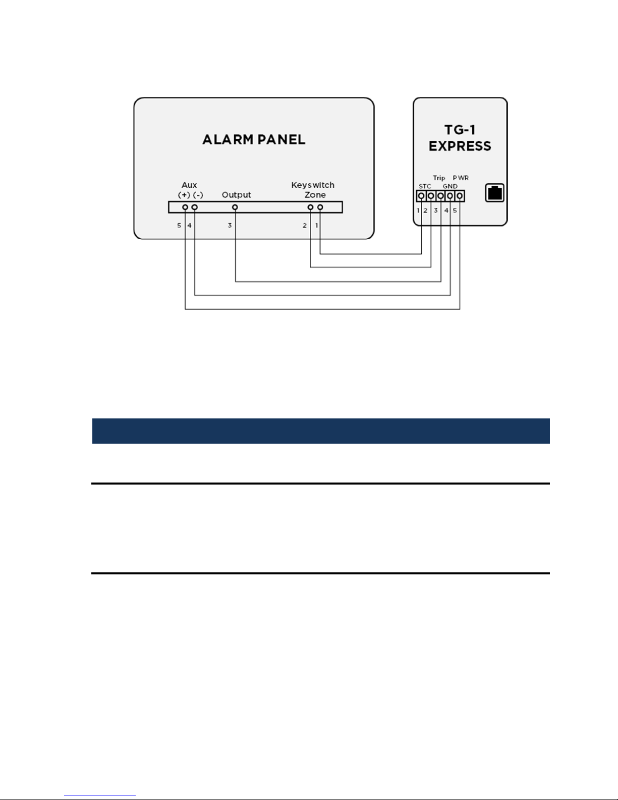
Telguard Interactive service can work in conjunction with any single-partition security
system provided that the alarm panel and Telguard are wired properly (see
illustration) and that the panel can be programmed with the following:
Alarm reporting format must programmed to Contact ID.
A programmable output must be configured to immediately switch to
ground when the system is armed and return to open state when disarmed.
An available zone must be programmed as a Momentary Keyswitch, so that
a temporary short will cause the panel to switch states (from Armed to
Disarmed and vice versa).
Opening and Closing reports must be enabled to report at all times.
Telguard Interactive will repurpose the STC and Trip Input connections. Although it is
highly recommended to use SLIC for most of the required wiring, Telguard
Interactive can be wired in one of two ways:
Telguard Interactive Wiring (using SLIC)
56046902 10 © 2014 Telular Corporation
Telguard Interactive Wiring (using terminal block)
Note: UL has not evaluated the Telguard Interactive feature. This
feature cannot be used in UL Listed Installations.
Specifications
UL Listings
UL Household Burglary (UL 1023)
UL Household Fire (UL 985)
Power Consumption
6.2Vdc, 80mA(idle), 300mA (transmitting)
12Vdc, 45mA(idle), 150mA (transmitting)
17Vdc, 38mA(idle), 124mA (transmitting)

56046902 11 © 2014 Telular Corporation
LED Indicator Guide
LED Symbol Color Showing Indication
LED #1
Activation Green
Solid On
Unit is activated
Off
Unit not activated
Flashing
Unit is disabled / Activation failed
LED #2
STC
(System Trouble
Condition)
Red
Off
ALL OK
1 Flash
STC
–
Low Power Failure
2, 3 Flashes
N/A
4 Flashes
STC
–
No Service
5 Flashes
STC
–
Radio Failure
6 Flashes
STC
–
Dial Tone Failure
7 Flashes
STC
–
Panel Presence Failure
LED #3
Mode Yellow
Flashing
C
ommunicating with alarm panel
Off
Idle state
LED #4
Acknowledgement Red
Flashing
When flashing with LED #1
,
unit has failed
activation.
Off
TG
-
1 Express
CDMA
initialized
On
TG
-
1 Express
CDMA
is waiting for response
from Telular Communications Center
LED #5
Radio Green
Off
Idle, provisioned by CDMA network
Fast Flash
(½ sec) CDMA network provisioning in progress
Slow Flash
(2 sec)
If repeating indicates CDMA provisioning is
required, otherwise indicates radio
receiving a message.
Long Flash
(3-6 sec) Radio sending message
Solid On
TG
-
1 Express
CDMA
initializing
LED #7
Trip Input Green
Solid On
Trip input activated
Off
Trip input not active or restored
LED #8
Power Red Solid On Power connected to unit

56046902 12 © 2014 Telular Corporation
Troubleshooting Guide
Telguard Event LED Indication Relay
Output
Radio
Message Action
STC
Telguard
System
Trouble
Conditions
LPF STC LED flashes
1 time.Optional None
Check input voltage
of power supplied
from the panel.
NSC STC LED flashes
4 times.Optional None
The Telguard will
continue to validate
signal strength, and
remove NSC when
signal returns.
RFC
STC LED flashes
5 times.Optional None Wait for RFC restoral.
DTF STC LED flashes
6 times.Yes Yes
Internal 30V supply
circuit failure. Return
unit for repair on
RMA.
PPF
STC LED flashes
7 times.No Yes Wait for PPF restoral.
Not Activated Activation LED
#1 off Yes None
Telguard will not
function until unit is
activated.
Activation Failed
LED #1
and
#4
flashing No None
Press RSSI
button
twice to clear fault.
Cellular network
Provisioning failed
LED #5 flashing
slowly No None
Press and hold RSSI
button for 5 seconds
to restart provisioning
Telguard Remote
Query activated by
Customer Service.
Radio LED #5
flashes during
transmit
None
Yes
(Status
data)
Telguard will send
Status data to
Telguard customer
service for review
Telguard Activation
and Configuration
Upload
Radio LED #5
flashes during
transmit
None Setup data
Telguard sends setup
configuration to the
TCC and switches to
READY state.
Disable TX
–
Communication Center
Activated.
Radio
LED #5
flashes when
transmitting
Yes
Yes
(Status
data)
TX capability is
disabled until further
notice.
Other manuals for TG-1 Express CDMA
5
Table of contents
Other Telguard Cell Phone manuals

Telguard
Telguard TG-SCI Plus User manual

Telguard
Telguard TG-1 Express CDMA User manual

Telguard
Telguard TG-4 User manual

Telguard
Telguard TG-7 Series User manual

Telguard
Telguard Dual Path Series Troubleshooting guide

Telguard
Telguard TG-1 Express CDMA User manual

Telguard
Telguard TG-1 Express CDMA User manual

Telguard
Telguard TG-7 Series Troubleshooting guide

Telguard
Telguard TG-1 Express CDMA User manual

Telguard
Telguard TG-4 User manual


