Telguard VIRALERT 3 User manual
USER GUIDE
INTEGRATED HUMAN
BODY TEMPERATURE
SCREENING SYSTEM
SAFE |EASY |ACCURATE
FROM TELGUARD AND AMETEK LAND
THE LATEST TECHNOLOGY – AVAILABLE AT
LEADING SECURITY INDUSTRY DISTRIBUTORS
IN THE U.S. AND CANADA

USER GUIDE
INTEGRATED HUMAN BODY TEMPERATURE SCREENING SYSTEM
VIRALERT 3
Health and Safety Information
Read all of the instructions in this booklet - including all the WARNINGS and CAUTIONS
- before using this product. If there is any instruction which you do not understand, DO
NOT USE THE PRODUCT.
Safety Signs
WARNING
Indicates a potentially hazardous situation which, if not avoided, could result in death or
personal injury.
CAUTION
Indicates a potentially hazardous situation which, if not avoided, could result in minor or
moderate injury to the user or users, or result in damage to the product or to property.
NOTE
Indicates a potentially hazardous situation which, if not avoided, could result in damage or loss of data.
Signs and Symbols used on equipment and Documentation
Caution, risk of electric shock.
Caution, attention to possibility of risk of damage to the product, process or surroundings. Refer
to instruction manual.
Caution, hot surface.
Protective Conductor Terminal.
Observe precautions for handling electrostatic discharge sensitive devices.
Equipment Operation
Use of this instrument in a manner not specied by AMETEK Land may be hazardous. Read and
understand the user documentation supplied before installing and operating the equipment.
The safety of any system incorporating this equipment is the responsibility of the assembler.
Protective Clothing, Face and Eye Protection
It is possible that this equipment is to be installed on, or near to, machinery or equipment operating at
high temperatures and high pressures. Suitable protective clothing, along with face and eye protection
must be worn. Refer to the health and safety guidelines for the machinery/equipment before installing
this product. If in doubt, contact AMETEK Land.
Wear Protective Gloves Wear Protective Clothing
Wear Eye Protection Wear Ear Protection
Wear Safety Boots Wear Face Protection
Electrical Power Supply
Before working on the electrical connections, all of the electrical power lines to the equipment must
be isolated. All the electrical cables and signal cables must be connected exactly as indicated in these
operating instructions. If in doubt, contact AMETEK Land.
IMPORTANT INFORMATION - PLEASE READ
Equipment Operation
Use of this instrument in a manner not specified by Telguard/AMETEK Land may be hazardous. Read and understand the
user documentation supplied before installing and operating the equipment. The safety of any system incorporating this
equipment is the responsibility of the installer.
Protective Clothing, Face and Eye Protection
It is possible that this equipment is to be installed on, or near to, machinery or equipment operating at high temperatures
and high pressures. Suitable protective clothing, along with face and eye protection must be worn. Refer to the health and
safety guidelines for the machinery/equipment before installing this product. If in doubt, contact Telguard/AMETEK Land.
Electrical Power Supply
Before working on the electrical connections, all of the electrical power lines to the equipment must be isolated. All the
electrical cables and signal cables must be connected exactly as indicated in these operating instructions. If in doubt,
contact Telguard/AMETEK Land.
IMPORTANT INFORMATION
PLEASE READ

USER GUIDE USER GUIDE
INTEGRATED HUMAN BODY TEMPERATURE SCREENING SYSTEM VIRALERT 3
Storage
The instrument should be stored in its packaging, in a dry sheltered area.
The maximum storage temperature is 140 °F (60 °C).
The minimum storage temperature is 32 °F (0 °C).
Refer to the Technical Specification for details of the operating temperature limits.
Unpacking
Check all packages for external signs of damage. Check the contents against the packing note.
Lifting Instructions
Where items are too heavy to be lifted manually, use suitably-rated lifting equipment. Refer to the Technical Specification
for weights. All lifting should be carried out in accordance with local and national regulations.
Return of Damaged Goods
IMPORTANT If any item has been damaged in transit, this should be reported to the carrier and to the supplier immediately.
Damage caused in transit is the responsibility of the carrier not the supplier. DO NOT RETURN a damaged instrument to the
sender as the carrier will not then consider a claim. Save the packing with the damaged article for inspection by the carrier.
Return of Goods for Repair
If you need to return goods for repair please contact our Customer Service Department for details of the correct returns
procedure.
Any item returned to Telguard should be adequately packaged to prevent damage during transit.
You must include a written report of the problem together with your own name and contact information, address, telephone
number, email address etc.
Design and Manufacturing Standards
The Quality Management System of Land Instruments International is approved to BS EN ISO 9001 for the design,
manufacture and on-site servicing of combustion, environmental monitoring and non-contact temperature measuring
instrumentation.
Registered ISO 9001 Management System approvals apply in the USA.
USA Calibration Laboratory: ANAB Accredited ISO/IEC 17025.
UK Calibration Laboratory: UKAS 0034.
National Accreditation Board for Testing and Calibration Laboratories approvals apply in India.
Operation of radio transmitters, telephones or other electrical/electronic devices in close proximity to the equipment while
the enclosure doors of the instrument or its peripherals are open, may cause interference and possible failure where the
radiated emissions exceed the EMC directive.
The protection provided by this product may be invalidated if alterations or additions are made to the structural, electrical,
mechanical, pneumatic, software or firmware components of this system. Such changes may also invalidate the standard
terms of warranty.
Copyright
This guide is provided as an aid to owners of Telguard/AMETEK Land’s products and contains information proprietary to
Telguard/AMETEK Land. This manual may not, in whole or part, be copied or reproduced without the expressed written
consent of Telguard/AMETEK Land.

USER GUIDEUSER GUIDE
INTEGRATED HUMAN BODY TEMPERATURE SCREENING SYSTEM
VIRALERT 3
Table of Contents
1 Introduction 01
1.1 About VIRALERT 3 01
1.2 What’s in the box? 01
1.3 Optional Accessories 02
2 System Overview 03
3 System Setup 04
3.1 Measurement Location 04
3.2 System Connections 04
4 Start the Software 06
4.1 Network Adapter Settings 06
4.2 Starting the Software 09
5 Software Settings 12
5.1 Accessing the Settings menu 12
5.2 System Settings 13
5.3 Camera Settings 20
5.4 Communication 22
5.5 Changing the Password 24
6 Specifications 25
6.1 System Specifications 25
6.2 Dimensional information 26
Disclaimer 27

USER GUIDE USER GUIDE
INTEGRATED HUMAN BODY TEMPERATURE SCREENING SYSTEM VIRALERT 3
USER GUIDE
This User Guide gives you information on how to install and set up the
VIRALERT 3 Integrated Human Body Temperature Screening System.
1.1 About VIRALERT 3
VIRALERT 3 screens people for elevated temperatures that could indicate fever.
The system is intended for use at the entrance to business premises, hospitals,
airports, schools, sporting and social gathering venues, etc.
A high-resolution camera with facial detection software identifies the part of the
image containing the subject’s face. VIRALERT 3 uses an infrared thermal imager
to determine the highest temperature in the subject’s face.
VIRALERT 3 is a screening tool. It has not been cleared or approved by the FDA
or any other regulatory agency. It should not be relied on solely or primarily to
diagnose or exclude a diagnosis of COVID-19 or any other disease.
1.2 What’s in the box?
VIRALERT 3 Integrated Human Body
Temperature Screening System
Part Number 814289
Pre-mounted on a bracket with tripod
connection
Camera to Laptop/PC power and
signal cable
With Ethernet and USB connections to
the Laptop/PC
Power cable for the Blackbody
Reference Source
International power adapters included
1 INTRODUCTION
01
USER GUIDE
INTEGRATED HUMAN BODY TEMPERATURE SCREENING SYSTEM
VIRALERT 3
1.3 Optional Accessories
Surface-Wall Mount
Part Number 814266
An adjustable mounting bracket that can be
screwed to a wall, ceiling or any other flat surface -
Connecting hardware included
Clamp-Desk Mount
Part Number 814267
A mounting bracket with a clamp to connect to a
desk or a table
Tripod
Part Number 814268
A tripod for installation on a flat surface
02

USER GUIDE USER GUIDE
INTEGRATED HUMAN BODY TEMPERATURE SCREENING SYSTEM VIRALERT 3
Fig. 2-1 VIRALERT 3 Typical System Overview
VIRALERT 3 Camera and
Blackbody Reference Source
Laptop/PC running
VIRALERT 3 Software
(requires Windows 10)
Measurement
Subject
Camera Cable
Clamp Mount
Bracket
Power Cable
2 SYSTEM OVERVIEW
2 SYSTEM OVERVIEW
3ft/1m
03
USER GUIDE
INTEGRATED HUMAN BODY TEMPERATURE SCREENING SYSTEM
VIRALERT 3
04
3 SYSTEM SETUP
3.1 Measurement Location
1) Choose a location near the entrance of the area you want to protect.
2) There must be space to install the Camera and Blackbody Reference Source
so that the Measurement Subject can face the Camera from a distance
of 3 ft/1m.
3) Avoid locations where there are possible heat sources e.g. electrical
equipment, radiators, etc. in the field of view of the camera.
4) Also avoid locations where the camera may pick up reflections from
windows, mirrors, etc.
5) VIRALERT 3 is designed to scan one person at a time. The measurement
location should not be a high-trac area where people other than the
subject will be in the field of view.
6)
During the temperature measurement process, the Subject will need to stand
still in front of the camera for approximately 2 seconds. Make sure there is
adequate provision for social distancing in your chosen measurement location.
7) The camera must have a clear, unobstructed view of the Subject’s face,
ideally with the camera at a height around eye level. If necessary, use one of
the mounting accessories available from Telguard (see Section 1.3).
8) The Blackbody Reference Source requires a power supply. You will also need
to provide power to the Laptop/PC running the VIRALERT 3 software.
9) Once the system is installed and operating, use cable ties to secure the
cables to suitable structures. This minimizes the risk of the cables becoming
dislodged and reduces the risk of tripping over the cables.
10) Posters which explain the screening process and provide instructions for your
sta and visitors on how to use the system are available for download from:
www.Telguard.com/viralert3
3.2 System Connections
NOTE: If you have purchased a mounting accessory i.e. Surface Mount Bracket, Clamp
Mount Bracket, or Tripod from Telguard, then each accessory will come supplied with
its own installation instructions
.
Camera Connection
Connect the cylindrical connector on the
power and signal cable to the Camera.
3 SYSTEM SETUP

USER GUIDE USER GUIDE
INTEGRATED HUMAN BODY TEMPERATURE SCREENING SYSTEM VIRALERT 3
05
Laptop/PC Connections
Connect the Laptop/PC to the AC power
supply.
Connect the two connectors on the other
end of the power and signal cable to the
Laptop/PC.
The power (USB) connector on the cable
looks like this.
Connect it to a USB socket on the laptop
which looks like this.
The Network signal connector on the
cable looks like this.
Connect it to a Network socket on the
laptop which looks like this.
Blackbody Reference Source Connection
Connect the smaller connector of the
source power cable to the USB port on the
Blackbody Reference Source.
Use the supplied AC adapter to connect
the cable to the AC outlet.
System connections are now complete

USER GUIDE
INTEGRATED HUMAN BODY TEMPERATURE SCREENING SYSTEM
VIRALERT 3
06
4.1 Network Adapter Settings
The correct Network Adapter Settings must be specified so that your PC can
communicate with the VIRALERT 3 Camera.
1) In the bottom left corner of your PC screen, there is a ‘Windows’ icon
Click on the icon so that it turns blue
The Windows Start menu is displayed.
2) In this text box, type in Ethernet Settings.
The Ethernet Settings screen will be similar to the screen shown in
Fig. 4-1 below.
Fig. 4-1 Typical Ethernet settings screen
4 START THE SOFTWARE
USER GUIDE USER GUIDE
INTEGRATED HUMAN BODY TEMPERATURE SCREENING SYSTEM VIRALERT 3
07
3) Click on the Change adapter options link. (See Fig. 4-2)
Fig. 4-2 Status screen
The Network Connections screen is displayed. See Fig. 4-3 below.
4) Move your mouse cursor over the icon for your Network (Ethernet in the
example below).
5) Right-click with the mouse, and select the Properties option.
Fig. 4-3 Network Connections screen
USER GUIDE
INTEGRATED HUMAN BODY TEMPERATURE SCREENING SYSTEM
VIRALERT 3
08
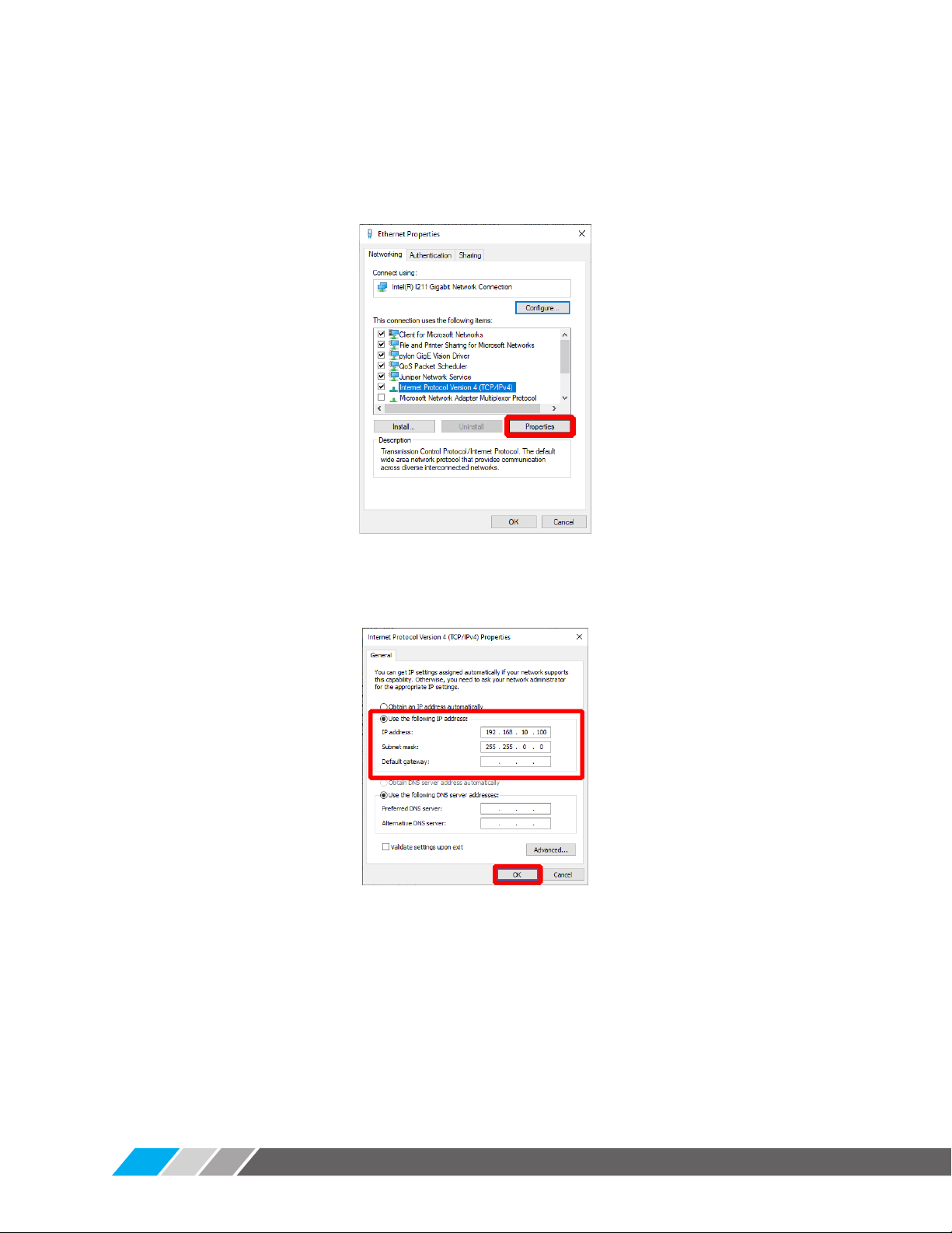
The Networking Properties screen is displayed. See Fig. 4-4.
6) Click to highlight the Internet Protocol Version 4 (TCP/IPv4) option and
click the Properties button.
Fig. 4-4 Network status search
The Internet Protocol Version 4 (TCP/IPv4) Properties screen is displayed.
See Fig. 4-5 below.
Fig. 4-5 Internet Protocol Version 4 (TCP/IPv4) Properties screen
7) Click the small round (radio) button next to Use the following IP address to
select this option.
8) In the text boxes, enter the following values:
• IP address: 192.168.10.100
• Subnet mask: 255.255.0.0
9) Click on OK to save these settings.
10) Close the Networking Properties and Network Connections screens.
The Network Adapter Settings are now complete.
USER GUIDE USER GUIDE
INTEGRATED HUMAN BODY TEMPERATURE SCREENING SYSTEM VIRALERT 3
4.2 Starting the Software
Using your own Laptop/PC, download & install the software from the Telguard website.
VIRALERT 3 software is available for download from www.Telguard.com/viralert3.
NOTE:Your computer may automatically be restarted duringthe installation
process. To avoid losing anything important, save your workand close any
open applications prior to the installation.
The minimum specifications for a computer running VIRALERT 3 are:
• i3 processor or equivalent
• 4 GB RAM
• 1 x RJ45 port and 1 x USB-A port
• 64 GB Hard disk
• Windows 10*
* If your Laptop/PC is running Windows 10 in S mode, then VIRALERT 3 will not run on this machine.
S mode runs only applications from the Microsoft Store, and requires Microsoft Edge for Internet
browsing. To run VIRALERT 3 on your machine, it should be switched to standard Windows 10 mode.
Simple instructions for this are available from support.microsoft.com
1) On the Laptop/PC, click on the VIRALERT 3 icon
The software will start automatically in Measurement mode.
2) Wait for the LED on the front panel of the Blackbody Reference Source to
turn green.
WARNING: The warm-up rate of the Blackbody Reference Source is 23 °F/ 13 °C
per minute. Therefore, from an ambient temperature of 77 °F / 25 °C it will
take approximately 1 minute for the source to reach the factory default value
of 100.4 °F / 38 °C. From an ambient temperature of 32 °F / 0 °C, it will take
approximately 3 minutes to reach the default temperature value.
3) Position a subject in front of the camera. The subject must have:
• No glasses
• No hat or hood
• No mask
• No hair covering the forehead
Posters which explain the screening process and provide instructions for your
sta and visitors on how to use the system are available for download from:
www.Telguard.com/viralert3
The software will automatically detect the presence of the subject and
calculate their body temperature.
NOTE: The default setting in the bottom left corner of the screen will be
in Celsius. This can be changed to Fahrenheit if desired by following the
instructions in Section 5.2.1 on Page 13-14.
During the measurement process, the screen background will turn yellow.
09

USER GUIDE
INTEGRATED HUMAN BODY TEMPERATURE SCREENING SYSTEM
VIRALERT 3
10
4) Follow the instructions displayed on the software screen.
Subjects with a normal body temperature are indicated by a green screen, as
shown in Fig. 4-6.
Fig. 4-6 VIRALERT 3 Software Normal Body Temperature display
Subjects with a high body temperature are indicated by a red screen, as
shown in Fig. 4-7.
Fig. 4-7 VIRALERT 3 Software Elevated Body Temperature display
Reference
Area
Measurement
Area
Blackbody
Reference
Source
Measurement
Area
Reference
Area
Blackbody
Reference
Source

USER GUIDE USER GUIDE
INTEGRATED HUMAN BODY TEMPERATURE SCREENING SYSTEM VIRALERT 3
CAUTION (REFER TO FIG 4-6 AND FIG 4-7):The VIRALERT 3 system is
supplied with the Blackbody Reference Source installed so that it is visible
in the right hand portion of the images from the camera and thermal imager.
In the thermal image, the Blackbody Reference Source must be visible
within the gray Reference Area band on the right. It must not encroach into
the Measurement Area.
If your Blackbody Reference Source moves out of position, you will need to
adjust its mounting so that it is aligned correctly.
5) Access to the Settings menu, in which you can adjust the temperature alarm
value and units of measurement, is password protected.
The default (factory-set) password is 0000.
WARNING: The threshold for an elevated body temperature alarm is a
critical parameter for use of VIRALERT 3.
You should consult a medical advisor for assistance in determining the
appropriate alarm point. The factory default value is 100.4 °F (38 °C).
For more information on the Settings menu and other features of the
software, refer to the Section 5 of this User Guide.
11

USER GUIDE
INTEGRATED HUMAN BODY TEMPERATURE SCREENING SYSTEM
VIRALERT 3
NOTE: Before changing any settings in your VIRALERT 3 system, make sure that you
read and understand the information given in this section of the User Guide.
5.1 Accessing the Settings menu
1) To access the Settings, first unlock the settings menu by clicking on the
padlock and entering your password.
The default (factory-set) password is 0000. Once unlocked, the system will
remain unlocked for 5 minutes or until you press the padlock button again.
2) Click on the link in the top left corner of the screen. See Fig. 5-1.
Fig. 5-1 VIRALERT 3 Settings Menu location
If the menu is not visible, this is due to the software being in Full Screen Mode.
2) To exit Full Screen mode, click on this button
in the top right hand corner of the screen.
The Settings menu option will now be displayed.
The menus will remain unlocked for 5 minutes or
until you press the padlock button again.
You can change the password via an option in the
Settings menu (See Section 5.5).
The options available in the Settings menu are
described in the following pages.
12
5 SOFTWARE SETTINGS
USER GUIDE USER GUIDE
INTEGRATED HUMAN BODY TEMPERATURE SCREENING SYSTEM VIRALERT 3
5.2 System Settings
To access the System Settings screen, select the System option from the
Settings menu.
The System Settings screen contains four ‘Tabs’. These are:
• General
• Alarm
• Workflow
• Logging
5.2.1 General (System Settings)
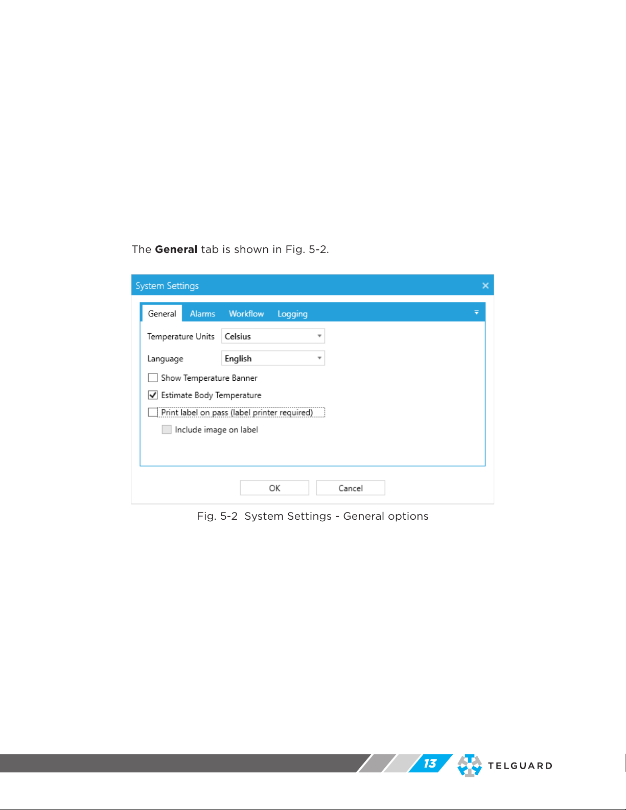
The General tab is shown in Fig. 5-2.
Fig. 5-2 System Settings - General options
13

USER GUIDE
INTEGRATED HUMAN BODY TEMPERATURE SCREENING SYSTEM
VIRALERT 3
The options available in the General tab are explained in the table below. The
default (factory-set) vales are shown in bold text.
Option Description
Temperature Units Select the required temperature units from either:
• Celsius
• Fahrenheit
Language VIRALERT 3 screens can be displayed in the following
languages. Select from:
• English
• French
• German
• Italian
• Spanish
• Chinese (simplified)
• Japanese
• Korean
• Portuguese
• Russian
Show Temperature Banner Use this checkbox to choose whether or not the
measured temperature is displayed at the top of the
VIRALERT 3 software screen.
The default is OFF.
Estimate Body Temperature Use this checkbox to choose whether or not the system
estimates a person’s body temperature based upon the
measured skin temperature.
The default is ON.
Print label on pass
(label printer required)
To use this option, you will need a BrotherQL-700
Label Printer. See Label Printing (below).
This option allows you to print a label for each
person who is screened by VIRALERT 3 and whose
temperature is below the alarm level. The label can be
attached to the person as an aid to confirming that he
or she has been screened by the VIRALERT 3. The label
shows the date and time of the measurement.
Include image on label In addition to the date and time, you can select this
option to add the visual image taken at the time of
measurement to each person’s label.
Click OK to close this window and save any changes. Click Cancel to close it
without saving your changes.
5.2.1.1 Label Printing
Supported Label Printer: Brother QL-700
VIRALERT 3, when used in conjunction with a BrotherQL-700 Label Printer, allows
you to print a label for each person who is screened by VIRALERT 3 and whose
temperature is below the alarm level.
1) To set up the printer, follow the Quick Start Guide supplied with the Brother
QL-700 label printer.
2) Download and install the required printer driver from the Brother web site.
14

USER GUIDE USER GUIDE
INTEGRATED HUMAN BODY TEMPERATURE SCREENING SYSTEM VIRALERT 3
Once installed, the printer will by default turn itself o after 60 minutes of
inactivity. To change this:
3) Type Printers and Scanners into the Windows search bar and open the
Printers and Scanners settings window.
4) Select the Brother QL-700 and click on the Manage button.
5) Click on the Printer Properties link.
The Brother QL-700 Properties window is displayed, as shown in Fig. 5-3.
Fig. 5-3 Typical Brother QL-700 Properties window
6) Go to the Device Settings tab, select Utility… and then click on the
Properties button.
The Brother QL-700 Utility window is displayed, as shown in Fig. 5-4.
Fig. 5-4 Typical Brother QL-700 Utility window
7) In the Auto power-o time setting area change the Time field to 0and click
Apply.
8) Exit all the printer properties screens.
Your label printer is now configured to work with VIRALERT 3. You may need
to restart VIRALERT 3 for these settings to take eect.
15

USER GUIDE
INTEGRATED HUMAN BODY TEMPERATURE SCREENING SYSTEM
VIRALERT 3
Fig. 5-5 System Settings - Alarms
WARNING: The threshold for an elevated body temperature alarm is a
critical parameter for use of VIRALERT 3.
You should consult a medical advisor for assistance in determining the
appropriate alarm point. The factory default value is 100.4 °F (38 °C).
The options available in the Alarms tab are explained in the table below.
Option Description
Alarm Temperature Use this text input to enter the temperature at which you
want the system to indicate an alarm.
The default value is 100.4 °F or 38 °C.
Temperature Trend This section of the screen displays a graphical
representation of ten most recent temperature readings,
plotted against the time of the reading. You can use this
graph to help you select an Alarm Temperature just above
the average for your particular application.
16
5.2.2 Alarms
The Alarms tab is shown in Fig. 5-5.
Table of contents
Popular Measuring Instrument manuals by other brands

Avantes
Avantes 785nm Operation manual

ECO Sensors
ECO Sensors OG-3 user manual

Orbisphere
Orbisphere 3600 series Operator's manual

EDT directION
EDT directION QP481 Quick user guide

iLine microsystems
iLine microsystems microINR link Instructions for use

Spectra Precision
Spectra Precision FOCUS 2 Series user guide


Granville-Phillips
Granville-Phillips Mini-Convectron 275 Series Installation, operation and service instructions

Gas Clip
Gas Clip MGC Pump user manual

Digatron
Digatron DT- 51K instructions

Greenlee
Greenlee FG01 G-Series Smart Pull instruction manual

Pessl
Pessl iMETOS RadioNode user manual

Dräger
Dräger X-am 5600 Instructions for use