Trotec T610 User manual

T610
OPERATING MANUAL
MATERIAL MOISTURE
MEASURING DEVICE
EN
TRT-BA-T610-TC-001-EN

1Operating manual – Material moisture measuring device T610 EN
Symbols
Danger!
Warns of a hazard which can lead to personal injury.
Caution!
Warns of a hazard which can lead to damage to prop-
erty.
The current version of the operating manual can be found at:
www.trotec.de
Legal notice
This release replaces all previous versions. No part of this
publication may be reproduced without written permission from
TROTEC®. The same applies for electronically processing,
duplicating or spreading the publication. Subject to technical
changes. All rights reserved. Trademarks are used without
guarantee that they may be used freely and primarily following
the spelling of the manufacturer. Product names are registered.
Changes to construction in the interests of constant improve-
ments to the product, as well as changes to the shape and colour
are reserved.
The scope of delivery may vary from product images. This docu-
ment was created with all due care. TROTEC® accepts no liability
whatsoever for possible mistakes or omissions.
The only party responsible for determining measured results to be
valid, drawing conclusions and deriving actions is the user!
TROTEC® accepts no claims of warranty for the correctness of
the determined measured values or measured results. Further,
TROTEC® accepts no liability whatsoever for possible mistakes or
damage which have been caused by utilising the determined
measured results. © TROTEC®
Warranty
The warranty is for 12 months. Damages caused by incorrect use
by untrained people or start-up by unauthorised people are
excluded from the warranty.
The device complies with the fundamental health and safety
requirements of the applicable EU regulations and was tested at
the factory for perfect functionality multiple times. However, if
faults in the functionality occur and cannot be remedied with the
measures in the chapter Errors and faults, please get in touch
with your dealer or distributor. When making a warranty claim,
supply the device number (see the rear of the device). The invoice
acts as warranty certificate. When manufacturer's instructions or
legal regulations have not been followed, or after unauthorised
changes to the device are made, the manufacturer is not respon-
sible for the resulting damages. Changes to the device or unau-
thorised replacement of individual parts can drastically impact
the electrical safety of this product and leads to the forfeit of the
warranty. Liability does not extend to damages to people or prop-
erty caused by the device being used other than as described in
the instructions in this operating manual. Subject to changes to
technical design and model changes as part of constant develop-
ment and product improvement without prior notice.
No liability is accepted for damages resulting from improper use.
In such cases, entitlements to a warranty are then also forfeited.
Table of contents
Notes regarding the operating manual .................................... 1
Information about the device................................................... 2
Technical data ........................................................................ 3
Safety ..................................................................................... 3
Transport and storage............................................................. 4
Operation................................................................................ 4
Measuring principle ................................................................ 8
PC software ............................................................................ 9
Errors and faults ..................................................................... 10
Maintenance........................................................................... 10
Disposal.................................................................................. 11
Declaration of conformity ........................................................ 11
Notes regarding the operating manual

EN Operating manual – Material moisture measuring device T610 2
Description of the device
The material moisture measuring device T610 measures the
moisture level of building material up to a depth of 30 cm by
means of microwaves.
The measurement method belongs to the dielectric measurement
methods.
A minimum, maximum and average function is available for the
direct analysis of the measured data. Besides, the currently
measured value can be recorded via the hold function.
The device can be operated via a capacitive touchscreen control
panel.
When not in use, an automatic switch-off saves the battery.
You can connect the device to a computer by using the USB cable
included in the scope of delivery. Then you can extract and ana-
lyse your measured results with the optional MultiMeasure Studio
software.
Device depiction
Cross control
Display
Information about the device
No. Operating element
1 Display
2 Cross control
3 Battery compartment with battery cover
4 On/Off key
5 USB interface
6 Measuring head
1
2
6
3
4
5
No. Operating element
7 Up key
8 Right/back key
9 Down key
10 OK button
11 Left/menu key
No. Display element
12 Configuration mode display
13 Measuring mode
14 Measurement value display top
15 Measurement value display bottom
16 Configuration mode options
7
8
11
10
9
TH
HOLD
%WT
g/m
3
g/kg
Pabs[hPa]
SENS MAT TEMP Alarm
Alt.[ft] CAL12
gr/lb dp °C °F % rH
CM m/s ppm °F °C
IR
MAX
DP
MIN AVG
CFG
ACT
15
16
12
13
14

3Operating manual – Material moisture measuring device T610 EN
Scope of delivery
The scope of delivery includes:
• 1 x Material moisture measuring device T610
• 4 x Alkaline LR6 AA, 1.5 V batteries
• 1 x USB cable
• 1 x Display protection film
• 1 x Getting started guide
• 1 x Factory test certificate
Carefully read the operating manual before using the device
and keep it within reach!
• Do not use the device in atmospheres containing oil, sulphur,
chlorine or salt.
• Never use the device for measurements at live parts.
• Ensure that all connection cables are protected from damag-
es (e.g. from kinks or crushing).
• Protect the device from permanent direct sunlight.
• Observe the storage and operating conditions (see chapter
Technical data).
Intended use
Only use the material moisture measuring device T610 for the
moisture measurement of building materials.
Here, read and observe the technical data.
To use the device for its intended use, only connect and use
accessories and spare parts which have been approved by
TROTEC®.
Improper use
Do not use the device in potentially explosive atmospheres, or for
measurements in liquids. TROTEC® accepts no liability for dam-
ages resulting from improper use. In such a case, entitlements to
a warranty are forfeited. Any unauthorised modifications, altera-
tions or structural changes to the device are forbidden.
Personnel qualifications
People who use this device must:
• have read and understood the operating manual, especially
the Safety chapter.
For maintenance or repair work which requires the housing
to be opened, contact TROTEC® customer service. Devices
which have been opened unlawfully are void of any warranty
and warranty claims.
Technical data
Parameter Value
Model T610
Dimensions (L x W x H) 191 x 63 x 35 mm
Weight incl. batteries approx. 420 g
Measuring range 0 to 200 digits
Operating range
Operating temperature 0 °C to +50 °C
Relative humidity < 90 % or < 20 g/m3 (non-condensing)
Storage
Relative humidity < 95 % (non-condensing)
Ambient temperature -20 °C to +60 °C
Energy
Battery 4 x Alkaline LR6 AA, 1.5 V batteries
comparable NiMH rechargeable batteries
(>2500 mAh)
Current consumption, active approx. 110 mA
Current consumption, passive approx. 40 μA
Battery life at least 24 h
Safety

EN Operating manual – Material moisture measuring device T610 4
Residual risks
Danger!
Do not leave the packaging lying around. Children may
use it as a dangerous toy.
Danger!
The device is not a toy and does not belong in the hands
of children.
Danger!
Dangers can occur at the device when it is used by
untrained people in an unprofessional or improper way.
Observe the personnel qualifications.
Caution!
To prevent damages to the device, do not expose it to
extreme temperatures, extreme humidity or moisture.
Transport
Use a suitable bag to transport the device safely.
Storage
When the device is not being used, observe the following storage
conditions:
• dry,
• protected from dust and direct sunlight,
• with a plastic cover to protect it from invasive dust, if neces-
sary.
• The storage temperature is the same as the range given in
the chapter Technical data.
• When storing the device for a long time, remove the batteries.
Accessories
Optionally, the following accessories are available for transport
and storage:
• TROTEC® Holster 3
For further information please contact your TROTEC® customer
service.
Inserting the batteries
• Insert the supplied batteries before first use.
Caution!
Make certain that the surface of the device is dry and the
device is switched off.
1. Open the cover of the battery compartment (3).
2. Insert the batteries in the compartment as indicated in the
figure.
3. Close the cover of the battery compartment (3).
– The device can now be switched on.
Transport and storage
Operation

5Operating manual – Material moisture measuring device T610 EN
Switch-on and measurements
Notes:
Note that moving from a cold area to a warm area can lead to con-
densation forming on the device's circuit board. This physical and
unavoidable effect can falsify the measurement. In this case, the
display shows either no measured values or they are incorrect.
Wait a few minutes until the device has become adjusted to the
changed conditions before carrying out a measurement.
Please observe the information regarding the measurement prin-
ciple.
The cross control is very sensitive. Therefore, avoid dirt on the
control panel, because it could be misinterpreted by the device as
keystroke.
Before use make sure that the touchscreen control panel is
dirt-free.
If required clean the touchscreen control panel according to
chapter Cleaning the device on page 10.
1. Hold the device pointing into clear space.
– The device should point away from the body and not at or
near material surfaces. When failing to observe the above
instructions, the following calibration will be corrupt.
2. Press the On/Off key (4) until a beep is emitted.
3. The device performs a short self-test.
– The device name and firmware version is shown on the dis-
play.
– The battery charge is indicated on the display.
– The device carries out an automatic calibration. During
calibration the display indicates the lettering CAL. These
flashing characters are accompanied by brief acoustic sig-
nals.
– An extended acoustic signal indicates that the calibration
has been completed.
– The device is ready for operation.
4. Select the desired measuring mode.
5. Place the measuring head (6) vertically on the surface of the
material to be measured. Hold the measuring head still dur-
ing the entire measuring process.
– The measured value will be displayed.
Carrying out a comparative measurement
1. Look for a preferably dry spot at the component.
2. Perform a measurement as previously described.
– The thus determined measured value will be the reference
value for dry.
3. Look for a preferably damp or wet spot at the component, if
any.
4. Perform a measurement as previously described.
– With regard to the present conditions, the thus determined
measured value will be the reference value for damp/wet.
5. Carry out further measurements at the component.
Higher measured values usually signify a higher moisture content
in the near-surface area of the material to be measured.
Carrying out a grid measurement
Particularly for larger areas, it is always recommended to perform
measurements in form of a preferably close-meshed grid, for it is
only this way that changes in the moisture content of the material
can relatively confidently be detected and occasional outliers
minimized.
1. Look for a preferably dry spot at the component.
2. Carry out at least five individual measurements within a radi-
us of approx. 20 cm.
3. Calculate the average value of the individual measurement
results.
– The average will be the reference value.
4. Carry out further grid measurements at the component.
– Higher measured values most likely signify the moisture
penetration of the measured material.
Key lock
1. Briefly press the On/Off key (4) during operation.
– The device emits a short beep.
– The following message appears on the display: LoC on.
– Key lock is activated.
2. Press the On/Off key (4) again.
– The device emits a short beep.
– The following message appears on the display: LoC off.
– Key lock is no longer activated.

EN Operating manual – Material moisture measuring device T610 6
Configuration mode
1. Press the Left/menu key (11) for approx. 2 seconds.
– The device emits a short beep.
– The CFG symbol (12) is displayed in the upper right corner.
– The available options for configuration mode (15) are dis-
played.
2. Use the cross control (2) to select the desired option.
3. Confirm the selection by pressing the OK button (10).
– The selected symbol will be illuminated.
Setting the alarm
Here you can determine the limit value for the alarm function.
Upon exceeding this value, the device emits an acoustic signal
and the indication ALARM (16) flashes. The alarm function draws
on the current digit measured value. The limit value can be deter-
mined within a range of 0.1 to 200.
1. Select ALARM (16) whilst in configuration mode.
2. Press the OK button (10) to confirm.
– The upper measurement value display (14) flashes.
3. Press the Up (7) or Down (9) key to activate or deactivate the
alarm.
– On or Off will be indicated in the upper measurement value
display (14).
4. Press the Right/back key (8).
– Depending on the selection, the alarm is either activated or
deactivated.
– The lower measurement value display (15) flashes.
5. Press the keys Left/menu (11) or Right/back (8) to select a
digit.
– The selected digit flashes.
6. Press the Up (7) or Down (9) key to change the value of the
selected digit.
7. Repeat the steps 5. and 6. until the value is set as desired.
8. Press the OK button (10) for approx. 2 seconds.
– The alarm is set.
– The device switches to measuring mode.
– With activated alarm function the indication ALARM (16)
continues to be displayed.
Adjusting the display illumination
The display illumination can be adjusted within a range of 20 to
100 %. Another available setting is AL.on (always on). AL.on fea-
tures a brightness of 100% and deactivates the automatic
switch-off function.
1. Select the lamp (16) whilst in configuration mode.
2. Press the OK button (10) to confirm.
3. Select the desired value by use of the Up (7) or Down (9) key.
4. Press the OK button (10) for approx. 2 seconds.
– The set value will be adopted.
– The device switches to measuring mode.
Configuration mode Description
ALARM Setting the threshold value for the alarm
Lamp Adjusting the display illumination
CAL Setting the offset value
TH
HOLD
%WT
g/m
3
g/kg
Pabs[hPa]
SENS MAT TEMP Alarm
Alt.[ft] CAL12
gr/lb dp °C °F % rH
CM m/s ppm °F °C
IR
MAX
DP
MIN AVG
CFG
ACT
12
16

7Operating manual – Material moisture measuring device T610 EN
Setting the offset value
By use of CAL a single-point calibration can be carried out for the
selected sensor indications. All sensors are already factory-cali-
brated and have a corresponding characteristic calibration curve.
By stating a calibration value (offset) a global shift of the calibra-
tion curve, which has an effect on the entire measuring range, is
performed for the single-point calibration! The offset value to be
entered is that value by which the calibration curve will be shifted.
Example:
The displayed value is always 5 too high => change the offset
value for this measurement channel to -5.
The offset value's default setting is 0.0.
Changing this value brings about an automatic reset of the meas-
ured values.
1. Select CAL (16) whilst in configuration mode.
2. Press the OK button (10).
3. Press the Up (7) or Down (9) key to activate or deactivate the
offset.
–On or Off will be indicated in the upper measurement value
display (14).
4. Press the Right/back key (8).
– Depending on the selection, the offset is either activated or
deactivated.
– The lower measurement value display (15) flashes.
5. Press the keys Left/menu (11) or Right/back (8) to select a
digit.
– The selected digit flashes.
6. Press the Up (7) or Down (9) key to change the value of the
selected digit.
7. Repeat the steps 5. and 6. until the value is set as desired.
8. Press the OK button (10) for approx. 2 seconds.
– The offset is set.
– The device switches to measuring mode.
– With set offset value the indication CAL (16) continues to be
displayed.
Measuring mode
1. Press the keys Right/back (8) or Left/menu (11) until the de-
sired measuring mode is displayed.
– The selected measuring mode (13) will be indicated on the
display (1).
– The current measured value is displayed in the lower
measurement value display (15).
– The values of the measuring modes AVG, MIN, MAX and
HOLD are displayed in the upper measurement value
display (14).
The device comes with the following measuring modes:
Holding the measured value
1. Set the measuring mode to HOLD.
– The current measured value will be held and displayed.
– The device will hold this value until the measured values
are set back or the device is switched off.
Resetting the measured values
1. Press the OK button (10) for approx. 2 seconds.
– All previously stored measured values of the measuring
modes AVG, MIN, MAX and HOLD will be set back.
– All measured values are then determined anew based on
the measurement proceeding in the background.
Measured value storage
Please note that measured values cannot be saved on the device
itself. In order to save measured values, the device has to be con-
nected to a PC via a USB cable using the MultiMeasure Studio
software.
1. Briefly press the OK button (10).
– The displayed measured value will be saved in the soft-
ware.
Further information can be gathered from the help text of the
MultiMeasure Studio software.
Measuring
mode Description
ACT Measured value in real time
AVG Average value of measurements since switch-on
MIN Minimum measured value
MAX Maximum measured value
HOLD Measured value will be held
TH
HOLD
%WT
g/m
3
g/kg gr/lb dp °C °F % rH
CM m/s ppm °F °C
IR
MAX
DP
MIN AVG
CFG
ACT
15
13
14

EN Operating manual – Material moisture measuring device T610 8
USB interface
The device can be connected to a PC via the USB interface (5).
See chapter PC software on page 9.
Switch-off
1. Press and hold the On/Off key (4) for approx. 3 seconds until
a beep is emitted.
– The device will be switched off.
The measurement method applied here utilizing microwaves
belongs to the dielectric moisture measurement methods.
• The measuring head generates an electromagnetic wave,
which spreads throughout the material and is reflected.
• Not only the near-surface volume elements of the measured
material contribute to the reflection of this wave, but also
those located at a lower level. The weighting of the share in
how the individual volume elements contribute drops with in-
creasing depth. This means that underlying moisture zones
have a proportionally lesser influence on the display value
than near-surface moisture penetration.
• With increasing frequencies the influence of ohmic drops
(ionic conductivities, e.g. salinization of the brickwork) de-
clines distinctly. From roughly 1 GHz these drops are almost
negligible as opposed to dielectric losses. The microwave
method is thus almost independent of the salinity degree.
Dielectric moisture measurement methods are based on the die-
lectric properties of water.
• The water molecule aligns itself in a preferential direction
within an externally applied field; it is polarizable. If an alter-
nating electromagnetic field is applied, the molecules begin
to rotate with the frequency of the field (orientational polari-
zation). This effect is described macroscopically by the phys-
ical variable dielectric constant (DK).
• For water the dielectric effect is so pronounced, that the DK
of water amounts to about 80. The DK of most solids, con-
struction materials among them, is much smaller; it is in the
range between 2 and 10, chiefly between 3 and 6. Hence
measured is the difference between the DK of water and the
DK of the building materials. Due to the great difference be-
tween these values, even small amounts of water can easily
be detected.
• With increasing frequencies it is much harder for the water
molecule to follow an externally applied alternating electro-
magnetic field owing to material-inherent bonding forces. In
a way, there is friction within the material or in other words
dielectric loss. These losses can be measured by means of
specific microwave arrangements.
Notes regarding the measurement principle
• The microwave sensor of the device at hand contains an an-
tenna arrangement enabling non-destructive penetration
depths of up to approx. 30 cm. It is suited to determine the
moisture in the volume of the measured material.
• The measurement is effected according to a reflection prin-
ciple, i.e. measured is the humidity-dependent share of the
wave, which is reflected by the material to be measured.
• The maximum penetration depth is substantially reduced
when the material to be measured or the component is
soaked in the near-surface area.
• Depending on the material and moisture level the field ad-
vances 20 to 30 cm into the good to be measured. Therefore,
the materials whose moisture is to be measured have to have
at least this thickness.
• If the material to be measured is of lesser thickness, shares
of the electromagnetic wave emitted by the sensor are re-
flected at the material's rear side, hence interfering with the
moisture-dependent reflections at the measuring head an-
tenna. Depending on the material and moisture level this ef-
fect can in part lead to substantial distortions of the
measured value.
Measuring principle
20 - 30 cm
> 20...30 cm
20 to 30 cm

9Operating manual – Material moisture measuring device T610 EN
• In order to minimize measurement errors caused by varying
material thicknesses or inhomogeneities, it is recommended
to perform a preferably close-meshed grid measurement
covering the entire area to be examined.
• The sensor's microwave field exhibits a distinct lateral ex-
pansion. A minimum distance to the side limits of the meas-
ured material must be observed, for otherwise the measured
value might be falsified. In simplified terms the measuring
volume can be seen as a cylinder with a radius of 10 to 15
cm. Therefore, the minimum distance for delimiting the ma-
terial is stated as 10 cm.
• A moisture measurement with less distance to the side edge
of the material can result in a distortion of the measured val-
ue.
• For a significant and exact measurement with the microwave
sensor it must be ensured that the observed measuring vol-
ume is sufficiently dimensioned.
• The measured values are to be interpreted as relative values,
for the microwave method only enables a differentiation be-
tween dry and wet building materials.
• The main area of use consists in comparative measurements
at the same construction material or similar components. De-
pending on the display value, humid zones can be deter-
mined and narrowed down.
• Measuring according to the microwave method is further
suited for the examination of water damage and for leak de-
tection.
• If the test material contains metal (e.g. pipes, lines, reinforce-
ments, plaster base), the measured value skyrockets. Thanks
to the depth effect (penetration), the device is also suitable for
localizing metal objects and detecting reinforcements.
• Owing to the correlation between the material's bulk density
and the dielectric constant of building materials described
above, there can be different display values with different
material densities and multi-layered wall or floor construc-
tions. Cluster measurements are recommended to avoid the
misinterpretation of the measured values. For this, at least
five individual depth measurements are carried out within a
radius of 20 cm and from these individual results an average
value is to be calculated. This value then constitutes the ref-
erence value for other cluster measuring spots.
• For a more precise analysis of homogenous materials (brick-
work thicker than 30 cm) a cluster measurement is advisa-
ble. Generally, three measurements within a radius of 15 cm
are a sufficient basis for evaluation.
Use the MultiMeasure Studio Standard PC software (free standard
version) or MultiMeasure Studio Professional (paid professional
version, dongle required) to carry out a detailed analysis and vis-
ualisation of your measured results. You can only use all config-
uration, visualisation and functional options of the device when
using this PC software and a TROTEC® USB dongle (professional).
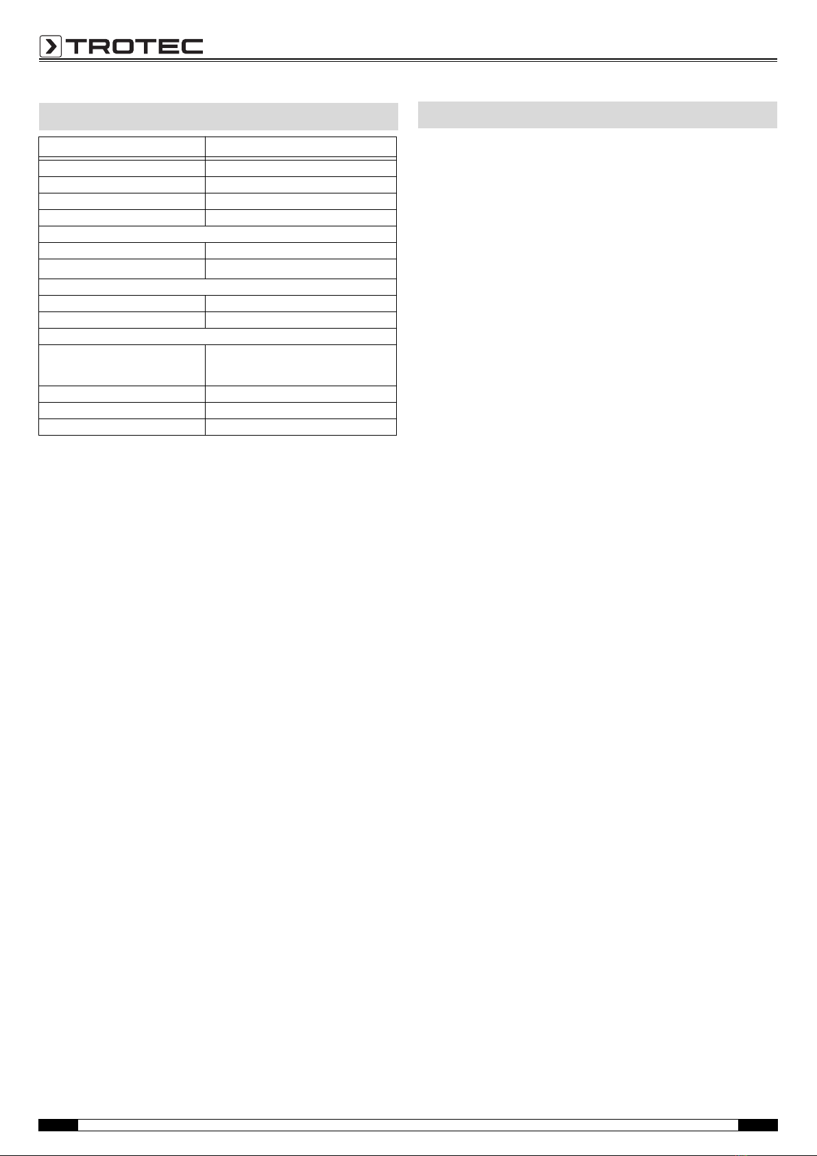
Installation requirements
Ensure that the following minimum requirements for installing the
MultiMeasure Studio Standard or MultiMeasure Studio Profes-
sional PC software are fulfilled:
• Supported operating systems (32 or 64 bit version):
– Windows XP from service pack 3
– Windows Vista
– Windows 7
– Windows 8
• Software requirements:
– Microsoft Excel (to display stored Excel files)
– Microsoft .NET Framework 3.5 SP1 (is otherwise automat-
ically installed during the software installation)
• Hardware requirements:
– Processor speed: min. 1.0 GHz
– USB connection
– Internet connection
– 512 MB RAM, minimum
– 1 GB hard disk space, minimum
– Optional: TROTEC® USB dongle (Professional) for using the
professional version of the PC software
radius:
10 to 15 cm
PC software

EN Operating manual – Material moisture measuring device T610 10
Installing the PC software
1. Download the current PC software from the Internet. To do
so, visit the website www.trotec.de. First click on Service,
followed by Downloads and then Software. Select the
MultiMeasure Studio Standard software from the list. If you
want to use the optionally available professional version of
the PC software "MultiMeasure Studio Professional"
(dongle), then get in touch with your TROTEC® customer
service.
2. Double-click on the downloaded file to start the installation.
3. Follow the instructions of the installation wizard.
Starting the PC software
1. Connect the device to your PC via the USB connection cable
provided in the scope of delivery.
Note:
Step 2 only needs to be performed, when using the Professional
software functions.
If you only use the Standard software functions, please proceed
to step 3.
2. In order to enable the Professional functions, connect the
TROTEC® USB dongle to a free USB port on your PC.
– The TROTEC® USB dongle (Professional) is automatically
detected by the operating system.
– If you only connect the TROTEC® USB dongle (Professional)
to your PC after starting the PC software, click the
Parameters menu item in the PC software. Afterwards,
click the USB symbol (dongle check) to read the connected
TROTEC® USB dongle (Professional).
3. Switch on the device (see chapter Switch-on and measure-
ments on page 5).
4. Start the MultiMeasure Studio software.
Information regarding the use of the MultiMeasure Studio soft-
ware is provided in the help text of the software.
The accurate functionality of the device was tested during pro-
duction a number of times. However, if functionality faults do
occur, then check the device according to the following list.
The device does not switch on:
• Check the charging status of the batteries. Change the bat-
teries when the message Batt lo is displayed upon switch-on.
• Check that the batteries are properly positioned. Check the
polarity is correct.
• Never carry out an electrical check yourself; instead, contact
your TROTEC® customer service.
For maintenance or repair work which requires the
housing to be opened, contact TROTEC® customer
service. Devices which have been opened unlaw-
fully are void of any warranty and warranty claims.
Cleaning the device
1. Use a soft, lint-free cloth for cleaning.
2. Dampen the cloth with clean water. Do not use sprays, sol-
vents, alcohol-based or abrasive cleaners to dampen the
cloth.
3. Clear dirt from the housing, the connections and the colour
display.
Battery change
Change the batteries when the message Batt lo is displayed upon
switch-on or the device can no longer be switched on. See Insert-
ing the batteries on page 4.
Errors and faults
Maintenance

11 Operating manual – Material moisture measuring device T610 EN
In the European Union, electronic equipment must not
be treated as domestic waste, but must be disposed of
professionally in accordance with Directive
2002/96/EC of the European Parliament and Council of
27th January 2003 concerning old electrical and electronic
equipment. After the end of its use, please dispose of this device
in a manner appropriate to the relevant legal requirements.
In the European Union, batteries must not be treated as domestic
waste, but must be disposed of professionally in accordance with
Directive 2006/66/EC of the European Parliament and Council of
6th September 2006 concerning batteries and accumulators.
Please dispose of batteries in a manner appropriate to the rele-
vant legal requirements.
in accordance with the EC Low Voltage Directive 2006/95/EC and
the EC Directive 2004/108/EC about electromagnetic compatibil-
ity.
Herewith, we declare that the T610 material moisture measuring
device was developed, constructed and produced in compliance
with the named EC directives.
The marking is found on the rear of the device.
Manufacturer:
Trotec GmbH & Co. KG
Grebbener Straße 7
D-52525 Heinsberg
Phone: +49 2452 962-400
Fax: +49 2452 962-200
E-mail: info@trotec.de
Heinsberg, 31/03/2014
Managing Director: Detlef von der Lieck
Disposal Declaration of conformity

TROTEC GmbH & Co. KG
Grebbener Str. 7
52525 Heinsberg
Deutschland
+49 2452 962-0
+49 2452 962-200
info@trotec.com
www.trotec.com
Table of contents
Other Trotec Measuring Instrument manuals

Trotec
Trotec VSC3008 User manual

Trotec
Trotec SL300 User manual

Trotec
Trotec TC100 User manual

Trotec
Trotec bz30 User manual

Trotec
Trotec T500 User manual

Trotec
Trotec BZ26 User manual

Trotec
Trotec MultiMeasure Basic BA15 User manual

Trotec
Trotec BE40 User manual

Trotec
Trotec BG30 User manual

Trotec
Trotec IC085LV User manual
Popular Measuring Instrument manuals by other brands

Hanna Instruments
Hanna Instruments HI 96741C instruction manual

TPI
TPI SP555 manual

Raycom
Raycom WPM user manual

Anritsu
Anritsu VectorStar ME7828A Series quick start guide

PCB Piezotronics
PCB Piezotronics IMI SENSORS ICP M604B11/M005BZ Installation and operating manual

Audio Precision
Audio Precision B Series installation instructions