Telic Picotrack User manual

Picotrack 4G User Manual
29.10.2020

General document information
Title EN_UserManual_Picotrack 4G
Date
29.10.2020
Author
Regina Kniegl
Contact at Telic AG
Document version
1.2

Picotrack 4G User Manual V1.2
Seite 3
Content
Picotrack 4G User Manual ........................................................................................................................... 1
Table Overview.............................................................................................................................................. 4
Figure Overview ............................................................................................................................................ 4
Introduction................................................................................................................................................... 5
Delivery content............................................................................................................................................ 6
Technical Data............................................................................................................................................... 7
Operation Setup............................................................................................................................................ 8
Opening the device................................................................................................................................... 8
Inserting the SIM Card.............................................................................................................................. 8
Closing the housing .................................................................................................................................. 9
Switching the device ON and OFF........................................................................................................... 9
Status Indicators .....................................................................................................................................11
Troubleshooting hints................................................................................................................................ 13
The device doesn’t show any sign of life..............................................................................................13
The device doesn’t log into the mobile network.................................................................................13
The device doesn’t log into the GPRS network ...................................................................................14
The device doesn’t send messages ......................................................................................................14
The device doesn’t receive GPS data....................................................................................................14
Basic Features ............................................................................................................................................. 15
Event Types..............................................................................................................................................15
Connection Establishment Procedure .................................................................................................15
Event Message Structure .......................................................................................................................16
Advanced Features ..................................................................................................................................... 17
Geofencing...............................................................................................................................................21
Roaming alternative configuration.......................................................................................................21
Device Watchdogs...................................................................................................................................22
Device-based wireless positioning .......................................................................................................22
Device Installation on Board ..................................................................................................................... 22
Safety............................................................................................................................................................ 23
General Battery handling.......................................................................................................................23
Battery storage........................................................................................................................................23
Battery Disposal ......................................................................................................................................24
General Terms and Conditions................................................................................................................. 24
Document History....................................................................................................................................... 24

Picotrack 4G User Manual V1.2
Seite 4
Table Overview
Table 1: Accessories List .............................................................................................................................. 6
Table 2: Technical Data ................................................................................................................................ 7
Table 3: Status indicators .......................................................................................................................... 12
Table 4: The device doesn’t show any sign of life...................................................................................13
Table 5: The device doesn’t log into the GSM network..........................................................................13
Table 6: The device doesn’t log into the GPRS network ........................................................................14
Table 7: The device doesn’t send messages ........................................................................................... 14
Table 8: The device doesn’t receive GPS data.........................................................................................14
Table 9: Content Description..................................................................................................................... 16
Table 10: Document History...................................................................................................................... 24
Figure Overview
Figure 1: How to open the device............................................................................................................... 8
Figure 2: How to inserting the SIM Card.................................................................................................... 9
Figure 3: Switch the device off .................................................................................................................. 10
Figure 4: Geofencing .................................................................................................................................. 21

Picotrack 4G User Manual V1.2
Seite 5
Introduction
The Picotrack is a small sized tracking device which is well suited for tracking valuable goods and
shipments. The Picotrack is suited for a wide range of asset tracking applications including the
following (this list is not exhaustive!):
Tracking of valuable goods and shipments (Product prototypes, cash transport, high value
products)
Tracking product packaging (e.g. pallets & crates…)
Mobile industrial equipment
Because of the multitude of possible application we cannot list them all. Therefore we will only
refer to installation scenarios as they occur in asset tracking applications.
Picotrack: For all applications where smallest dimensions are essential and a longer battery
lifetime is required.
Picotrack IP69K: The Picotrack is provided inside an IP69K grade casing, which is can also be
supplied with a magnet (as optional accessory) for quick installation on metallic surfaces. It is
suited for all applications where long battery lifetime is needed and the device is subjected to
harsh environmental conditions.
Picotrack 4G User Manual V1.2
Seite 6
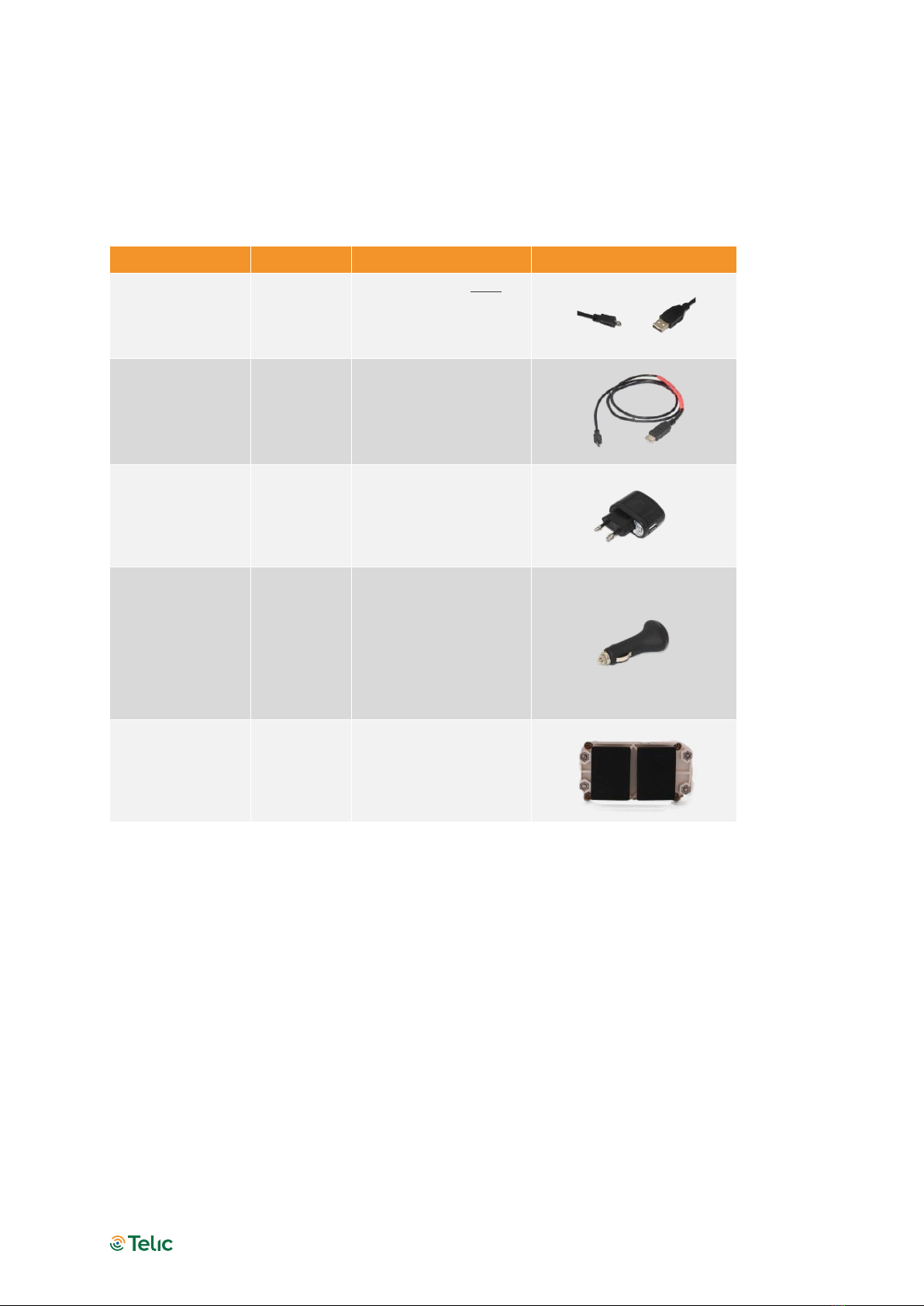
Delivery content
The standard delivery includes the Picotrack device. The delivery could include furthermore some
of the following accessories, depending on the details of your purchase order:
Accessory Name Oder code Functionality Picture
USB-A / Micro-
USB-B-Cable
17005
Use this cable only to
charge the device
(but not for
configuring it).
Cable for
Config- Tool
Picotrack
16207
Use this cable to
charge or to
configure the device
via the Telic Config-
Tool.
Picotrack power
supply w/o USB-
cable
17003
Use this power
adapter to connect
the device to a mains
supply.
Picotrack
cigarette lighter
charger w/o
USB-cable
17004 Use this adapter to
connect the device to
a cigarette lighter.
Magnet plates
for Picotrack
IP69K
17020 Used for installation
on metallic surfaces.
Table 1: Accessories List

Picotrack 4G User Manual V1.2
Seite 7
Technical Data
Components Picotrack Picotrack IP69K
Dimensions
57x38x19 mm 95x50x39 mm
Environmental Rating N/A IP69K protected
Connectors
Charging cable
Status LEDs
3 indicators for the states:
Cellular, GPS, On/Off, battery charging/full, DOTA, On/Off
button…
Cellular/GPRS module Quadband-LTE-Module with 2G fallback at 850 MHz / 900 MHz /
1800 MHz / 1900 MHz
GPS Sensitivity (Tracking) -165 dB
GPS Acquisition Time Cold ~ 34sec ; Warm ~ 33 sec ; Hot < 1 sec
GPS Tracking / Acquisition
Channels
22/66 channel
Battery 1320 mA/h
Message Logging
Capacity 2800
Cellular/GPS antennas Both integrated
Operating Temperature -20°C to +60°C
Recharging Temperature 0°C to +45°C
Supply voltage 5V USB
Certificates RoHs, CE certificated
Table 2: Technical Data
Picotrack 4G User Manual V1.2
Seite 8
Operation Setup
The operation set-up of the Picotrack device can be realised in a few quick steps.
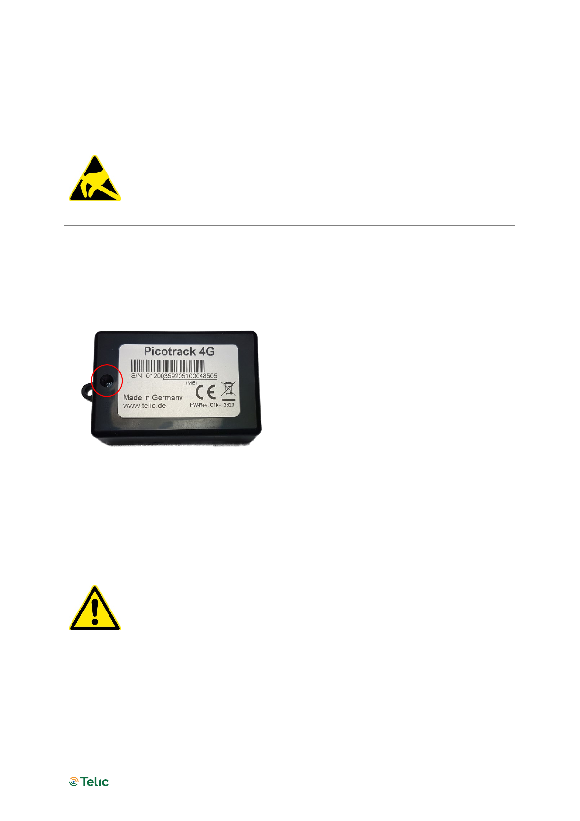
Please take proper measures for ESD protection (e.g. electrical connection of the
body to ground) to make sure you do not destroy internal electronics! Repair of
ESD damages caused by user’s negligence will not be covered by Telic’s warranty.
Electrostatic discharge (ESD) is the sudden and momentary electric current that flows
between two objects at different electrical potentials normally caused by static
electricity.
Opening the device
Open Picotrack housing by screwing off the housing (as shown in the following Figure). The SIM
card holder is under the battery and allows to slide-in and to fix a standard Mini-SIM card. Be
careful when moving the battery not to pinch the battery cable.
Figure 1: How to open the device
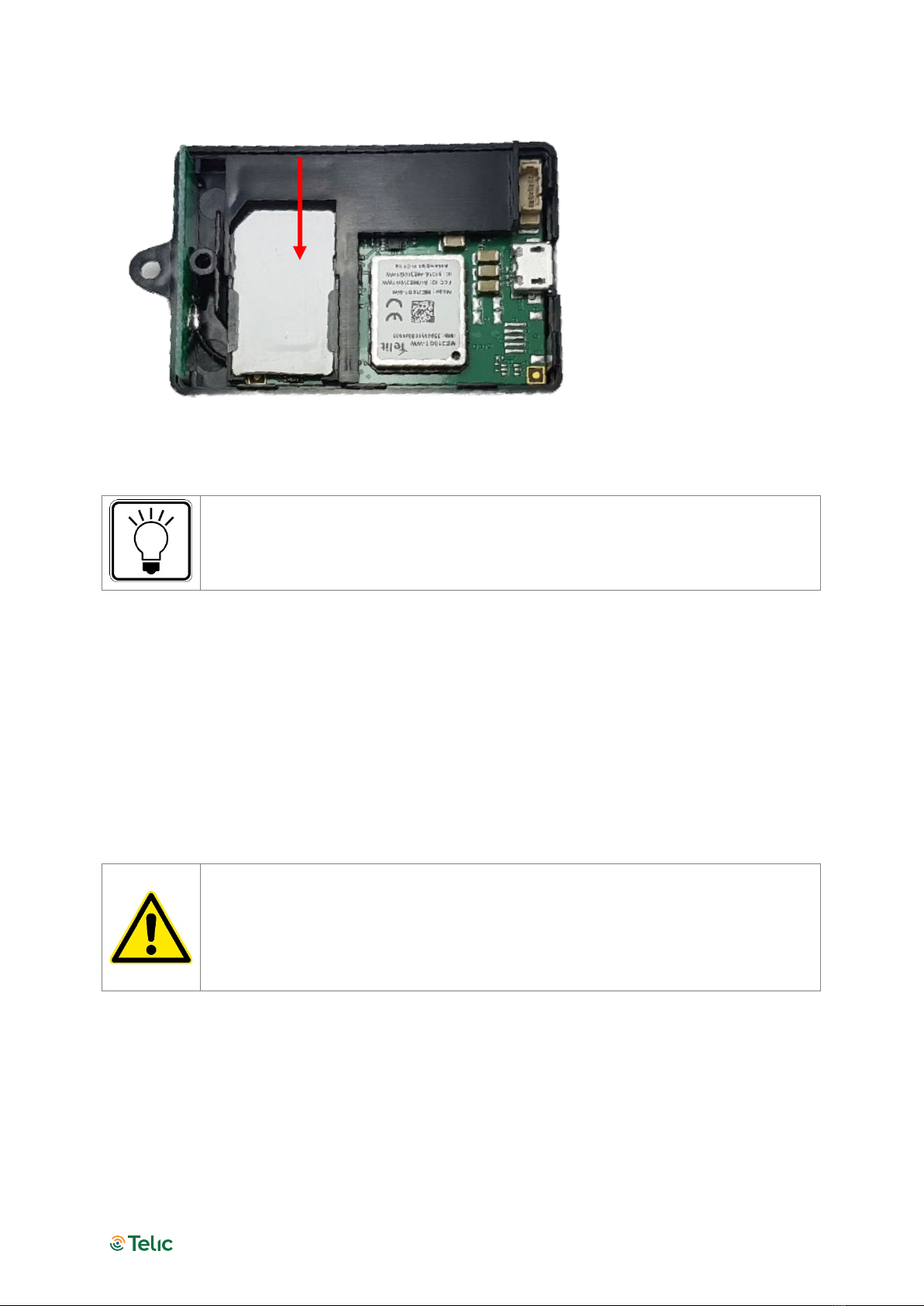
Inserting the SIM Card
A working SIM card from a suitable network provider must be correctly inserted in order to the
device operates correctly.
The messages of the Picotrack are transmitted via the mobile GSM network.
Therefor you need a standard 3 Volts or 1.8 Volts SIM card. Please give preference
to post-paid SIM cards!
Please put the device in front of you on your desk so that you can slide-in the SIM card (as shown
in the following Figure); the gold contacts of the SIM card must be facing down. The SIM card
must be pushed in the direction of the arrow, until it snaps into place.
Picotrack 4G User Manual V1.2
Seite 9
Figure 2: How to insert the SIM Card
The opposite cover of the housing, in which the GPS receiver is embedded, should
not be opened, to avoid a contamination of the receiver which may lead to a
reduction of receiving quality (should you be forced to clean the pad sometime,
please do so using pure alcohol).
Before the Picotrack logs into the mobile GSM network, it checks whether the used SIM card is
PIN free. If it is PIN free, it will start normal operation.
If the SIM card is not PIN free, it has to be assured, that the PIN is set to “0000” before it has been
inserted. The PIN can be changed e.g. with a normal mobile phone to “0000”.
To speed up the log-in into the mobile network, the SIM card should not contain any phone book
entries.
Closing the housing
Make sure that the battery is not damaged or squeezed by the holder of the
housing while closing the device, and that the battery cable is not pinched or
kinked.
Avoid any stress on the micro USB connector when it is plugged in the Picotrack. In
the worst case, the connector of the Picotrack board could be damaged. Telic’s
warranty does not cover the repair of this type of damage.
Close the device again and take care that the housing covers fit together tightly and properly.
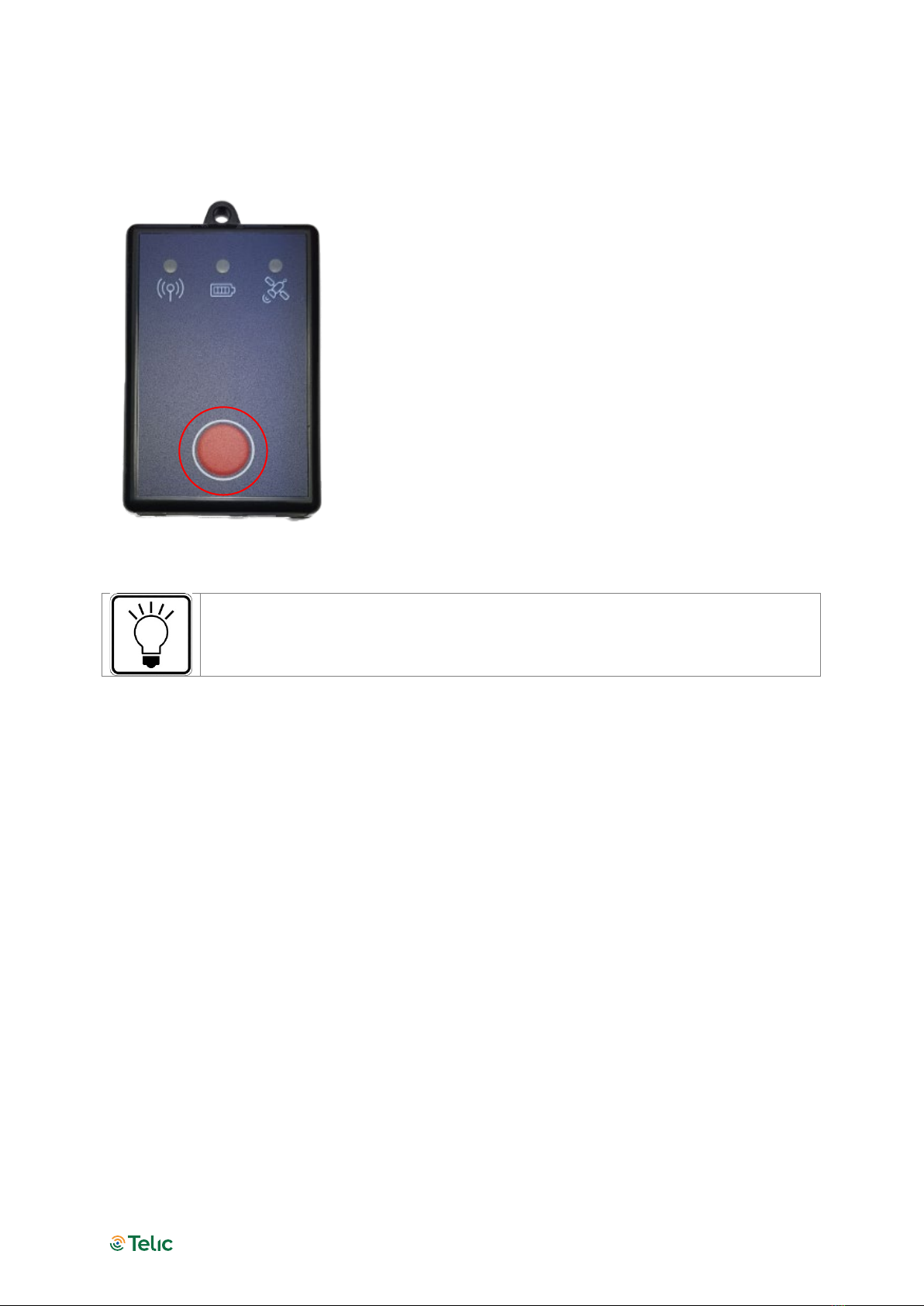
Switching the device ON and OFF
To switch the device ON: push the red button until the green LED of the left GSM-indicator
lights up.
Picotrack 4G User Manual V1.2
Seite 10
To switch the device OFF: push the red button twice in quick succession. Note that the green
LED of the left GSM indicator will continue to light-up for a while, even though the switch-off
process is on its way.
Figure 3: How to switch on and off the device
Pushing the red button will always be confirmed by the red LED in the centre
indicator, which means it will be illuminated as long as the button is being pushed.
Picotrack 4G User Manual V1.2
Seite 11
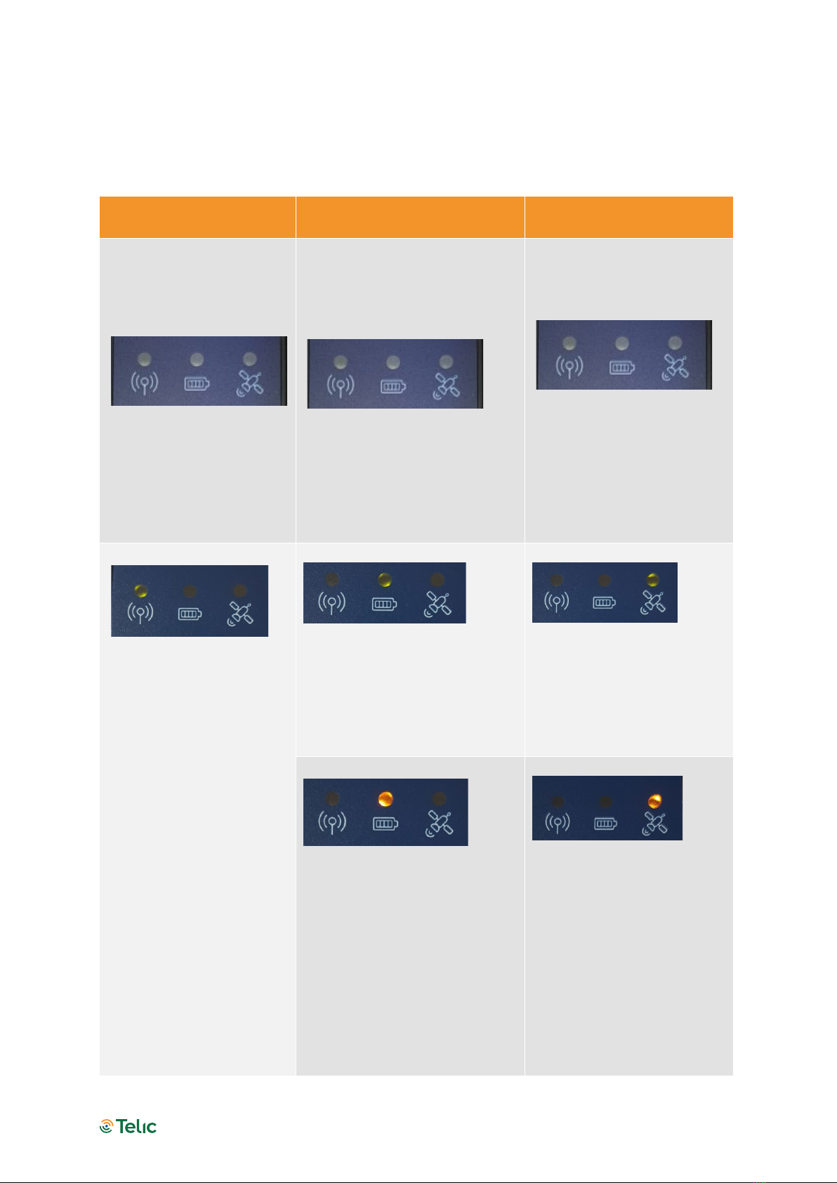
Status Indicators
Internally the device has three status indicators each indicator has 2 or 3 different colored LEDs
closed grouped together.
Left indicator: Cellular
status
Middle indicator: Power
supply status Right indicator: GPS status
The left indicator reflects
the GSM status and also,
whether the device is
switched on.
When the LED is off, the
device is switched off.
The middle indicator reflects the
status of the integrated battery
as well as of the DOTA
download.
The middle LED being off does
NOT mean that the device is
switched off. It only indicates
that the device is not connected
to external power supply.
The right indicator reflects
GPS reception as well as the
device reset status.
Off: GPS is not switched on
Permanently on: GSM is
switched on, but no GSM
network is available.
Blinking once: the device is
logged into the GSM
network.
Blinking twice: TCP/IP
connection to the server
has been established
Permanently on: GSM is
switched on, but no GSM
network is available.
Permanently on: the device has
external power supply and the
battery is fully charged.
2 times blinking: 2D- Fix (no
valid height and the position
may be imprecise
3 times blinking: 3D (GPS
data are complete
Permanently on: the battery is
currently charging.
The middle indicator works
identically if the device is in
sleep mode; just the left and the
right indicators are off.
1 time blinking: position
acquisition not possible

Picotrack 4G User Manual V1.2
Seite 12
Slow double blinking: the
SIM card is not readable
(e.g. if not correctly
inserted into the SIM
cardholder or others).
After a certain period of
time the Picotrack will
switch-off completely (as it
would be after pushing
twice the red on/off
button).
The red LED is permanently on
during the whole DOTA
(Download Over The Air)
procedure.
About 5 seconds red during
device reset.
Table 3: Status indicators

Picotrack 4G User Manual V1.2
Seite 13
Troubleshooting hints
The device doesn’t show any sign of life
Possible issue source
Trouble shooting
The battery is not
connected to the PCB.
Connect the battery to the printed circuit board (PCB).
The battery is empty. Charge or replace the battery.
The device is not
switched on.
Press once the red on/off button to turn the device on.
Table 4: The device doesn’t show any sign of life
The device doesn’t log into the mobile network
Possible issue source Trouble shooting
The device isn’t in a GSM
covered area
Please check whether there is GSM reception in this area (e.g.
using a cell phone) and move eventually to another area.
The position of the
Picotrack device is not
favourable.
Choose another place in the vehicle which might be less
shielded.
The SIM card in the
Picotrack device is new
and has not yet been
activated
Please check, whether the SIM card is already activated.
This can be done e.g. by putting the SIM card into your cell
phone and checking, whether your cell phone is able to log into
a GSM network.
The SIM card has been
locked by the provider
Please check whether the SIM card is locked.
This can be done e.g. by putting the SIM card into your cell
phone and checking, whether your cell phone is able to log into
a GSM network.
If this not the case, then please try to make a phone call. If you
are successful, the SIM card is definitely not locked.
The prepaid bonus is
exhausted
Please recharge the SIM card in the Picotrack device.
The prepaid SIM card is
no longer valid
If they aren’t recharged on a regular basis (often after 12 or 24
months).
In this case usually you have to buy a new SIM card.
The PIN code of the card
has not been deactivated
or is not set to “0000”
Please remove the SIM card from the device and check the PIN
code.
The Pin code has to be deactivated or set to “0000”
After a triple wrong entry of the PIN, unblocking the SIM card
requires the PUK.
The SIM card hasn’t been
inserted into the SIM card
holder in the correct way
Please check the correct position of the SIM card in the card
holder.
Table 5: The device doesn’t log into the GSM network

Picotrack 4G User Manual V1.2
Seite 14
The device doesn’t log into the GPRS network
Possible issue source Trouble shooting
The GPRS service is not
yet activated
Please ask your provider, whether the GPRS function is already
activated for the SIM card in use.
Table 6: The device doesn’t log into the GPRS network
The device doesn’t send messages
Possible issue source Trouble shooting
Battery of the device was
completely drained (e.g.
after several weeks of
storage)
Please recharge the device and wait for 3D GPS fix to
synchronise the internal real time clock.
Table 7: The device doesn’t send messages
The device doesn’t receive GPS data
Possible issue source Trouble shooting
The position of the device
is not favourable for the
GPS reception
Please check, whether the device has the indicators facing up
and a clear view of the sky.
The GPS receiver has no
free sight to the sky
Please be aware, that a GPS receiver operates most efficiently
when there is a clear view of the sky. Please ensure that the
device side with the LEDs has free view to the sky.
Your asset is placed in an
unsuitable location
Please consider that a GPS reception operates most efficiently
when there is a free view of the sky.
If GPS reception is not available (e.g. due to location of the asset
inside a warehouse), considering using the Device-based
Wireless Positioning feature as an alternative positioning
method (see Section 0).
Table 8: The device doesn’t receive GPS data
Further hints regarding sources of errors are indicated through the 8 LEDs of the 3 indicators,
which are easily visible from outside. You will find details of the meaning of the different colours
and blinking signs in Section 0 (“Status Indicators”).

Picotrack 4G User Manual V1.2
Seite 15
Basic Features
The device can be configured either via serial cable by using the Telic Configuration tool or
remotely via SMS and GPRS. Please contact the Telic support team to receive more details about
the configuration procedure.
Event Types
The Picotrack’s primary task is to transmit GPS positioning data as well as additional status
information via a TCP/IP connection to the tracking server. If a message can’t be transmitted, it
will be stored in the device for transmission at a later point in time. There is a storage capacity of
about 1.000 position messages. The following events will generate a positioning message which
always contains the GPS position:
Time event: the end of a time period of x seconds (x being configurable).
Distance Event: after a distance of x meters (straight line distance to the previous event) in any
direction (x being configurable) has been travelled.
Angular change Event: a direction change of a configurable minimum angle in x degrees (x
being configured) at a configurable minimum speed of y km/h (y being configurable).
Periodic Wakeup / Routine Message: even when the unit is in stand-by mode, the message is
generated either every x hours (x being configurable) or at a fixed time (configurable) during the
day
Power event: Switching on or off the device.
Connection Establishment Procedure
The GSM and GPS modules will power up after switching on the Picotrack device. After logging in
into the GSM network the Picotrack will attempt to establish a GPRS communication link. Finally,
a TCP/IP connection to the tracking server will be established to transmit the event messages.
The selection of the GSM network operator will take about 1 minute, plus the time to build up the
GPRS- and TCP/IP-connections to the tracking server. Therefore, after switching on the device, it
will take approximately 2-3 minutes until the first status message can be transmitted.
Independent of this procedure, GPS positions and status information will be generated and
stored in the internal memory for later transmission. Here follows the message structure:

Picotrack 4G User Manual V1.2
Seite 16
Event Message Structure
The first identified and valid GPS position will be taken as the reference position for the distance
interval calculations. The next distance interval event will be generated if the configured distance
has been reached. If another event (e.g. time interval event) has been generated before, the
distance interval measurement starts again at the position of this new event. That means that
any position message with an actual GPS position sets a new reference for the distance interval
calculations. This reduces the number of messages sent while still keeping the desired resolution
of the tracking application.
A position message will also be generated in the case of a direction change being greater than
the configured angle while travelling at the configured minimum speed.
Switching on and off the external Power supply (e.g. ignition on/off) also leads to an event
message. The last valid position will be transmitted when no new valid GPS position is available.
Content Description
Event/Log –Code Reason for the status message
Event/Log Timestamp Time at which the event has happened
GPS Timestamp
GPS timestamp at the moment of fetching longitude and
latitude
Longitude Degree of longitude in 100µ degrees
Latitude Degree of latitude in 100µ degrees
Fix Type 1,2 or 3, depending on the availability of satellites in view having
a sufficient signal strength:
1D Fix (no valid data)
2D Fix (no height indication)
3D Fix (position message with height indication)
Speed over ground Speed in km/h
Satellites for calculation Actual number of satellites which are used for calculation
Height Height above sea level (in m)
Mileage Mileage in km
DigIns 4 digits e.g. 0010, if charger is connected
Analog Input 1
Value of the analogue input 1, i.e. Battery voltage with a
precision of 1/10 volts
MotSens Status of the motion sensor
Table 9: Content Description

Picotrack 4G User Manual V1.2
Seite 17
Power modes
The Pickotrack can work with several power modes based upon the customer’s needs.
This allows to save the power consumption as much as possible and to extend the battery runtime.
The available power modes are listed below.
Full power mode
Microcontroller, mobile service and GNSS modules are always on.
Timer Sleep Mode
The device enters the sleep mode between the timer events (events generated every x minutes,
being x configurable). During sleep mode mobile and GNSS are turned off and microcontroller is in
low power mode. An input can be configured to wake up and stay awake until the input goes to
low again.
Motion Sleep Mode
If the motion sensor detects stationary, the device will switch off GNSS and mobile service modules,
and the micro controller is switched to low power mode. Changes from "stationary" to "moving" will
always wakeup
the system. Then it will stay awake as long as the sensor detects movement. GNSS and mobile
modules are turned on. If the device detects "stationary" for the stationary detection time period,
the device goes into the sleep mode after 60 seconds.
An input can be configured to wake up and stay awake until the input goes to low again.
Endurance Mode
Basically the Endurance Mode is similar to the Timer Sleep mode, combined with the Motion Sleep
Mode. As long as the device is moving, it behaves like in Timer Sleep mode. As soon as it falls to
stationary it wakes up, sends the stationary event (if configured) and falls back to sleep until the
next movement without generating cyclic messages. This sleep in stationary state can be
interrupted by routine or fixed reporting time events.
Basic configuration
The device can be configured via either serial interface or SMS.
In the first case you will need the Cable for Config-Tool Picotrack (Order code 16207) and a serial
terminal program (e.g. Realterm).
In the second case, you will need in the device a SIM supporting SMS (M2M SIMs typically don’t
support them).
Before you insert the SIM card and activate the device, make sure the PIN is disabled or set to 0000.
Otherwise it can happen that the PIN is entered incorrectly three times, and the SIM falls into the PUK
lock.
This would be deactivated again by a mobile phone.
When sending SMS to a device through a mobile phone, the phone number of the latter must be
visible (not hidden), otherwise the device won’t send its reply to the sender.

Picotrack 4G User Manual V1.2
Seite 18
Afterwards, you can check the flashing behaviour, Mobile LED should flash once, when the device is
logged into the mobile network, and twice when an IP connection to the server is established.
More detailed information can be found in the „Status Indicators“ chapter of this manual.
A lot of parameters can be configured in order to implement the proper use case.
Besides, the unit has to be configured in order to forward messages (events) to the proper server; in
the following paragraphs some scenarios will be illustrated as examples (all the details can be found in
the Software Protocol Specification, basic and expert type).
Tracking – typical configuration profiles
Pedestrian & Vehicle Live (1min interval)
Position messages are generated every 60 seconds when in motion, regardless of speed or
changes of driving direction.
This means that a position message is generated and transmitted every 2 km on a freeway or
highway (driving with about 120km/h).
As soon as motion is ended (detected by built-in sensor), the device will go to sleep mode. When
going back to motion (detected by the sensor), the device will automatically resume tracking.
A routine event (“I am alive”) will be sent once a day.
Then the power mode will be motion-sleep mode (5), and time interval 60 sec.
The following extra messages are generated and sent to the server (value=2in the 32 bytes
sequence detailed below):
Power Supply connected / disconnected
Ignition signal on / off
Digital Input 2 signal on / off
Digital Input 4 signal on / off
Device stopped moving (30 seconds without any sensor motion detection)
Device started moving (according motion sensitivity level 3)
Periodic Wakeup / Routine message (every 24 hours)
Configuration SMS :
0011{6digitsIMEI},,,,60,0,200000700000,50000009,00000000022222220000000022000000,,,,,,0,0,0
,0,24,,,,3,30,,,,30,6
Configuration command through serial line:
CONFIG=,,,,60,0,200000700000,50000009,00000000022222220000000022000000,,,,,,0,0,0,0,24,,,,3,
30,,,,30,6
Remark
:
the “0011{6digitsIMEI}” of the SMS becomes “CONFIG=” in the serial command; the rest
remains unchanged.

Picotrack 4G User Manual V1.2
Seite 19
Vehicle - Medium Resolution - Off by Motion
Position messages are generated either after 5 km distance or as soon as the driving direction
has been changed more than 45 degrees provided that the vehicle is exceeding 20Km/h.
Driving long distances will be covered by one position message every 5 km, driving short
distances is managed by generating position messages whenever the driving direction is
significantly changed.
As soon as the vehicle has stopped (detected by sensor) the device will go to sleep mode. When
vehicle goes back to move, the device will automatically resume tracking.
Power mode: motion-sleep mode (5)
Distance interval: 5,000 m
Course change: 45 degrees
Minimum Speed: 20 Km/h
In addition the following extra messages are generated and sent to the server:
Power On
Ignition signal on / off
Digital Input 2 signal on / off
Device stopped moving (1 minute without any sensor motion detection)
Device started moving (according motion sensitivity level 3)
Configuration SMS:
0011{6digitsIMEI),,,,0,5000,020000700000,50000009,20000200002222000000000022000000,,,,,,0,
0,0,0,24,,,,3,60,,,,45,20
Vehicle - Low Resolution Track (10min interval)
Position messages are generated in 10 minutes time intervals regardless of motion, speed or
changes of driving direction.
This profile should be used for long distance tracking applications.
Power mode: timer-sleep mode (4)
Time interval: 600 sec
Configuration SMS:
0011{6digitsIMEI},,,,600,0,200000700000,40000009,00000000000000000000000000000000,,,,,,0,0,
0,0,24,,,,3,60,
Vehicle - High Resolution Track - Off by Ignition
When the ignition is on, position messages are generated and sent either after an 1 km distance
has been travelled or as soon as the driving direction has been changed more than 30 degrees;
additionally a position message is sent every 5 minutes.
Driving long distances will be covered by one position message every km, driving short distances
is managed by generating position messages as soon as the driving direction is changed more
than 30 deg.
As soon as the Ignition signal is detected as off, the Picotrack will enter the sleep mode.
This profile should be used for all kind of tracking applications where a high accurate position
track is needed.

Picotrack 4G User Manual V1.2
Seite 20
Power mode: input sleep mode (1)
Time interval: 300 sec
Distance interval: 1,000 m
Course change: 30 degrees
In addition, the following extra messages are generated and sent to the server:
Power Supply connected / disconnected
Ignition signal on / off
Digital Input 2 signal on / off
Device stopped moving (1 minute without any sensor motion detection)
Device started moving (according motion sensitivity level 3)
at 9:00am and 08:00pm (UTC) an inventory message is sent regardless the ignition state
Configuration SMS:
0011{6digitsIMEI},,,,300,1000,220000700000,10000009,00000200022222220000000022000000,,,,,,
0,540,1200,0,24,,,,3,60,,,,30,6
Connection to the server – configuration
In case you use your own server, the SW integration of Telic’s proprietary protocol is mandatory
(otherwise received data will be meaningless).
The following configuration command sets some IP parameters in the device, allowing the same
to connect the proper server.
00b1{6 digits-IMEI}IP Address,IP Port,APN,USERNAME,PASSWORD,
(SMS command)
Or:
IPCONFIG=IP Address,IP Port,APN,USERNAME,PASSWORD,
(serial command)
APN, USERNAME and PASSWORD must be adapted according to the SIM card (Provider).
In case there is no Username (or Password), you have to digit: “”.
When you send an SMS, you must wait for an SMS reply by the device (Ack) confirming IP address,
port, and APN credentials (you can disregard the other parameters).
Example:
IP Address: 78.137.103.86 (this is in particular the IP address of telic.kentaur.cc)
IP Port: 1561
APN: internet.m2m.de Username: m2m Password: sim
{IMEI} = last 6 or 15 digits of IMEI – 353322088958773
Final SMS:
00b195877378.137.103.86,1561,internet.m2m.de,m2m,sim,
Reply by the device:
This manual suits for next models
1
Table of contents
Other Telic GPS manuals


