TELINK SEMICONDUCTOR TLSR8278DG48D User manual

Telink Dongle TLSR8278DG48D User
Manual
TELINK SEMICONDUCTOR
Keyword:
Features; Pin connection; User manual
Brief:
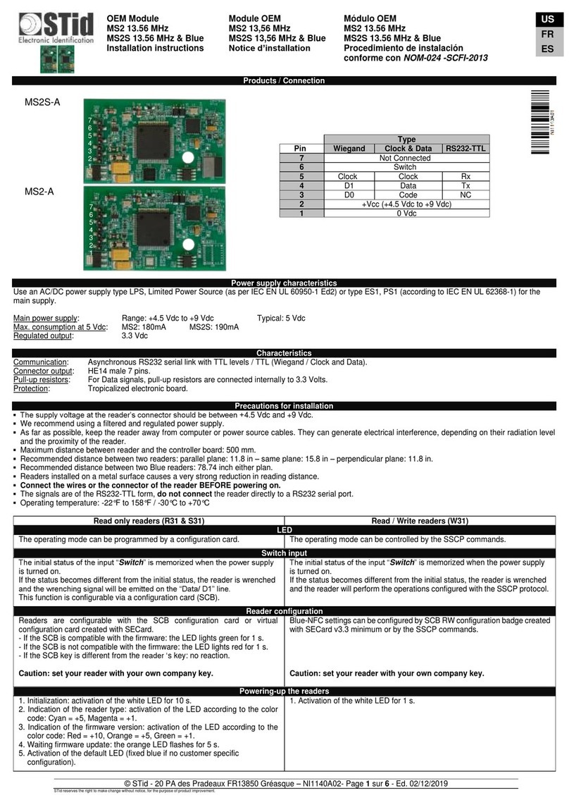
This is a user manual for Telink 8278 Dongle.

Telink Dongle TLSR8278DG48D User Manual
1
Published by
Telink Semiconductor
Bldg 3, 1500 Zuchongzhi Rd,
Zhangjiang Hi-Tech Park, Shanghai, China
© Telink Semiconductor
All Right Reserved
Legal Disclaimer
This document is provided as-is. Telink Semiconductor reserves the right to make
improvements without further notice to this document or any products herein. This
document may contain technical inaccuracies or typographical errors. Telink
Semiconductor disclaims any and all liability for any errors, inaccuracies or
incompleteness contained herein.
Copyright (c) 2019 Telink Semiconductor (Shanghai) Ltd, Co.
Information:
For further information on the technology, product and business term, please
contact Telink Semiconductor Company (www.telink-semi.com).
For sales or technical support, please send email to the address of:
telinkcnsales@telink-semi.com
telinkcnsupport@telink-semi.com

Telink Dongle TLSR8278DG48D User Manual
2
Table of contents
1Product Introduction ..............................................................................................3
1.1 General description..........................................................................................3
1.2 Key features .....................................................................................................3
2Pin Connection Guide .............................................................................................4
2.1 Supply power ...................................................................................................4
2.2 Download firmware .........................................................................................5
2.3 Test RF signal....................................................................................................6

Telink Dongle TLSR8278DG48D User Manual
3
1Product Introduction
This is a user manual for Telink Dongle TLSR8278DG48D.
1.1 General description
The TLSR8278DG48D, which is based on Telink TLSR8278F1KET48 chip,
provides a Bluetooth LE .
The TLSR8278DG48D integrates a power-balanced 32-bit
MCU, BLE , 64kB SRAM, 512kB internal Flash, 14bit ADC , 6-channel PWM, flexible
GPIO interfaces, and nearly all the peripherals needed for IoT (Internet of Things)
and HID (Human Interface Devices) application development (e.g. Bluetooth
Low Energy ).
The TLSR8278DG48D supports standards and industrial alliance specifications
including Bluetooth Low Energy (up to Bluetooth 5), BLE Mesh, 6LoWPAN,
Thread, HomeKit .
1.2 Key features
Bluetooth 5 Compliant, 1Mbps, 2Mbps, Long Range 125kbps and 500kbps
64kB on-chip SRAM with up to up to 32kB retention
A rich set of I/Os: SPI, I2C, Single wire, up to 32 GPIOs, UART with hardware flow
control and 7816 protocol support, DMIC (Digital Mic), AMIC (Analog Mic), I2S,
Stereo Audio output
6-channel PWM (Pulse Width Modulation) output
6-channel (only GPIO input), 14-bit SAR ADC with 10.5-bit ENOB
4-channel PGA, differential input
RSSI monitoring with +/-1dB resolution
Power supply: DC3.3V

Telink Dongle TLSR8278DG48D User Manual
4
2Pin Connection Guide
2.1 Supply power
The TLSR8278DG48D supports supply power via battery or other 3.3V power.
The power connection is shown below, connect the power to the 3V3 of J6, and
connect the GND to the GND of J6.
Figure 1 Connection chart to supply power

Telink Dongle TLSR8278DG48D User Manual
5
2.2 Download firmware
To download firmware into TLSR8278DG48D, first make sure the
TLSR8278DG48D is supplied with power normally. That is, connect the power to the
3V3 of J6, and connect the GND to the GND of J6.
Then connect J6(SWS) of the TLSR8278DG48D with SWM of a burning EVK.
Meanwhile, connect the miniUSB interface of the burning EVK with PC USB.
Figure 2 Connection chart to download firmware

Telink Dongle TLSR8278DG48D User Manual
2.3 Test RF signal
To test RF signal of TLSR8278DG48D, first make sure the TLSR8278DG48D is
supplied with power normally. That is, connect the power to the 3V3 of J6, and
connect the GND to the GND of J6.
Attach the semi-rigid cable welding steel to the PCBA GND. Then solder wire
core to feed point.
Figure 3 Connection chart to test RF signal
Feed point
GND
FCC statement
This device complies with Part 15 of the FCC rules. Operation is subject to the following two conditions: 1) this device may not cause harmful interference, and 2) this device must accept any
interference received, including interference that may cause undesired operation.
This equipment has been tested and found to comply with the limits for a Class B digital device, pursuant to Part 15 of the FCC rules. These limits are designed to provide reasonable
protection against harmful interference in a residential installation. This equipment generates, uses and can radiate radio frequency energy and if not installed and used in accordance with
the instructions, may cause harmful interference to radio communications. However, there is no guarantee that interference will not occur in a particular installation. If this equipment does
cause harmful interference to radio or television reception, which can be determined by turning the equipment off and on, the user is encouraged to try correct the interference by one or
more of the following measures:
- Reorient the receiving antenna.
- Increase the separation between the equipment and receiver.
- Connect the equipment into and outlet on a circuit different from that to which the receiver is connected.
- Consult the dealer or an experienced radio/TV technician for help.
Changes or modifications not expressly approved by the party responsible for compliance could void your authority to operate the equipment.
Table of contents
Popular Computer Hardware manuals by other brands
Freescale Semiconductor
Freescale Semiconductor Windows Embedded CE 6.0/Windows CE 5.0 i.MX31 PDK... quick start guide
LJ
LJ MAC III 6502 user manual

Elvaco
Elvaco CMi6110 quick start guide
Addonics Technologies
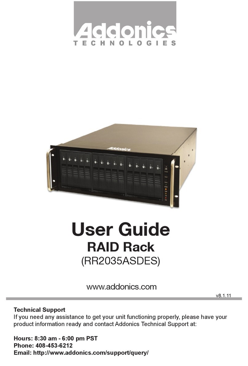
Addonics Technologies RR2035ASDES user guide

Samoa
Samoa 383 300 Parts and technical service guide

Reach
Reach Bee3 Plus user manual
