TELink 1200 User manual

TELink 1200 Rev. 4/25/01
80-001200
TELink 1200
INSTALLATION AND OPERATION MANUAL
Please leave this manual with the unit after installation
Important warranty information enclosed - see page 2.
Nel-Tech Labs, Inc.

TELink 1200 2 Rev. 4/25/01
FCC Notice
WARNING: This equipment has been tested and found to comply with the limits for a Class A digital device pursuant to
Part 15 of FCC Rules. These limits are designed to provide reasonable protection against harmful interference when this
equipment is operated in a commercial environment. This equipment generates, uses, and can radiate radio frequency
energy and, if not installed and used in accordance with the instruction manual, may cause harmful interference to radio
communications. Operation of this equipment in a residential area is likely to cause harmful interference in which case the
user will be required to correct the interference at his/her own expense.
This digital apparatus does not exceed the Class A limits for radio noise emissions from digital apparatus set out in the
Radio Interference Regulations of the Canadian Department of Communications.
Le présent appareil numérique n'émet pas de bruits radioélectriques dépassant les limites applicables aux appareils
numériques de la Class A prescrites dans le Règlement sur le brouillage radioélectrique édicté par le ministère des
Communications du Canada.
LIMITED WARRANTY
TERMS: Nel-Tech warrants to the original purchaser ("Buyer") that the Product sold is free from defects in material and
workmanship at the time of purchase. The warranty extends five (5) years from the date of original purchase and covers
parts and labor. Buyer must provide written notice to Nel-Tech within the warranty period of any defective part or
conditions. If the defect is not the result of improper use, service, maintenance or installation, and if the equipment has not
been otherwise damaged or modified after shipment, Nel-Tech or its authorized representative shall either replace or
repair the defective Product at Nel-Tech's option. No credit shall be allowed for work performed by Buyer or unauthorized
parties. Out-of-warranty repairs will be invoiced at the current Nel-Tech hourly rate plus the cost of parts, shipping and
handling. IN THE EVENT THAT THE PRODUCT SERIAL NUMBER IS MISSING OR HAS BEEN TAMPERED WITH IN
ANY WAY, THE FOREGOING WARRANTY IS VOID AND WITHOUT EFFECT AND NEL-TECH SHALL HAVE NO
LIABILITY WHATSOEVER ON ACCOUNT OF DEFECTS TO SUCH PRODUCT.
LIMITATIONS: EXCEPT AS STATED ABOVE, THERE ARE NO WARRANTIES, EXPRESS OR IMPLIED, THAT
EXTEND BEYOND THE SPECIFICATIONS FOR THE PRODUCT. NEL-TECH EXPRESSLY DISCLAIMS ANY
WARRANTY, EXPRESS OR IMPLIED, THAT EQUIPMENT SOLD HEREUNDER IS OF MERCHANTIABLE QUALITY OR
THAT IT CAN BE USED, OR IS FIT FOR ANY PARTICULAR PURPOSE. BUYER PURCHASES AND ACCEPTS
EQUIPMENT SOLELY ON THE BASIS OF THE WARRANTY HEREINABOVE EXPRESSED. UNDER NO
CIRCUMSTANCES SHALL NEL-TECH BE LIABLE BY VIRTUE OF THIS WARRANTY OR OTHERWISE FOR ANY
SPECIAL, INDIRECT, SECONDARY OR CONSEQUENTIAL DAMAGES TO ANY PERSON OR PROPERTY ARISING
OUT OF THE USE OR INABILITY TO USE THE PRODUCT.
REPAIRING OR REPLACING PRODUCT: Buyer may obtain the repair or replacement of any flawed part or equipment
covered under this warranty through Nel-Tech only. Buyer is responsible for all shipping and handling charges in
connection with the performance of this warranty. Products returned to Nel-Tech must be securely packaged to prevent
damage in transit, freight prepaid, and insured for replacement value. A return authorization number assigned by Nel-
Tech must be clearly marked on the outside of the shipping container. Proof of purchase must accompany shipment.
Items delivered to Nel-Tech without a return authorization clearly marked on the outside of the shipping container, and/or
without proof of purchase will be refused. Please contact Nel-Tech at the address and phone number below to receive a
return authorization number and to arrange for the repair or replacement of a flawed part covered by this warranty. Please
indicate the Product's serial number in all correspondence; an authorization number will not be issued in the absence of a
serial number.
Nel-Tech Labs, Inc.
101 Zachary Road
Manchester, NH 03109-5609
Tel: (603) 641-8844
This manual Copyright 1997-2001 by Nel-Tech Labs, Inc. All rights reserved. No part of it may be copied, photocopied, reproduced, translated, or
reduced to any electronic medium or machine-readable form without Nel-Tech's prior written consent.
Information contained herein is subject to change without prior notification. Nel-Tech Labs, Inc. provides this manual without warranty of any kind,
expressed or implied. This user's manual may contain technical and/or typographical errors.
Printed in the U.S.A.

TELink 1200 3 Rev. 4/25/01
TABLE OF CONTENTS
FCC Notice ........................................................................................................2
LIMITED WARRANTY ...........................................................................................2
1. System Description ...........................................................................................4
2. Installation .....................................................................................................5
Voice Line ...................................................................................................6
Dedicated Line .............................................................................................7
Fax Share ...................................................................................................8
Final Installation ............................................................................................9
3. Additional Features ...........................................................................................9
4. Troubleshooting............................................................................................. 11
TELink 1200 4 Rev. 4/25/01
1. System Description
The TELink 1200 is a telephone loadable multi-message digital announcement system that can play
up to 32 minutes of audio messages for in-store message broadcasting or telephone messaging on
hold. Using your Background Music (BGM) source, the TELink 1200 fades the BGM, plays a
message, then restores the BGM. The time between message play can be set anywhere from 0
seconds (continuous play) to 9999 seconds (approx. 2 hours and 45 minutes). Available message
configurations are 1, 2, 4, 8, or 16 separate messages.
Once installed, no further interaction from the user is required. Unlike other messaging products, the
TELink 1200 is designed to be operated remotely by the messaging provider using a specially-
equipped computer (the "PC Controller"). This feature eliminates the need for tape distribution
because all audio information and configuration settings are sent from the PC Controller to the
TELink over telephone lines.
The TELink 1200 features non-volatile FLASH memory, which means your messages are safe from
erasure due to power loss for up to 10 years. If power is lost, message playback resumes
automatically when power is restored. This feature eliminates the need for a battery backup system.
The TELink 1200 has been designed to accommodate several different installation needs. In a
standard installation, the unit is installed on a voice line, allowing normal access to the line while
automatically preventing an unintentional disruption of communications between the TELink 1200
and the PC Controller. Additionally, the unit can be installed on a dedicated line, or can share a line
with a fax machine on a non-interference basis.
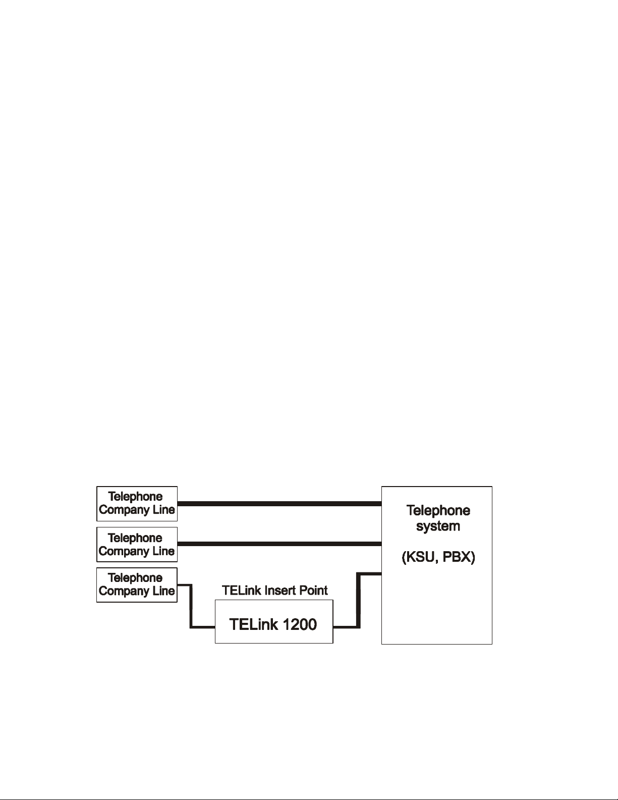
Whichever line is selected for the TELink 1200, the unit must be installed directly to the telephone
company phone line, with no other telephone equipment connected prior to the TELink. An
installation involving a KSU or PBX may look like what is illustrated below.

TELink 1200 5 Rev. 4/25/01
2. Installation
If your messaging provider included other installation instructions, those
instructions should be followed first.
There are three installation procedures available:
•Use Installation Procedure A if the installation phone line is also used as a normal voice line.
•Use Installation Procedure B if the unit is to be installed on a phone line dedicated
exclusively to the TELink.
•Use Installation Procedure C if the installation phone line is to be shared with a fax machine.
Keep in mind that whichever procedure is used, the TELink must always be connected directly to the
telephone company input, ahead of any other devices using that line.
If you have any questions or require assistance installing the TELink, please
contact your messaging provider.

TELink 1200 6 Rev. 4/25/01
INSTALLATION PROCEDURE A
(Voice Line)
1. Make sure the power switch on the back of the TELink is OFF.
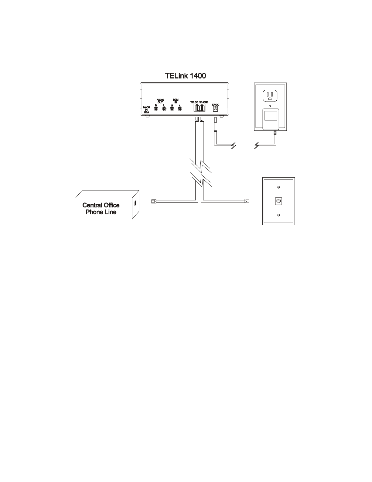
2. Connect one end of the included modular telephone cable directly to the phone company box for
the installation phone number. It is important that this cable is attached to a direct line, prior to any
other telephone equipment. The user may need to adapt one end of the modular cable to mate to
the incoming phone line.
3. Connect the other end of the modular cable to the TELCO jack on the back of the TELink.
4. Using another modular telephone cable, connect the PHONE jack on the back of the TELink to the
installation phone line's original destination (KSU, PBX, telephone, etc).
5. Set the HI/LO switch on the back of the TELink to the proper position for the sound system (LO=8
Ohm, HI=600 Ohm).
6. Connect the TELink's AUDIO OUTPUT jack to the sound system's input using the included RCA
cable. The user may need to adapt the sound system end of this cable to match the sound
system's input jack.
7. Connect your BGM source to the TELink's BGM INPUT jack. Make sure the BGM source is on,
set up properly, and providing audio output.
8. Plug the included 12VDC power supply into a 110VAC wall outlet. Connect the other end to the
12VDC jack on the back of the TELink.
9. Turn the power switch ON. Turn to page 9 for further instructions.

TELink 1200 7 Rev. 4/25/01
INSTALLATION PROCEDURE B
(Dedicated Line)
1. Make sure the power switch on the back of the TELink is OFF.
2. Connect one end of the included modular telephone cable directly to the phone company box for
the installation phone number. It is important that this cable is attached to a direct line, prior to any
other telephone equipment. The user may need to adapt one end of the modular cable to mate to
the incoming phone line.
3. Connect the other end of the modular cable to the TELCO jack on the back of the TELink.
4. Set the HI/LO switch on the back of the TELink to the proper position for the sound system (LO=8
Ohm, HI=600 Ohm).
5. Connect the TELink's AUDIO OUTPUT jack to the sound system using the included RCA cable.
The user may need to adapt the sound system end of this cable to match the sound system's input
jack.
6. Connect your BGM source to the TELink's BGM INPUT jack. Make sure the BGM source is on,
set up properly and providing audio output.
7. Plug the included 12VDC power supply into a 110VAC wall outlet. Connect the other end to the
12VDC jack on the back of the TELink.
8. Turn the power switch ON. Turn to page 9 for further instructions.
TELink 1200

TELink 1200 8 Rev. 4/25/01
INSTALLATION PROCEDURE C
(Fax Share)
1. Make sure the power switch on the back of the TELink is OFF.
2. Connect one end of the included modular telephone cable directly to the phone company box for
the installation phone number. The TELink must be connected before the fax machine. The user
may need to adapt one end of the modular cable to mate to the incoming phone line.
3. Connect the other end of the modular cable to the TELCO jack on the back of the TELink.
4. Using another modular telephone cable, connect the fax machine to the PHONE jack on the back
of the TELink.
5. Set the HI/LO switch on the back of the TELink to the proper position for the sound system (LO=8
Ohm, HI=600 Ohm).
6. Connect the TELink's AUDIO OUTPUT jack to the sound system using the included RCA cable.
The user may need to adapt the sound system end of this cable to match the sound system's input
jack.
7. Connect your BGM source to the TELink's BGM INPUT jack. Make sure the BGM source is on,
set up properly, and providing audio output.
8. Plug the included 12VDC power supply into a 110VAC wall outlet. Connect the other end to the
12VDC jack on the back of the TELink.
9. Set the fax machine to answer on two or more rings. The messaging provider must set the TELink
to answer two rings AFTER the fax machine.
10. Turn the power switch ON. Turn to page 9 for further instructions.

TELink 1200 9 Rev. 4/25/01
Final Installation
After installation is complete, a message download may be required. Check the STATUS light on the
front panel.
IF IT IS ON (STEADY): Audio messages are already loaded in memory. Download may not be
required.
IF IT IS FLASHING SLOWLY: No messages are present in memory. Contact your messaging
provider. They must call the unit and download audio.
IF IT IS FLASHING FAST: The unit is automatically calling the callback number stored in memory to
download audio from the PC Controller. This first callback to the PC Controller must be successful in
order to validate the callback number. If the first call does not result in contact with the PC
Controller, then callback validation has failed and the unit will not call again. In this case, the
STATUS light will alternate between a flash fast for one second and no flash for one second.
Contact your messaging provider. They may then call the unit and download audio.
During communications sessions between the TELink and the PC Controller, the STATUS light
flashes fast and the phone line becomes unavailable for incoming and outgoing calls (no dial tone will
be present). This is to prevent disruption of the download - the line is released after download is
complete. After a successful download the STATUS light remains on (steady).
While listening to the audio play over the sound system, adjust the volume on the BGM source, the
TELink, and/or the sound system as required to achieve the desired output level. Note: The volume
buttons on the TELink control the message volume only, not the BGM volume, which can only be
adjusted on the BGM source itself.
If you hear the BGM feed, but not messages, this is not a malfunction. The TELink is likely waiting
out the time interval between message play. This delay can be anywhere from 0 seconds (no delay
in between) to 9999 seconds (about 2 hours and 45 minutes). Check with your service provider to
find out what time interval has been set for your machine.
If there is no sound system output at all, go back and compare the connections against the
installation procedure used (A, B, or C), and check the BGM source and sound system for proper
operation. If you still have difficulty, contact your messaging provider.
STATUS Light Indication
STATUS Light Indication
On Messages present in memory, currently playing
(or in delay between messages).
Off No power to unit or an error has occurred.
Flashing Slowly No audio file in memory, phone line free.
Flashing Fast Data session with PC Controller is being
attempted or is in progress.
Alternating –
Fast Flash / No Flash
The TELink failed to validate the callback
number. Contact your messaging provider.
3. Additional Features

TELink 1200 10 Rev. 4/25/01
Your TELink 1200 has features which provide additional convenience and functionality. Note that
one or both of these features may have been disabled by your messaging provider.
CALL ON SCHEDULE allows the TELink to be programmed to call the PC Controller at a future
date and time to automatically download new audio messages. The scheduled callback can be set
to a specific time, month, day, and year.
The STATUS light flashes fast during a callback. If the unit cannot connect to the PC Controller (for
instance, if the line is busy), it will continue calling at seven minute intervals until a connection is
made, or until the preprogrammed number of retries has been exhausted.
Before Call On Schedule can operate automatically, the callback telephone number must be
validated during initial installation and whenever the callback number is changed by the messaging
provider. During validation, the TELink makes one call attempting to establish communications with
the PC Controller. If it is successful, the feature becomes operational. If validation fails (indicated
by the STATUS light alternating between 1 second fast flash/1 second no flash) contact your
messaging provider.
FAX SHARE allows the TELink to share a phone line with a fax machine, saving the expense of
having to install a separate line. In a Fax Share installation, the TELink only answers calls from the
PC Controller and does not interfere with incoming or outgoing fax transmissions because the fax
machine always answers first. The fax machine must be set to answer on two or more rings, and
the TELink must be set to answer two rings AFTER the fax machine. Example: fax machine set to
answer on second ring; TELink set to answer on fourth ring.

TELink 1200 11 Rev. 4/25/01
4. Troubleshooting
Problem / Symptom Possible Solution(s)
Message and/or BGM volume is
too low or too high.
•Adjust the volume on the TELink, the BGM
source, and/or the sound system as required.
Note: The TELink’s volume buttons adjust the
message volume only. The BGM volume can only
be adjusted on the BGM source itself.
•Possible impedance mismatch between the
sound system and the TELink. Try switching the
HI/LO switch on the back of the TELink.
•BGM source will not pass through to the sound
system unless the TELink has power and is turned
ON.
TELink does not answer when
called by the PC Controller.
•Make sure the TELink is connected directly to
the telephone company input. The TELink must be
the first device connected to where the telephone
line enters the building.
•In a fax line installation, the fax machine must
be set to answer on at least two rings, and the
TELink set to answer two rings AFTER the fax
machine.
Can’t get a dial tone on the
TELink’s phone line.
•The TELink may be communicating with the PC
Controller. The unit automatically locks it phone
line during communications to protect data integrity.
Check the STATUS led. If it is flashing fast, the
unit is in a data session.
STATUS light alternates between 1
second fast flash and 1 second no
flash
•First attempt to call the callback phone number
ahs failed.
•If the initial callback validation fails, contact your
messaging provider for further instruction.
If you require further assistance, contact your messaging provider.

TELink 1400 Rev.
04/25//01
80-000031
TELink 1400
INSTALLATION
OPERATION MANUAL
Please leave this manual with the unit
after installation
Important warranty information enclosed - see page 2.
FCC Notice

TELink 1400 Rev. 04/25/01
WARNING: This equipment has been tested and found to comply with the limitsfor a Class Adigital device pursuantto
Part 15 of FCC Rules. These limits are designed to provide reasonable protectionagainstharmfulinterference whenthis
equipment is operated in a commercial environment. This equipment generates, uses, and can radiate radio frequency
energy and, if not installed and used in accordance with the instruction manual, may cause harmful interference to radio
communications. Operation of this equipment in a residential area is likely to cause harmful interferencein which case
the user will be required to correct the interference at his/her own expense.
This digital apparatus does not exceed the Class A limits for radio noise emissions from digital apparatus set out in the
Radio Interference Regulations of the Canadian Department of Communications.
Le présent appareil numérique n'émet pas de bruits radioélectriques dépassant les limites applicables aux appareils
numériques de la Class A prescrites dans le Règlement sur le brouillage radioélectrique édicté par le ministère des
Communications du Canada.
LIMITED WARRANTY
TERMS: Nel-Tech warrants to the original purchaser ("Buyer") that the Product sold is free from defects in material and
workmanship at the time of purchase. The warrantyextends five (5) years from the date of original purchase andcovers
parts and labor. Buyer must provide written notice to Nel-Tech within the warranty period of any defective part or
conditions. If the defect is not the result of improper use, service, maintenance or installation, and if the equipment has
not been otherwise damaged or modified after shipment, Nel-Tech or its authorized representative shalleitherreplace or
repair the defective Product at Nel-Tech's option. No credit shall beallowed forworkperformed byBuyeror unauthorized
parties. Out-of-warranty repairs will be invoiced at the current Nel-Tech hourly rate plus the cost of parts, shipping and
handling. IN THE EVENT THAT THE PRODUCTSERIAL NUMBER IS MISSING OR HAS BEEN TAMPERED WITH IN
ANY WAY, THE FOREGOING WARRANTY IS VOID AND WITHOUT EFFECT AND NEL-TECH SHALL HAVE NO
LIABILITY WHATSOEVER ON ACCOUNT OF DEFECTS TO SUCH PRODUCT.
LIMITATIONS: EXCEPT AS STATED ABOVE, THERE ARE NO WARRANTIES, EXPRESS OR IMPLIED, THAT
EXTEND BEYOND THE SPECIFICATIONS FOR THE PRODUCT. NEL-TECH EXPRESSLY DISCLAIMS ANY
WARRANTY,EXPRESSORIMPLIED,THATEQUIPMENTSOLDHEREUNDER ISOF MERCHANTIABLEQUALITYOR
THAT IT CAN BE USED, OR IS FIT FOR ANY PARTICULAR PURPOSE. BUYER PURCHASES AND ACCEPTS
EQUIPMENT SOLELY ON THE BASIS OF THE WARRANTY HEREINABOVE EXPRESSED. UNDER NO
CIRCUMSTANCES SHALL NEL-TECH BE LIABLE BY VIRTUE OF THIS WARRANTY OR OTHERWISE FOR ANY
SPECIAL, INDIRECT, SECONDARY OR CONSEQUENTIAL DAMAGES TO ANY PERSON OR PROPERTY ARISING
OUT OF THE USE OR INABILITY TO USE THE PRODUCT.
REPAIRING OR REPLACING PRODUCT: Buyer may obtain the repair or replacement of any flawed part or equipment
covered under this warranty through Nel-Tech only. Buyer is responsible for all shipping and handling charges in
connection with the performance of this warranty. Products returned to Nel-Tech must be securely packaged to prevent
damage in transit, freight prepaid, and insured for replacement value. A return authorization number assigned by Nel-
Tech must be clearly marked on the outside of the shipping container. Proof of purchase must accompany shipment.
Items delivered to Nel-Tech without a return authorization clearly marked on the outside of the shipping container,and/or
without proof of purchase will be refused. Please contact Nel-Tech at the address and phone number belowtoreceivea
return authorization number and to arrange for the repair or replacement of a flawed part covered by this warranty.
Please indicate the Product's serial number in all correspondence; an authorization number will not be issued in the
absence of a serial number.
Nel-Tech Labs, Inc.
101 Zachary Road
Manchester, NH 03109-5609
Tel: (603) 641-8844
This manual Copyright 1998-2001 by Nel-Tech Labs, Inc. All rights reserved. No part of it may be copied, photocopied, reproduced,
translated, or reduced to any
electronic medium or machine-readable form without Nel-Tech's prior written consent.
Information contained herein is subject to change without prior notification. Nel-Tech Labs, Inc. provides this manual without warranty
of any kind, expressed
or implied. This user's manual may contain technical and/or typographical errors.
Printed in the U.S.A.

TELink 1400 Rev. 04/25/01
1. System Description
The TELink1400 isatelephoneloadablemulti-Addigitalannouncementsystemthatcanplayupto
32 minutesof audio Ads,downloaded locallyor remotely, forin-store Adbroadcasting ortelephone
messagingonhold. UsingyourBackgroundMusic(BGM)source,theTELink1400 fades theBGM,
playsa Ad, then restoresthe BGM. The timebetweenAd playcan be set anywherefrom0seconds
(continuous play) to 9999 seconds (approx.2 hours and 45 minutes). Available Adconfigurations
are 1, 2, 4, 8, or 16 separate Ads.
The TELink1400 differsform the standardTELink familyof productsbyaddingaUserInterfaceand
dual Audio paths. The User Interface provides local input of Ads and activation/deactivation of Ad
play. Locally recorded Ads can be played along with those Ad downloaded remotely. In addition,
LocalAccessallowsAds to be included(Activated)oromitted(deactivated)fromplaying. TheDual
Audio paths allowa great deal of flexibilityfor handlinguniqueapplicationsrequiring;SeparateBGM
for each zone, playing the same Ad atthe sametime, sameAds at different times and different Ads
at different times. These features are optimized for the InStore/OnHold and Convenience Store
Markets.
With Local Ad Recording,thestoremanager can recordtheirownAdswhicharesequencedforplay
along with the remotely loaded Ads
As with all TELink products, once installed, no further interaction from the user is required. Unlike
other messaging products,the TELink 1400 is designed to be operatedremotelyby the messaging
provider using a specially-equipped computer (the "PC Controller"). This feature eliminates the
needfortapedistributionbecause allaudioinformation and configurationsettingsaresentfromthe
PC Controller to the TELink over telephone lines.
The TELink 1400 features non-volatile FLASH memory, which means your Ads are safe from
erasure due to power loss for up to 10 years. If power is lost, Ad playback resumes automatically
when power is restored. This feature eliminates the need for a battery backup system.
The TELink 1400 has been designed to accommodate several different installation needs. In a
standard installation, the unit is installed on a voice line, allowing normal access to the line while
automatically preventing an unintentional disruption of communications between the TELink 1400
andthePC Controller. Additionally, the unitcan be installedona dedicatedline,or can sharea line
with a fax machine on a non-interference basis.
Whichever line is selected for the TELink 1400, the unit must be installed directly to the telephone
company phone line, with no other telephone equipment connected prior to the TELink. An
installation involving a KSU or PBX may look like what is illustrated below.

TELink 1400 Rev. 04/25/01
2. TELink 1400 Physical Description
Central Office
Phone Line
Central Office
Phone Line
Central Office
Phone Line
In House
Telephone System
Telephone System
Music On Hold Port
(MOH)
TELink
To
TELCO
In House Extentions
To
PHONE
TELink Insert Point

TELink 1400 Rev. 04/25/01
2.1 Front Panel Controls and Indications
Local Lamp - Illuminates when the TELink 1400 is under local control
Status Lamp -
STATUS Lamp Indication
On
Audio present in memory and playing
Off
No power to unit or an error has
occurred
Flashing Slowly
No audio present in memory, phone line
free
Flashing Fast
Data session with PC Controller is active
Alternating - Fast Flash / No Flash
The TELink failed to validate the
callback number. Contact your dealer.
Handset Jack - This connector (RJ-11) provides audio input from a special telephone handset for
loading Ads directlyinto the TELink 1400 locally. Not all telephone handsetwork properly, for best
results we recommend the following handset:
Walker Equipment Corporation
Highway 151 South
Ringgold, GA 30736
Model W3-K-M
LCD Display - a 2-line by 16 character LCD displayused to guide the user through recording and
activation of Ads.
Function Keys - Context dependent keys used in conjunction with the LCD display to control unit
functions.
2.2 Rear Panel Controls and Connections
12Vdc - To connect the external DC power pack.
Telco/Phone - The Telco jack connects to the outside telephone line. The phone jack connects to
the internal telephone, fax machine or telephone system.
BGM In - There are two separate audio paths through the TELink 1400, a “L” channel and a “R”
channel. Eachchannelisseparatefrom the otherallowing differentaudiosourceforeachchannel.
Audio Out -The are twoseparateaudiooutputs,a “L”channeland a “R”channel. Dependingupon
thePlayMode,thesechannelscan operateinunisonoras separateentities, playingBGMandAds
on different intervals and schedules.
3. Telephone Installation
If your messaging provider included other installation instructions, those instructions should be
followed first.
There are three installation procedures available:

TELink 1400 Rev. 04/25/01
•Use Installation Procedure A if the installation phone line is also used as a normal voice line.
•Use Installation Procedure B if the unit is to beinstalled ona phone line dedicated exclusivelyto
the TELink.
•Use Installation Procedure C if the installation phone line is to be shared with a fax machine.
Keepinmindthatwhicheverprocedureisused,theTELinkmustalwaysbeconnecteddirectlytothe
telephone company input, ahead of any other devices using that line.
If you have any questions or require assistance installing the TELink, please contact your
messaging provider.
TELink 1400 Rev. 04/25/01
3.1 Telephone Installation Procedure A (Voice Line)
1. Make sure the power switch on the back of the TELink is OFF.
2. Connect one end of the included modular telephone cable directly to the phone company
box for the installation phone number. It is important that this cable is attached to a direct
line, prior to any other telephone equipment. The user may need to adapt one end of the
modular cable to mate to the incoming phone line.
3. Connect the other end of the modular cable to the TELCO jack on the back of the TELink.
4. Usinganothermodular telephonecable,connect the PHONEjackonthebackoftheTELink
to the installation phone line's original destination (KSU, PBX, telephone, etc).
5. Plugtheincluded12VDC powersupplyintoa110VAC walloutlet. Connecttheotherend to
the 12VDC jack on the back of the TELink.
6. Turn the power switch ON. Proceed to Audio Installation section for further instructions.
TELink 1400 Rev. 04/25/01
3.2 Telephone Installation Procedure B (Dedicated Line)
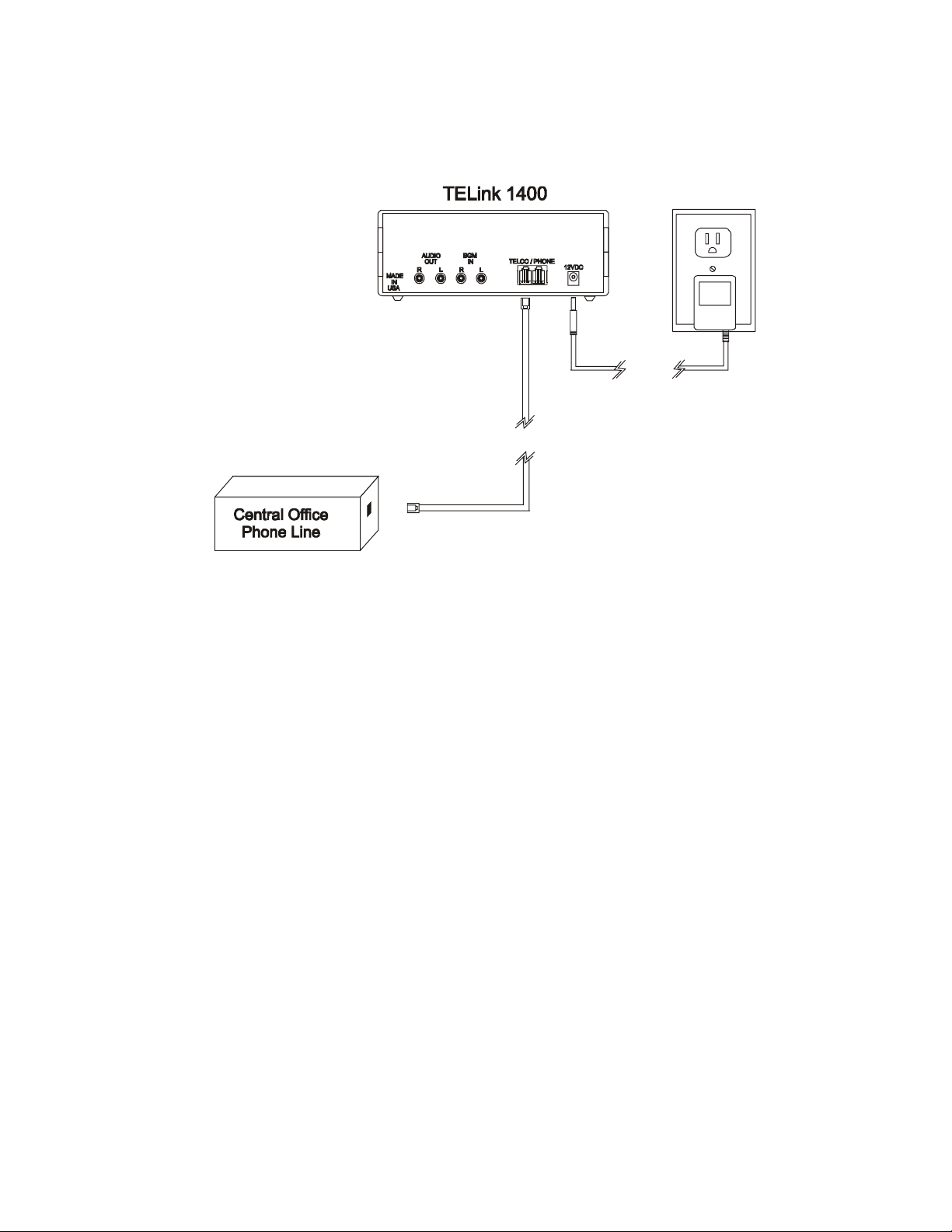
1. Make sure the power switch on the back of the TELink is OFF.
2. Connect one end of the included modular telephone cable directly to the phone company
box for the installation phone number. It is important that this cable is attached to a direct
line, prior to any other telephone equipment. The user may need to adapt one end of the
modular cable to mate to the incoming phone line.
3. Connect the other end of the modular cable to the TELCO jack on the back of the TELink.
4. Plugtheincluded12VDC powersupplyintoa110VAC walloutlet. Connecttheotherend to
the 12VDC jack on the back of the TELink.
5. Turn the power switch ON. Proceed to Audio Installation section for further instructions.
TELink 1400 Rev. 04/25/01
3.3 Telephone Installation Procedure C (Fax Share)
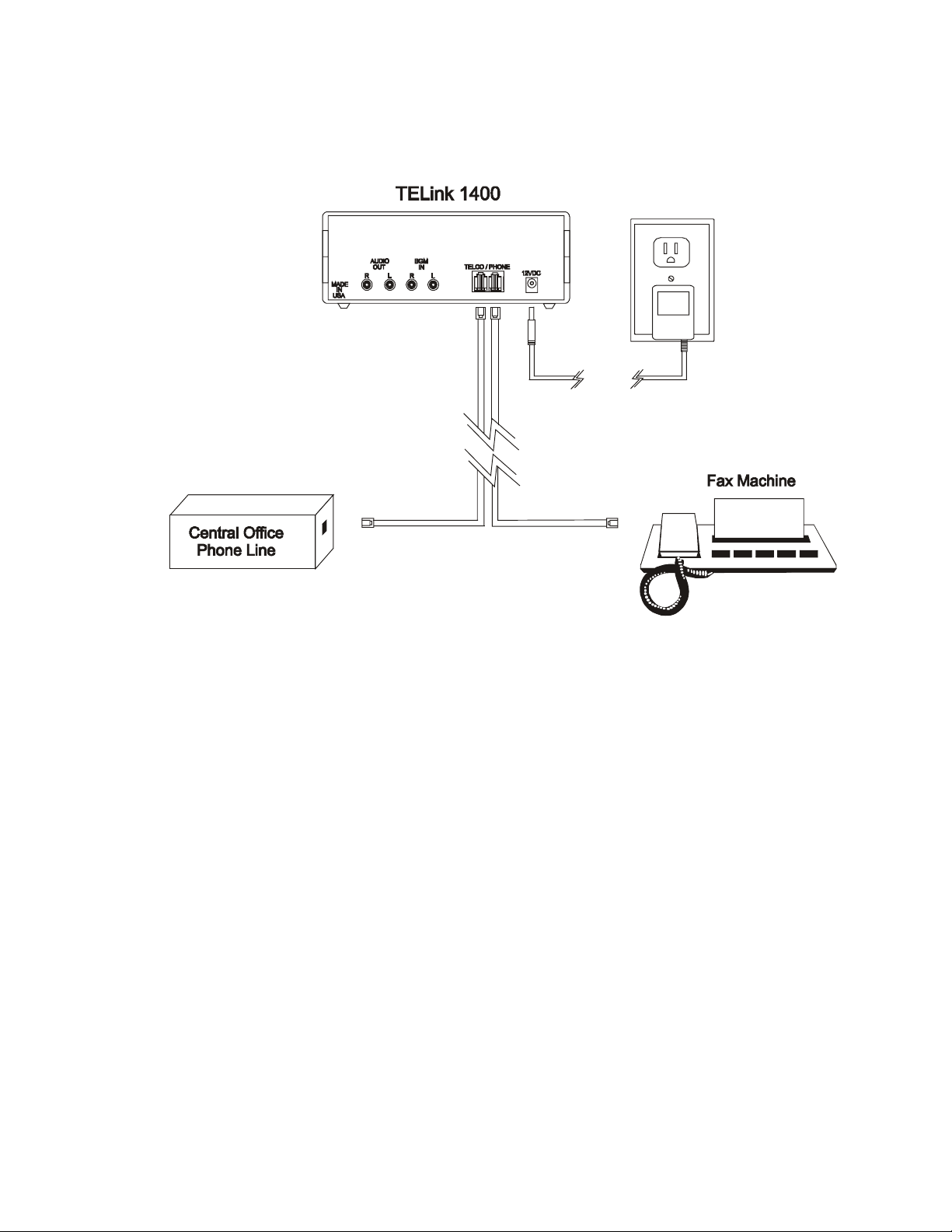
1. Make sure the power switch on the back of the TELink is OFF.
2. Connect one end of the included modular telephone cable directly to the phone company
box for the installation phone number. The TELink must be connected before the fax
machine. The user may need to adapt one end of the modular cable to mate to the
incoming phone line.
3. Connect the other end of the modular cable to the TELCO jack on the back of the TELink.
4. Usinganothermodulartelephonecable,connect the fax machine tothePHONEjackonthe
back of the TELink.
5. Plugtheincluded12VDC powersupplyintoa110VAC walloutlet. Connecttheotherend to
the 12VDC jack on the back of the TELink.
6. Set the fax machine to answer on two or more rings. The messagingprovidermust setthe
TELink to answer two rings AFTER the fax machine.
7. Turn the power switch ON. Proceed to Audio Installation section for further instructions.
3.4 Audio Installation
Table of contents


