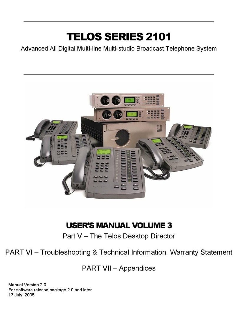
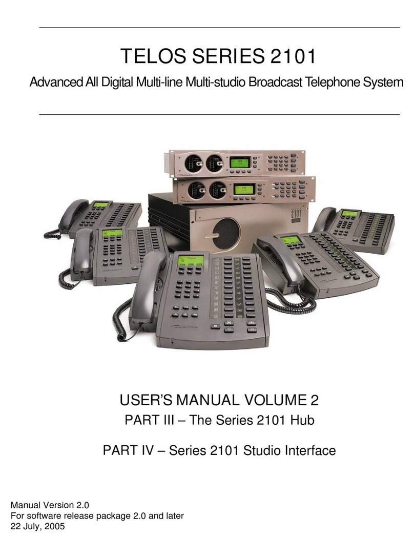
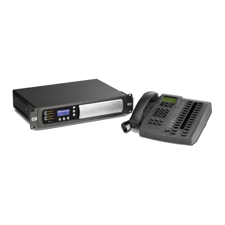
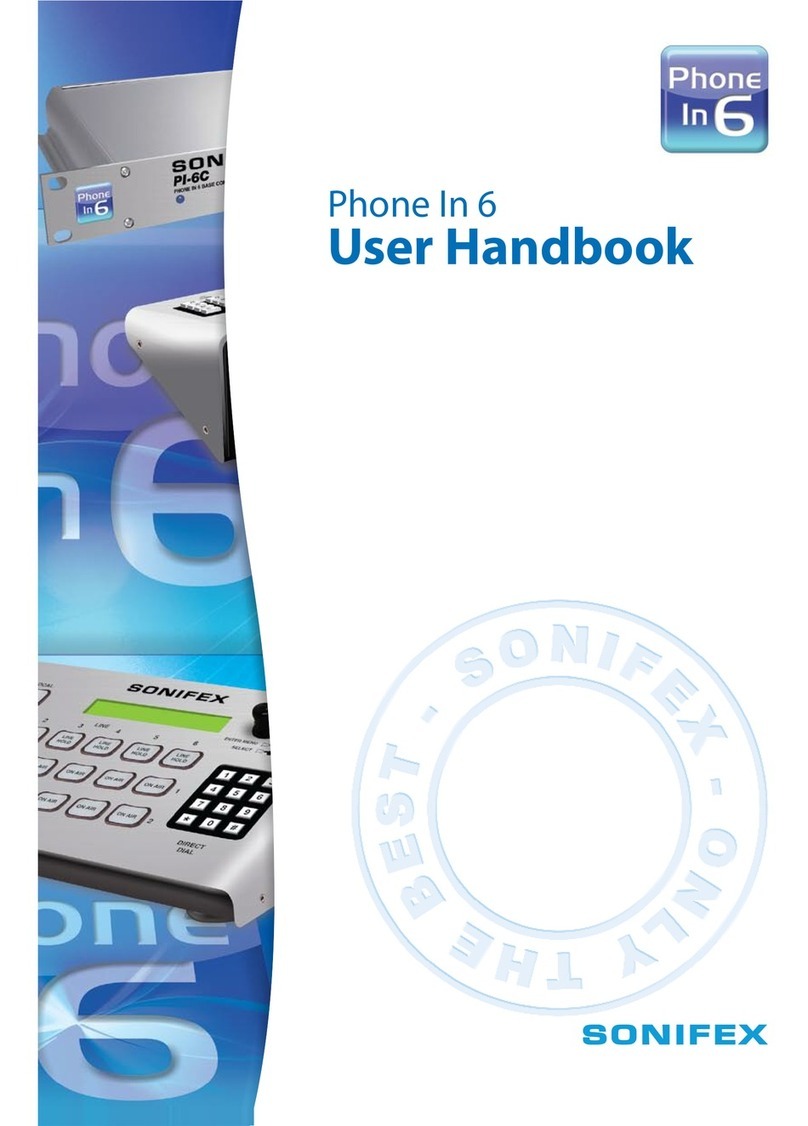
Telos DESKTOP DIRECTOR 2101 User manual

TELOS SERIES 2101
Advanced All Digital Multi-line Multi-studio Broadcast Telephone System
USER’S MANUAL VOLUME 1
Important Notes & Information, Service and Support
PART I – Introduction to the Series 2101 and its Components
PART II – Series 2101 Planning and Design
Manual Version 2.0
For software release package 2.0 and later
21 June, 2005

Customer Service
We support you...
By phone/Fax in the USA.
Customer service is available from 9:30 AM to 6:00 PM USA Eastern Time, Monday through
Friday at +1 216.241.7225. We’re often here at times outside of these, as well – please feel
free to try at any time! Fax: +1 216.241.4103.
By phone/Fax in Europe.
Service is available from Telos Europe in Germany at +49 81 61 42 467.
Fax: +49 81 61 42 402.
By E-Mail.
Via World Wide Web.
The Telos Web site has a variety of information which may be useful for product selection.
The URL is: http://www.telos-systems.com.
Feedback
We welcome feedback on any aspect of the Series 2101 or this manual. In the past, many
good ideas from users have made their way into software revisions or new products. Please
contact us with your comments.
Telos Systems
2101 Superior Avenue
Cleveland, OH 44114
USA
+1 (216) 241-7225
Fax: +1 (216) 241-4103
Telos Europe
Johannisstra βe 6
85354 Freising
Germany
+49 81 61 42 467
Fax: +49 81 61 42 402

TELOS 2101 USER’S MANUAL
III
IMPORTANT INFORMATION & NOTICES
Updates
The operation of the Telos 2101 is determined almost entirely by software. Contact
us or look on our website to determine if a newer release is more suitable to your
needs.
Trademarks
Telos Systems, the Telos logo, Desktop Director, TWO, TWOx12, and Series 2101
are trademarks of TLS Corporation. All other trademarks are the property of their
respective holders.
Copyright
Copyright © 2000, 2004, & 2005 by TLS Corporation. Published by Telos Systems,
who reserves the right to make improvements or changes in the products described in
this manual, which may affect the product specifications, or to revise the manual
without notice. All rights reserved.
Notice
All versions, claims of compatibility, trademarks, etc. of hardware and software
products not made by Telos mentioned in this manual or accompanying material are
informational only. Telos Systems makes no endorsement of any particular product
for any purpose, nor claims any responsibility for operation or accuracy.
Warranty
This product is covered by a one year limited warranty, the full text of which is
included in the Volume 3 of this manual.
Service
You must contact Telos before returning any equipment for factory service. Telos
Systems will issue a Return Authorization number, which must be written on the
exterior of your shipping container. Please do not include cables or accessories
unless specifically requested by the technical support engineer at Telos. Be sure to
adequately insure your shipment for its replacement value. Packages without proper
authorization may be refused. US customers please contact Telos technical support at
+1 (216) 241-7225. All other customers should contact your local representative to
make arrangements for service.

TELOS 2101 USER’S MANUAL
IV
IMPORTANT INFORMATION & NOTICES
Notices and Cautions
e
CAUTION:
THE INSTALLATION AND SERVICING INSTRUCTIONS IN THIS MANUAL ARE FOR USE BY
QUALIFIED PERSONNEL ONLY. TO AVOID ELECTRIC SHOCK, DO NOT PERFORM ANY
SERVICING OTHER THAN THAT CONTAINED IN THE OPERATING INSTRUCTIONS UNLESS
YOU ARE QUALIFIED TO DO SO. REFER ALL SERVICING TO QUALIFIED PERSONNEL.
e
WARNING:
TO REDUCE THE RISK OF ELECTRICAL SHOCK, DO NOT EXPOSE THIS PRODUCT
TO RAIN OR MOISTURE. DO NOT SHOWER WITH THE UNIT.
This symbol, wherever it appears, alerts you to the presence
of uninsulated, dangerous voltage inside the enclosure –
voltage which may be sufficient to constitute a risk of shock.
This symbol, wherever it appears, alerts you to important
operating and maintenance instructions. Read the manual.
TO PREVENT RISKS OF
ELECTRIC SHOCK,
DISCONNECT POWER
CORD BEFORE SERVICING
USA CLASS A COMPUTING DEVICE INFORMATION TO USER. WARNING: This
equipment generates, uses, and can radiate radio-frequency energy. If it is not installed and
used as directed by this manual, it may cause interference to radio communication. This
equipment complies with the limits for a Class A computing device, as specified by FCC Rules,
Part 15, Subpart J, which are designed to provide reasonable protection against such
interference when this type of equipment is operated in a commercial environment. Operation of
this equipment in a residential area is likely to cause interference. If it does, the user will be
required to eliminate the interference at the user’s expense. NOTE: Objectionable interference
to TV or radio reception can occur if other devices are connected to this device without the use
of shielded interconnect cables. FCC rules require the use of only shielded cables.
CANADA WARNING: “This digital apparatus does not exceed the Class A limits for
radio noise emissions set out in the Radio Interference Regulations of the Canadian
Department of Communications.” “Le present appareil numerique n’emet pas de bruits
radioelectriques depassant les limites applicables aux appareils numeriques (de Class A)

TELOS 2101 USER’S MANUAL
V
IMPORTANT INFORMATION & NOTICES
prescrites dans le Reglement sur le brouillage radioelectrique edicte par le ministere des
Communications du Canada.”
Warning and Cautions About the Telco Interface Cards Used in this System
FCC Part 68 Notice for T1 Interface Model PRI-PCI
This equipment complies with Part 68 of the FCC Rules. On the surface of the circuit
side of the printed circuit board of this equipment is a label that contains, among
other information, the FCC Registration Number and Ringer Equivalence Number
(REN), if applicable, for this equipment. If requested, this information must be
provided to the telephone company.
This equipment uses two (2) RJ-48 8-pin modular registered jacks. This equipment is
designed to be connected to the telephone network or premises wiring using a
compatible modular plug which Part 68 compliant. When ordering Primary Rate
ISDN service for this product the following information should be given to your
service provider:
-Extended Superframe (ESF) framing and B8ZS Line coding
-Each B-channel provisioned for alternate circuit-switched data/circuit-switched
voice (CSD/CSV)
-The D-channel must be on channel 24 of the line
-No Packet handlers other than the D-channel
-64kbps clear channel service end-to-end for every call
Refer to the appropriate section in the User Guide concerning ISDN service
provisioning for additional information.
If the PRI-PCI terminal equipment causes harm to the telephone network, the
telephone company will notify you in advance that temporary discontinuance of
service may be required. But if advance notice is not practical, the telephone
company shall notify the customer as soon as possible. Also you will be advised of
your right to file a complaint with the FCC if you believe it is necessary.
The telephone company may make changes in its facilities, equipment, operation or
procedures that could affect the operation of your equipment. If this happens the
telephone company will provide advance notice in order for you to make the
necessary modifications in order to maintain uninterrupted service.
If trouble is experienced with the PRI-PCI, please contact Telos Systems (see above)
or;
Warranty and Repair Service Center
Netaccess, Inc
18 Keewaydin Dr
Salem, NH 03079
603 890-7298

TELOS 2101 USER’S MANUAL
VI
IMPORTANT INFORMATION & NOTICES
for repair and (or) warranty information. If the trouble is causing harm to the
telephone network, the telephone company may request that you remove the
equipment from the network until the problem is resolved.
The PRI-PCI does not contain users repairable or serviceable components.
This equipment may not be used on the publish coin service provided by the
telephone company. Connection to Party Line Service is subject to state tariffs.
The PRI-PCI is a DSX-1 device. Federal regulations (FC Part 68) prohibit connection
of a DSX-1 device to the network without an FCC approved Channel Service Unit
(CSU). Customers connecting this device to the network shall upon request of the
telephone company, inform the telephone company of the particular lines to which
such connections are made and the FCC registration of the protection device (CSU).
INDUSTRY CANADA (IC) NOTICE (Canada)
“NOTICE: The Industry Canada (IC) label identifies certified equipment. This
certification means that the equipment meets telecommunications network protective,
operational and safety requirements as prescribed in the appropriate Terminal
Equipment Technical Requirements document(s). The department does not guarantee
the equipment will operate to the user’s satisfaction.
Before installing this equipment, users should ensure that it is permissible to be
connected to the facilities of the local telecommunications company. The equipment
must also be installed using an acceptable method of connection. The customer
should be aware that compliance with the above conditions may not prevent
degradation of service in some situations.
Repairs to certified equipment should be coordinated by a representative designated
by the supplier. Any repairs or alterations made by the user to this equipment, or
equipment malfunctions, may give the telephone communications company cause to
request the user to disconnect the equipment.
Users should ensure, for their own protection, that the electrical ground connections
of the power utility, telephone lines and internal metallic water pipe system, if
present, are connected together. This precaution may be particularly important in
rural areas.
CAUTION: Users should not attempt to make such connections themselves, but
should contact the appropriate electrical inspection authority, or electrician, as
appropriate”
“This Class (A) digital apparatus meets all requirements of the Canadian
Interference-Causing Equipment Regulations”
“Cet appareil nume’rique de classe (A) respecte toutes les exigences du Regulement
sur le mate’riel brouilleur du Canada”
EUROPEAN UNION NOTICES
To ensure compliance with EN 60950: 1992, you must follow the requirements
below when installing a PRI-PCI board:
Power
•The PC chassis must supply power to the board according to the power
requirements listed elsewhere
TELOS 2101 USER’S MANUAL
VII
IMPORTANT INFORMATION & NOTICES
•The total power required by the host processor, PRI-PCI board(s) and other
boards in the PC chassis must not exceed the power specifications in the PC’s
technical manual.
Hazardous Voltage
•Typical, a PRI-PCI board is not installed in a PC chassis that contains boards
which use or generate hazardous voltage (voltages that exceeds 42.4 Vac or 60
Vdc at peak condition). If you believe hazardous voltages is present in the PC
chassis, contact Netaccess Customer Support for assistance when installing a
PRI-PCI board.
Interface Connections
•All PRI-PCI board interfaces possess a SELV safety classification for connection
to other devices.
•PRI-PCI boards must not be used in conjunction with other equipment to switch
messages, producing two-way live speech calls, except where such use is
explicitly permitted by the approval of the other equipment.
Clearance & Creepage Distances
•The PRI-PCI board must be installed with appropriate clearance and creepage
distances between the board and any device that uses or generates voltage (other
than PCI bus connections). The table below identifies the minimum distances
according to the voltage used or generated by the device:
Voltage Used/Generated Clearance Creepage
Up to 50 Vrms/Vdc 2.0 mm 2.4 mm (3.8 mm)
Between 50 and 125 Vrms/Vdc 2.6 mm 3.0 mm (4.8 mm)
Between 125 and 250 Vrms/Vdc 4.0 mm 5.0 mm ( 8.0 mm)
Between 250 and 300 Vrms/Vdc 4.0 mm 6.4 mm (10.0 mm)
Greater than 300 Vrms/Vdc Obtain advice from a competent
telecommunications safety engineer
before installing the board
NOTE: if the PC chassis is subject to conductive pollution or dry nonconductive pollution which
may become conductive due to condensation, use the creepage distances specified in brackets.
GERMAN NOTICE
The edge connector that is intended for connection to the host PC is a Safety Extra
Low Voltage (SELV) circuit. Rechnerschnittstelle: Der Kontakleiste der die
Verbindung Zum PC herstellt entspricht den Safety Extra Low Voltage (SELV)
Bestimmungen.
AUSTRALIAN NOTICE
WARNING- This equipment will be inoperable when mains power fails!
“Connection of this equipment must be made via an AUSTEL certified or permitted
Line Isolation Unit”.

TELOS 2101 USER’S MANUAL
VIII
IMPORTANT INFORMATION & NOTICES
This customer equipment is to be installed and maintained by service personnel as
defined by AS/NZS 3260 Clause 1.2.14.3 (Service Personnel). Incorrect connection
of connected equipment to the General Purpose Outlet could result in a hazardous
situation.
Safety requirements are not fulfilled unless equipment is connected to a wall socket
outlet with protective earth contact.

TELOS 2101 USER’S MANUAL
IX
IMPORTANT INFORMATION & NOTICES
User’s Manual Table of Contents
Warning and Cautions About the Telco Interface Cards Used in this System..................................v
User’s Manual Table of Contents....................................................................................................ix
Conventions used in this manual ......................................................................................................x
Table of Contents for Part I..............................................................................................................3
PART I - INTRODUCTION TO THE SERIES 2101 AND ITS COMPONENTS I-1
PART II - SERIES 2101 PLANNING, DESIGN, & COMMISSIONING II-1
PART III - THE SERIES 2101 HUB III-1
PART IV - THE STUDIO INTERFACE & ADDITIONAL HYBRIDS IV-1
PART V - THE DESKTOP DIRECTORS V-1
PART VI - TECHNICAL INFORMATION AND TROUBLESHOOTING VI-1
PART VII – APPENDICIES VII-1
APPENDIX 1 – TELEPHONE TECHNOLOGY TUTORIAL
APPENDIX 2 – GLOSSARY OF TELEPHONE TECHNOLOGY
APPENDIX 3 – MODULAR CABLE GUIDE
APPENDIX 4 – SUGGESTED READING
APPENDIX 5 – ORDERING DIGITAL TRUNKS FOR USE WITH SERIES 2101

TELOS 2101 USER’S MANUAL
X
IMPORTANT INFORMATION & NOTICES
A word about this manual
This manual is written in seven parts, as shown on the previous page. The parts are
identified with the Roman numerals I through VII. It is bound as three volumes. The
first volume, the volume you are reading, contains important safety information and
compliance information as well as how to contact Telos (see pages III-IX,
preceding).
The following symbols are used throughout this manual to highlight various type of
information contained within.
e
DANGER!
This information is important to safe operation of the equipment and warns of
possible hazards. For you safety you should read these.
w
IMPORTANT!
This information is essential to getting the Series 2101 to work, or prevent damage to
it. To avoid headaches read these.
h
HOT TIP!
This information will probably come in handy at some point. You will probably wish
to read these.
i
ISDN TIP!
Important information about ISDN. This is recommended reading for all ISDN users.

TELOS 2101 USER’S MANUAL
XI
IMPORTANT INFORMATION & NOTICES
c
MIX- MINUS TIP!
Information useful when configuring your send- to- caller Mix- Minus feeds.
t
DEEP TECH NOTE!
Amaze your technical friends with your voluminous knowledge of the 2101, ISDN,
and hybrid technology! Not necessary for the ability to install and use the 2101, but
this information might come in handy if you ever need to troubleshoot the system.
?
CURIOSITY NOTE!
Amaze your friends with your grasp of ISDN and Hybrid trivia. Not necessary for the
ability to install and operate the 2101.

TELOS 2101 USER’S MANUAL
XII
IMPORTANT INFORMATION & NOTICES
This page intentionally left blank for formatting purposes.

TELOS SERIES 2101
Advanced All Digital Multi-line Multi-studio Broadcast Telephone
System
USER’S MANUAL
PART I
Introduction to the Series 2101 and its Components
V2.0c

TELOS 2101 USER’S MANUAL
PART I
INTRODUCTION TO THE SERIES 2101 & COMPONENTS
I-2
TABLE OF CONTENTS
This page intentionally left blank

TELOS 2101 USER’S MANUAL
Table of Contents for Part I
1 WHY THE SERIES 2101?................................................................................................................... 5
1.1 FIRST OF ALL,JUST WHAT IS THE SERIES 2101?............................................................................... 5
1.2 FEATURES AND BENEFITS OF THE SERIES 2101................................................................................ 5
1.3 WHY DIGITAL TRUNKS MAKE SENSE FOR BROADCAST TALK SHOW SYSTEMS .............................. 6
2 SO WHAT IS SERIES 2101? (SYSTEM COMPONENTS)........................................................... 11
2.1 THE 2101 HUB .............................................................................................................................. 11
2.2 2101 STUDIO INTERFACE............................................................................................................... 12
2.3 TELOS TWO HYBRID .................................................................................................................... 13
2.4 DESKTOP DIRECTOR ™ ................................................................................................................. 14
2.5 ETHERNET 10/100 BASE-T LAN HUB ........................................................................................... 15
2.6 ASSISTANT PRODUCER FOR 2101 CALL SCREENING SOFTWARE .................................................. 15
2.7 PUTTING IT ALL TOGETHER.(A SAMPLE CONFIGURATION)........................................................... 16

TELOS 2101 USER’S MANUAL
PART I
INTRODUCTION TO THE SERIES 2101 & COMPONENTS
I-4
TABLE OF CONTENTS
This page was intentionally left blank

TELOS 2101 USER’S MANUAL
PART I
INTRODUCTION TO THE SERIES 2101 & COMPONENTS
I-5
SECTION 1 – WHY THE 2101?
1Why the Series 2101?
If you have already purchased the Series 2101 Telephone System, you may not need
further discussion of why it was a good idea. However, you may be reading this
manual prior to deciding if the Series 2101 is right for you. This section can also help
you get the best performance out of your system, since it highlights the system’s
capabilities.
1.1 First of all, just what is the Series 2101?
The Telos Series 2101 is designed for broadcast facilities where dozens of incoming
talk lines are required and those lines are required to be shared among multiple
studios. Depending on the version ordered, the 2101 Hub can interface to as many as
four T1 circuits (24 channel digital circuits as used in North America and Japan), E1
circuits (30 channel digital circuits as used in most other areas of the world), or ISDN
PRI (Primary Rate Interface) circuits based on E1 or T1.
The 2101 supports up to 32 multiple studios. Each Studio typically has a single Telos
2101 Studio Interface that contains two all-digital telephone hybrids. Four-hybrid
studio configurations are also possible, consisting of a Telos 2101 Studio Interface
plus a Telos TWO all digital dual hybrid.
At the heart of any broadcast telephone system are the hybrids used. Based on the
Telos TWO dual hybrid, the 2101 Studio Interface includes simply the best broadcast
hybrids made. With a trans-hybrid loss of well over 70dB, it allows for the best
possible announcer audio over the air. Performance when used with open speakers
and in teleconferencing applications is also superb.
The 2101 combines this hybrid design with a multi-line system controller (the Series
2101 hub) and multiple studio interfaces. Each 2101 Studio Interface offers support
for up to two (expandable to eight) Telos Desktop Director control surfaces -
typically one for a phone screener and one for talent. Each Desktop Director can be
can be easily reconfigured between the talent and producer (screener) modes of
operation and to select the a “show configuration” for that studio. The Desktop
Director has an intuitive user interface and we are confident your staff will take to the
system in no time.
If it sounds like we are proud of this system, you are right! We appreciate the
opportunity to take your facility into the 21st Century.
1.2 Features and benefits of the Series 2101
Telos products have earned a reputation for ease of use and outstanding performance,
and the Telos Series 2101 lives up to that reputation. Our advanced ISDN hybrid
technology comprises an integrated suite of audio processing functions to achieve
unsurpassed audio quality.
Up to 120 incoming Telco Channels (depending on the type of Telco connections
used)
Systems available with support for up to 32 studios

TELOS 2101 USER’S MANUAL
PART I
INTRODUCTION TO THE SERIES 2101 & COMPONENTS
I-6
SECTION 1 – WHY THE 2101?
Dual-redundant Hubs can be used to protect against the loss of a hub or any
Telco Trunk (Please consult your Telos Sales Engineer for additional information
on this option).
Multiple “show configurations” each of which determines the number of active
lines. Studio configurations can be changed easily – No more “programming”
with a punch tool.
Any phone number can ring in any studio. Using PRI trunks hunt groups can be
created. Number/Line assignments can be dynamically changed.
Studio-grade 20-bit A-to-D conversion, combined with noise gating and shaping,
guarantees crystalline audio to the caller and significantly improved send levels.
Simultaneous analog and AES/EBU outputs.
Automatic high-precision sample rate conversion for incoming AES/EBU.
Unmatched Send/Receive separation using Telos’ time-tested Adaptive
Cancellation technology. Each hybrid automatically & continuously adjusts to
phone line conditions, virtually eliminating the hollowness, feedback and
distortion that occurs when send audio “leaks” into the caller output signal.
Sophisticated AGC/limiting functions and three-band Digital Dynamic
Equalization (DDEQ) ensure consistent caller audio levels and spectral
consistency.
Easy to use menus. Full metering for proper setup and operation.
Caller ID* support and fully adjustable Caller Ducking (override) helps hosts
stay in control (PRI only).
*Caller ID service required from your Telco service provider.
Conference linking ability lets you set up high-quality conferencing between
callers with no external equipment needed. (Only a single mix-minus is
required.)
1.3 Why Digital Trunks Make Sense for Broadcast Talk Show Systems
We’d like to highlight the advantages of using digital telephone trunks such as E1,
T1, and PRI for interfacing your studio to the outside world. Our website at
http://www.telos-systems.com has several papers dedicated to this subject as well.
Digital Trunks including ISDN are widely available, cost-effective, and offer many
advantages for studio systems. It is yet another example of digital technology
enhancing broadcast operations.
Integrated Services Digital Network (ISDN) is a set of international standards for
digital transmission over ordinary telephone copper wire (as well as over other
media). Presently, the dial-up telephone network is nearly entirely digital, except for
the “last mile” copper connections from the Central Office (Exchange) to the
customer’s site. The Series 2101 takes advantage of this technology to deliver crystal
clear caller audio to the radio studio.
The telephone network routes calls over 64 kbps channels. A sampling rate of 8 kHz
is used, with a word length of 8 bits. The 8 kHz sampling rate supports a Nyquist
(audio cut-off) frequency of 4 kHz. In practice, telephone systems are designed to

TELOS 2101 USER’S MANUAL
PART I
INTRODUCTION TO THE SERIES 2101 & COMPONENTS
I-7
SECTION 1 – WHY THE 2101?
have audio frequency response extending to 3.4 kHz in order to allow relatively
simple roll-off filters to be used.
?
CURIOSITY NOTE!
The word length is what determines dynamic range–and 8 bits would only permit 48
dB were it used in standard PCM linear fashion. A primitive kind of compression is
used to stretch the dynamic range: µLaw in North America and much of Asia, and A-
law in Europe. This is a scheme that equalizes the step- size in dB terms across the
dynamic range–a smaller step- size on low- level signals reduces quantization noise
and improves effective dynamic range to the equivalent of about 13 bits. The correct
setting is covered in Part IV (Studio Interface & Additional Hybrids).
While the application of digital signal processing to the problem of separating host
and caller audio – pioneered by Telos and used in all of our telephone interfaces –
has made a dramatic improvement over pure analog systems, using digital phone
lines for incoming calls further improves performance for several reasons:
ISDN Lines are Inherently “4-wire”
Analog lines use a single pair of wires for both signal directions, mixing the send and
caller audio. This causes the “leakage” problem–where the announcer’s audio is
present on the hybrid output, where we desire that there only be caller audio. A “4-
wire” circuit has two wire pairs, and therefore two independent audio paths. Digital
circuits inherently offer independent and separated signal paths because it is not
possible to have bits moving in both directions without separating them somehow.
(Though a digital circuit may today not use wires at all, but rather fiber, microwave
radio, or satellite, telephone engineers, bowing to tradition, continue to refer to all
separated speech paths as being “4-wire.”)
While the application of DSP to the problem of separating the signals–used in digital
hybrid interfaces–has made a dramatic improvement over analog systems, ISDN
enables yet further improved performance.
Better Digital-Analog Conversion Quality
The analog-digital conversion chips used in telephone central offices are poor
compared to the converters used in professional audio equipment. Fidelity is not an
important consideration when most Telco equipment designers choose parts for this
function. In a professional interface for studio applications such as the Series 2101
Studio Interface, we can afford to design-in much better converters than available in
the Telephone Company’s equipment. Noise-shaping functions permit a larger word-
length converter to provide significantly better distortion and signal-to-noise
performance.
Since we are handling the conversion, we can encode at higher levels without
concern about regulations designed to prevent crosstalk on analog lines, resulting in
improved send-to-caller levels.
In all-digital installations, the telephone interface can maintain a digital path all the
way. AES/EBU is included in the 2101 Studio Interface to accomplish the connection
to digital studio gear.

TELOS 2101 USER’S MANUAL
PART I
INTRODUCTION TO THE SERIES 2101 & COMPONENTS
I-8
SECTION 1 – WHY THE 2101?
Lower Noise
Because they are digital circuits, digital lines are not susceptible to induced noise.
Analog lines are exposed to a variety of noise and impulse trouble-causers as they
move across town on poles and through your building. Hum is the main one, given
most line’s proximity to pole transformers and power lines, but there are also sources
of impulse noise from motors, switches, and other sources. Digital lines convey the
bits precisely and accurately from the network to your studio equipment without any
perturbation–so the audio remains clean. Even when the caller is using an analog
phone line to call in, the noticeably quieter digital connection between the hybrid and
the telephone network helps the hybrid achieve better rejection of outgoing audio
leakage.
Call Setup and Supervision are Better
Analog lines use a strange mix of signaling to convey call status. Loop current drop
and returned dial-tone signal that a far-end caller has disconnected; blasts of 100
volts at 20 Hz mean someone wants you to answer. Why should we be using a
mechanism designed to bang a hammer against a metal bell to transmit network
status information into the 21st Century? ISDN uses a modern digital approach to
controlling calls and conveying status information about them. The sophisticated
transactions on the D channel are able to keep both ends of a call accurately informed
about what is happening.
For starters, ISDN call set-up times are often only a few 10’s of milli-seconds,
enhancing production of a fast-paced show. Perhaps more importantly, when a caller
disconnects while waiting on hold, the ISDN channel communicates this status
change instantly. This contrasts with the usual 11-second delay on most analog lines.
One of the most common complaints of talk hosts is that they go to a line where they
expect a caller to be waiting, only to be met with a blaring, annoying dial tone. The
chance of this happening with an ISDN line is nearly zero.
Another common error is the condition where a talent punches-up a line that looks
free, but which actually is just about to begin ringing and connects to a surprised
caller. This condition, called glare, results from the delay in the ring signaling, which
comes from the nature of the analog line’s ringing cadence. This is much less likely
with ISDN because it eliminates the ambiguous status period.
?
CURIOSITY NOTE!
We don’t know why the condition of picking up a line which was about to ring and
getting an incoming call instead of dial tone is called “Glare”. Perhaps its because the
looks air staff give engineers when this happens too often!
If you find out, be sure to let us know!
Higher Gain and Reduced Feedback During Multi-line Conferencing
Higher Gain and Reduced Feedback During Multi-line Conferencing. When
conferencing is required on 2-wire circuits, very good hybrids are needed to separate
the two audio paths in order to add gain in each direction. When the gain around the
loop exceeds unity, the unpleasant result is feedback. Since the conference path
usually includes four AGC functions, the hybrid must be sufficiently good to cover
the additional gain that may be dynamically inserted by these AGC’s.
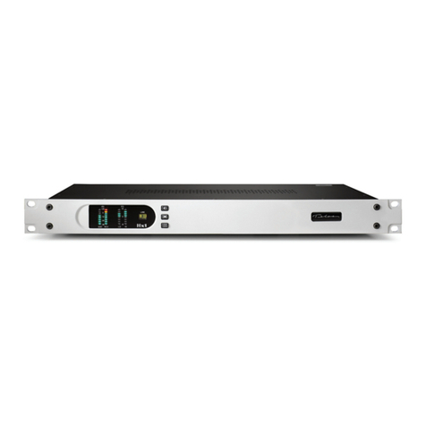
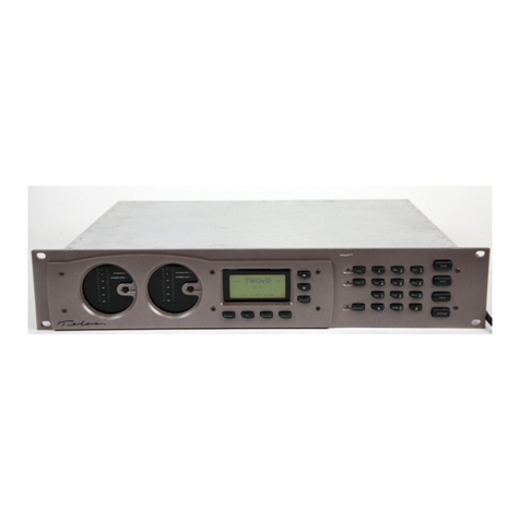
Other manuals for DESKTOP DIRECTOR 2101
2
Table of contents
Other Telos Telephone System manuals
Popular Telephone System manuals by other brands

AVT
AVT MAGIC TH1 potsGo Configuration guide

Sprint
Sprint SP7084 owner's manual

Vodavi
Vodavi Starplus Triad 1/2/3 installation manual

Lucent Technologies
Lucent Technologies MERLIN LEGEND Release 6.0 Pocket reference

Samsung
Samsung DCS-816 System administration and special features guide

AT&T
AT&T MERLIN LEGEND Key system planning