tell BASE 1000 User manual
For device version v8.00 (29.07.2021)
Gate Control BASE 1000
QUICK GUIDE FOR INSTALLERS
Dear Customer!
Thank you for choosing our product. The full Installation
and Application Manual is available on our website at:
https://tell.hu/en/products/gsm-automation/gate-control-base
GENERAL OPERATION OF THE GATE CONTROL BASE:
The Gate Control BASE device was basically designed for control of electric
gates and barriers. However, it can be used to control other devices as well.
Controlling can be performed according to the configured control mode by
making a phone call to the number of the SIM card installed into the device.
For compatibility with most gate automation control boards, upon setup you can
choose out of 5 different control modes, the one which is appropriate for your
gate automation. When controlling the system by call, it uses caller identification
to identify the caller/user.
Controlling (opening/closing) is possible only from authorized phone numbers
registered in the device, or from any phone number, according to the
configuration: if there are users registered with phone numbers in the user
list, only calls from these phone numbers can control the device. If there
are no users registered, calls from any phone number will control the
device. If you use output control mode No. 1, calls from a private (hidden)
number will control output OUT2 in any case.
The system supports up to 1000 users, for which different options and
permissions can be configured, such as role, 0-24 entry period, and access to
outputs (gates), depending on the output control mode chosen.
Users who are granted the 0-24 entry period permission can control the system
anytime, while users who are not granted this permission can control the system
over the day only within the time interval configured in the Permitted entry
period section in the General device settings menu. If there are no users
registered in the device, the system can be controlled by anyone from any phone
number only within the configured permitted entry period.
2
PUTTING INTO OPERATION:
1. Choose the SIM card services according to the device functions you would
like to use (mobile Internet, voice call, SMS service).
2. Enable caller identification service on the SIM card at the mobile service
provider.
3. Disable voice mail and notification about missed calls on the SIM card.
4. If you want to lock the SIM card with a PIN code, you will have to provide the
PIN code in the device settings. Otherwise, disable PIN code request on the
SIM card.
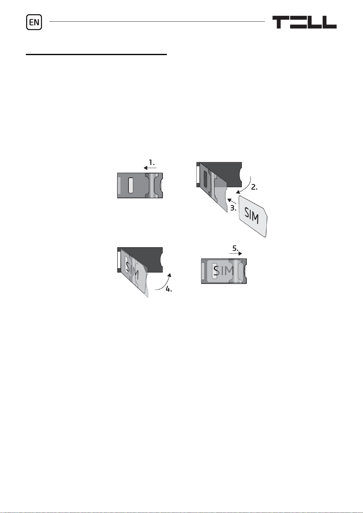
5. Remove the SIM card bay cover of the device and install the SIM card.
6. Check the installation environment for avoiding weak signal and other
problems (strong electromagnetic disturbances, high humidity).
7. Connect the antenna.
8. Do the wiring according to the control mode chosen.
9. Connect the device to the power supply (12-30V AC/DC, 500mA).

Gate Control BASE 1000 Quick guide
3
Attention! Do NOT connect the connector of the antenna directly or
indirectly to the protective ground, because this may damage the device!
-> Chapter 1, 3.5 and 3.8 of the Installation and Application Manual.
DEVICE WIRING:
The Gate Control BASE has four inputs and two outputs, which can be
configured in the programming software for the task at hand.
Inputs:
The NO or NC dry contacts should be connected between the selected input and
the V- supply voltage negative terminal.
The device can send SMS with configured messages or make calls to configured
phone numbers upon triggering the inputs.
Outputs and control modes:
The outputs provide normally open (NO) dry contacts as the default state,
and closed contacts when controlled, except for control mode No. 3, where
output OUT2 is normally closed (NC). They can take a load of 1A@24V AC/DC.
The device supports five different output control modes for compatibility with
most gate automation control boards. Choose the control mode appropriate for
your gate automation.
Control mode 1:
- For one or two gates, or one
gate with two opening options
(partial/ total opening).
- Both outputs are normally
open (NO).
- OUT1 is controlled by call with
caller identification.
- OUT2 is controlled by calls
from private (hidden) number.
- A control call only opens the
gate. Closing should be done
automatically by the gate
automation control board.

4
Control mode 2:
- For one or two gates, or one gate with two opening options (partial/ total
opening).
- Both outputs are normally open (NO).
- Both outputs are controlled by call with caller identification as configured
(OUT1 only, OUT2 only, or both at the same time).
- Output control permission can be configured separately for each user and
each output.
- A control call only opens the gate. Closing should be done automatically by
the gate automation control board.
Control mode 3:
- For single-gate automations
that require triggers for
opening and closing on the
same input.
- Opening and then closing by
a single call.
- Output OUT1 is normally open
(NO), while OUT2 is normally
closed (NC).
- Output OUT1 is used to
control the gate, while OUT2
is used to interrupt the
photocell sensor circuit,
thereby providing an option to
keep the gate open for the
configured period of time.
- Keeping the gate open permanently on a second call.

Gate Control BASE 1000 Quick guide
5
Control mode 4:
- For single-gate automations
that require triggers for opening
and closing on different inputs.
- Opening and then closing by
a single call.
- Both outputs are normally open
(NO).
- The opening trigger is provided
by output OUT1 and the closing
trigger is provided by output
OUT2.
- Keeping the gate open
permanently on a second call.
Control mode 5:
- For single-gate automations
that require triggers for opening
and closing on different inputs.
- Opening and then closing by separate calls.
- Both outputs are normally open (NO).
- The opening trigger is provided by output OUT1 and the closing trigger is
provided by output OUT2.
-> Chapter 3, 5.2.2 and 5.2.5 of the Installation and Application Manual.
STATUS LED SIGNALS:
Slowly flashing green
Normal operation,
connected to the mobile network
Flashing red
The mobile service is unavailable,
or system startup/restart is in progress
Permanent red
SIM card error

6
PROGRAMMING SOFTWARE:
The latest version of the programming software is available on the
manufacturer’s website.
Connecting via USB :
- Launch the Gate Control programming software.
- Power up the device and then connect it to the computer using a USB A-B
cable.
- Select the USB option in the Connection type menu.
- Enter the USB connection password (default password: 1234), then click on
the Connect button.
- In order to configure the settings, first you need to read the actual settings
stored in the device. For this, click on any menu item in the Device settings
group and read the settings by clicking on the Read settings button.
- Configure the settings as needed, and then write the changed settings into the
device by clicking on the Write settings button.
APN, PIN code, and Cloud:
In order to access the device remotely over the Internet, the APN needs to be
configured in the SIM settings section in the General device settings menu.
If you want to lock the SIM card with a PIN code, then enter the PIN code of the
SIM card in the SIM settings section and enable PIN code request on the SIM
card.
Remote access works through cloud service. In case of using a SIM card that
uses a private APN, accessing the cloud server IP address in the given APN
must be specifically enabled at the mobile service provider. The cloud
availabilities are the following:
Server address: 54.75.242.103 Server port: 2016

Gate Control BASE 1000 Quick guide
7
Registering the super administrator and configuring a remote
access:
For full access to remote programming, it is necessary to configure a user with
Super admin role, and a remote access password for that user. New users can
either be added in the Users menu as follows, or by SMS:
- In order to add users, first you need to read the settings and users stored in
the device. For this, click on the Read users button in the Users menu.
- Add a new user by clicking on the Add new button.
- Type in the user’s Name and Phone number.
- Set the Role to Super admin, configure the Permissions as needed, click on
the OK button when finished, and then click on the Write users button to
write the user into the device.
- Switch to the Remote access menu and then click on the Add new button
to configure a password for remote access.
- Select the User from the drop-down menu and enter the Password that you
want to use when signing in for remote programming, and then click on the OK
button.
- Click on the Write users button to update the settings in the device.
All data can be changed later, except the user’s name. If you need to change the
name, you have to delete the user and add it again.
Configuring a system administrator:
In most applications, a separate administrator is needed for managing users in
the Gate Control BASE., in order to relieve the super administrator. You can
add administrators by following the steps specified above, but choosing the
Admin option for Role.
Specification of user roles:
- User: can only control the system.
- Admin: can control the system, manage users (add/modify/delete), and
command the device to connect to the cloud.
- Super admin: full permission, can control the system and manage users and
settings, and command the device to connect to the cloud.
8
Registering the Super administrator, the administrator, or users by
SMS:
If you don't want to use the PC software, there is a quick way to add the super
administrator, the administrator, or users by SMS. You can register yourself as
super administrator by sending one of the following commands by SMS to the
phone number of the device, depending on your choice:
SUPERADMIN# - this command will add you in the device with the user
name “SUPERADMIN”and your phone number.
SUPERADMIN=NAME# - this command will add you in the device with the
user name typed instead of NAME and with your phone number.
n=TELNUMBER,NAME,ROLE,ENTRY PERIOD,GATE# - this command will
add you in the device with details:
TELNUMBER: replace this with your phone number
NAME: replace this with your name
ROLE: replace this with your role (S=super admin, A=Admin, U=user)
ENTRY PERIOD: replace this with your entry permission (N=0-24,
L=only in the configured entry period)
GATE: replace this with your output control permission (1=OUT1, 2=OUT2,
B=both OUT1+OUT2 at the same time)
Example: n=+3630xxxxxxx,John Smith,S,N,1#
The device will accept the registration of the very first super administrator
or administrator automatically. Further administrators and users can only
be added by registered super administrators or administrators.
For a detailed explanation of the user management, please read the Installation
and Application Manual.
Registering the device identifier:
The device can be identified and accessed remotely based on its unique device
identifier. You can read and copy the device ID to clipboard in the Status
monitoring menu.
You can store the device availabilities (name, device identifier, comments) using
the Add new button in the Device register menu, which will help you later,
when you want to access the device remotely.
Gate Control BASE 1000 Quick guide
9
Remote access :
The Gate Control BASE device does not keep continuous connection with the
cloud, it only connects to the server upon request. Therefore, before trying to
connect remotely to the device, the request for connecting to the cloud should
be sent by SMS to the phone number of the SIM card installed in the device:
CONNECT#
The device accepts the command for connecting to the cloud from Admin and
Super admin users only.
- Launch the Gate Control programming software.
- Click on the Connection type menu and select the Cloud option.
- If you have already registered the availabilities of the device in the Device
register menu, select the device you want to connect to in the Device name
drop-down menu. Otherwise, enter the Device ID of the given device.
The Gate Control BASE device will send the device ID in a reply message,
after you have sent the request command for connecting to the cloud.
- Enter the Super admin (or Admin) User name and the remote access
Password configured for that.
- Send the request command for connecting to the cloud (CONNECT#) by
SMS to the phone number of the SIM card installed into the Gate Control
BASE, and wait for the device’s reply. As soon as the device connects to the
cloud, it will send the following reply:
Connected to (IP address:port number)
ID=(device identifier)
- Click on the Connect button.
The device will stay connected to the cloud for 10 minutes and thereafter,
in case of inactivity it disconnects automatically. Therefore, you have 10 minutes
to connect to the device remotely, after it sends the reply message.
-> Chapter 4, 5.1.3, 5.2.1, 5.3.1, 5.3.2 and 6 of the Installation and Application
Manual.
CONFIGURING THE DEVICE:
You can configure the device using the programming software via USB or
Internet connection, or by sending commands by SMS to the phone number of
the SIM card installed in the device. The list and specification of commands used
for programming via SMS are available in the Gate Control BASE Installation
and Application Manual.

10
Configuring the inputs:
You can configure the default state (NO or NC) and the sensitivity of the inputs
in the Inputs menu.
The device can be configured to send notifications via SMS or voice call,
when a contact input is triggered.You can configure the recipientphone numbers
in the Reporting channels menu, and the input-triggered notifications to these
numbers in the Input events menu.
Configuring the outputs:
You can configure the control mode for the outputs in the Outputs menu.
When selecting the control mode, you can customize the parameters for opening
and closing pulses (A, B or X, Z), the interval for keeping the gate locked in open
state (Y), and the delay for intervention in the photocell loop (W), depending on
the control mode chosen.
Configuring the entry period:
A user may have permission to control the outputs at anytime (0-24) or only in
the configured entry period. You can configure the Permitted entry period in
the General device settings menu and the permission for each user in the Users
menu.
SMS forwarding:
The device can forward incoming SMS messages to the configured phone
number. For this, configure the phone number in the SMS forwarding phone
number field.
-> Chapter 5.2.1, 5.2.2, 5.2.3, 5.2.4, and 5.2.5 of the Installation and Application
Manual.
For more information please read the Installation and Application Manual.
Gate Control BASE 1000 Quick guide
11
SAFETY INSTRUCTIONS
For your safety, please read carefully and follow the instructions below!
Failure to observe safety instructions may be a threat to you and your
environment!
TELL’s product (hereinafter referred to as „device”) has a built-in mobile
communication modem. Depending on the product variant, the built-in
modem is capable of 2G, 3G or 4G mobile communication.
The 2G modem can use the following frequency bands:
850/900/1800/1900 MHz @GSM/GPRS
The 3G modem can use the following frequency bands:
900/2100 MHz @UMTS, 900/1800 @GSM/GPRS
The 3GA modem can use the following frequency bands:
800/850/900/1900/2100 MHz @UMTS, 850/900/1800/1900 MHz @GSM
The 4G modem can use the following frequency bands:
900/1800 MHz @GSM/EDGE, B1/B8@WCDMA, B1/B3/B7/B8/B20/B28A@LTE
The 4GA modem can use the following frequency bands:
B2/B4/B5@WCDMA, B2/B4/B5/B12/B13@LTE
DO NOT USE the device in an environment where radio frequency radiation
can cause a risk and may interfere with other devices that may cause
undesired operation - such as medical devices!
DO NOT USE the device if there is a risk of high humidity, hazardous
chemicals or other physical impact!
DO NOT USE the device beyond the specified operating temperature range!
DO NOT MOUNT the device in a hazardous environment!
DO NOT INSTALL/WIRE the device under voltage. For easy disconnection,
the device’s power adapter or power supply should be easily accessible!
12
ALWAYS DISCONNECT the power supply before starting to mount the
device!
ALWAYS DISCONNECT the device’s power supply before inserting,
removing or replacing the SIM card!
TO SWITCH OFF the device, disconnect all power sources, including the
power supply and USB!
The computer connected to the device must always be connected to the
protective ground!
DO NOT USE a computer to program the device that is not connected to the
protective ground. To avoid a ground loop, the power supply of the computer
and the device must use the same grounding!
DO NOT ATTEMPT to repair the device. Only qualified personnel is allowed
to repair the device!
PROVIDE APPROPRIATE POWER SOURCE for the device. The device
operates safely and properly only with a power supply which meets even the
maximal requirements specified in the user’s manual. You can find the exact
data in the user’s manual and on the http://tell.hu website as well.
DO NOT USE the device with a power supply that does not meet the MSZ
EN 60950-1 standard!
DO NOT REVERSE THE POLARITY of the power supply! Wire the power
supply always according to the polarity indicated on the device!
DO NOT CONNECT the antenna connector to the protective ground! Do not
connect the metallic parts of the antenna connector or the device’s terminals
directly or indirectly to the protective ground, because this may damage the
device!
ATTENTION! The product is provided with built-in automatic power
disconnection (Under Voltage Lock Out) function. The device will turn off
automatically when the supply voltage drops under a critical level.

v8.00 modulverzióhoz (2021.07.29)
Gate Control BASE 1000
GYORSTELEPÍTÉSI ÚTMUTATÓ TELEPÍTŐKNEK
Tisztelt Vásárlónk!
Köszönjük, hogy megvásárolta termékünket!
A teljes Telepítési és Alkalmazási Útmutató letölthető a gyártó
weboldaláról:
https://tell.hu/hu/termekek/gsm-automatizalas/gate-control-base
A GATE CONTROL BASE MŰKÖÜDÉSE:
A Gate Control BASE modult alapvetően elektromos kapuk és sorompók nyitás
és zárás vezérlésére tervezték, de használható egyéb berendezések
vezérlésére is. A vezérlést a felhasználó a modulba helyezett SIM-kártya
telefonszámára indított ingyenes hívással végezheti, a beállított vezérlési
módnak megfelelően. A legtöbb kapuautomatikával való kompatibilitás
érdekében, telepítéskor 5 féle vezérlési módból választhatja ki a megfelelőt az
adott alkalmazásra. Hívással történő vezérléskor a rendszer a felhasználó
azonosításához hívószám-azonosítást használ.
A vezérlést (nyitás / zárás) csak jogosult, az eszközben konfigurált hívószámok
kezdeményezhetik, vagy bármilyen telefonszám, a beállításnak megfelelően:
ha vannak rögzítve felhasználók telefonszámmal a modul felhasználó-
listájában, akkor csak azokról a telefonszámokról vezérelhető, ha viszont
nincs regisztrálva egyetlen felhasználó sem, akkor bármilyen számról
érkező bejövő hívás vezérli a modult. Az 1-es kimenetvezérlési mód
használata esetén a rejtett hívószámmal érkező hívások minden esetben
vezérlik az OUT2 kimenetet.
A rendszerbe 1000 felhasználó rögzíthető. Minden egyes felhasználóhoz
különböző jogosultságok társíthatók, úgymint szerepkör, 0-24 belépési időszak,
valamint hogy a választott kimenetvezérlési módtól függően, melyik kimenetet
(kaput) vezérelheti.
A 0-24 belépési időszak jogosultsággal rendelkező felhasználók bármikor
vezérelhetik a rendszert. A 0-24 belépési időszak jogosultsággal nem
rendelkező felhasználók a nap folyamán csak az „Általános” modulbeállítások
menüben beállítható, „Engedélyezett belépési időszakon” belül vezérelhetik a
rendszert. Ha nincs regisztrálva egyetlen felhasználó sem, akkor a modul csak
az engedélyezett belépési időszakon belül vezérelhető bárki által, bármilyen
telefonszámról.

Gate Control BASE 1000 Gyorstelepítési Útmutató
14
ÜZEMBE HELYEZÉS:
1. A használni kívánt funkciók alapján válassza ki a SIM-kártya szolgáltatásokat
a mobilszolgáltatónál (mobilinternet, hívásszolgáltatás, SMS szolgáltatás)!
2. A SIM-kártyára aktiválja a szolgáltatónál a hívószám-azonosítás
szolgáltatást.
3. A SIM kártyán tiltsa le a hangpostát és a hívásértesítést.
4. Ha szeretné a SIM-kártyát PIN-kóddal biztosítani, meg kell majd adnia
a PIN-kódot a modul beállításaiban. Ellenkező esetben tiltsa le a kártyán
a PIN-kód-kérést.
5. Távolítsa el a modul nyílásának fedelét és helyezze be a SIM-kártyát!
6. Ellenőrizze a telepítési környezetet gyenge térerő és egyéb problémák
elkerülése érdekében (erős elektromágneses zavarok, magas páratartalom)!
7. Csatlakoztassa az antennát!
8. Végezze el a modul bekötését a választott vezérlési módnak megfelelően!
9. Csatlakoztassa a modult tápfeszültséghez (12-30V AC/DC, 500mA)!
Figyelem! Az antennacsatlakozóját se közvetlenül, se közvetve NE
csatlakoztassa védőföldhöz, mert ez a modul meghibásodását okozhatja!
-> Telepítési és Alkalmazási Útmutató 1, 3.5 és 3.8 fejezet.

15
MODUL BEKÖTÉSE:
A Gate Control PRO négy bemenettel és két kimenettel rendelkezik, amelyek
a programozószoftverrel konfigurálhatók az aktuális feladatnak megfelelően.
Bemenetek:
Az NO vagy NC kontaktust a kiválasztott bemenet és a tápfeszültség negatív V-
pontja közé kell bekötni.
A bemenetek aktiválásakor a modul SMS üzenet küld a megadott szöveggel,
vagy hívást indít a beállított telefonszámokra.
Kimenetek és vezérlési módok:
A kimenetek alaphelyzetben nyitott (NO) potenciálmentes, azaz
szárazkontaktust, vezérléskor pedig zárókontaktust szolgáltatnak, kivéve a 3-as
vezérlési mód esetében, ahol az OUT2 kimenet alaphelyzetben zárt (NC).
A relékontaktusok maximális terhelhetősége 1A@24V AC/DC.
Az eszköz ötféle kimenetvezérlési módot támogat a legtöbb kapuautomatikával
való kompatibilitás érdekében. Válassza az Ön kapuautomatikájának megfelelő
vezérlési módot.
1. vezérlési mód:
- Egy vagy két kapuhoz vagy egy
kapuhoz két nyitási móddal
(részleges/teljes nyitás).
- Mindkét kimenet alaphely-
zetben nyitott (NO).
- Az OUT1 kimenet hívószám-
azonosítással vezérelhető.
- Az OUT2 kimenet rejtett
hívószámmal vezérelhető.
- Egy vezérlőhívás csak kapu-
nyitást végez. A zárást a
kapuvezérlőnek automatikusan
kell végeznie.

Gate Control BASE 1000 Gyorstelepítési Útmutató
16
2. vezérlési mód:
- Egy vagy két kapuhoz, vagy egy kapuhoz két nyitási móddal (részleges/teljes
nyitás).
- Mindkét kimenet alaphelyzetben nyitott (NO).
- Mindkét kimenet hívásazonosítással vezérelhető, a beállításnak megfelelően
(csak OUT1, csak OUT2, vagy mindkettő egyszerre).
- Felhasználónként engedélyezhető vezérlési jogosultság minden egyes
kimenethez.
- Egy vezérlőhívás csak kapunyitást végez. A zárást a kapuvezérlőnek
automatikusan kell végeznie.
3. vezérlési mód:
- Olyan egykapus kapuautoma-
tikákhoz, amelyek a nyitás
és a zárás vezérlőkontaktust
ugyanazon a bemeneten
várják.
- Nyitás, majd zárás egyetlen
hívás hatására.
- Az OUT1 kimenet alaphely-
zetben nyitott (NO), míg az
OUT2 alaphelyzetben zárt
(NC).
- Az OUT1 kimenet kapuvezér-
lésre, míg az OUT2 kimenet
a fotocella-érzékelőkör meg-
szakítására szolgál, ezáltal
lehetőséget biztosítva a kapu
nyitva tartására a beállított
időtartamig.
- Második hívás esetén a kapu folyamatos nyitva tartása.

17
4. vezérlési mód:
- Olyan egykapus kapuautomati-
kákhoz, amelyek a nyitás és a
zárás vezérlőkontaktust eltérő
bemeneteken várják.
- Nyitás, majd zárás egyetlen
hívás hatására.
- Mindkét kimenet alaphelyzet-
ben nyitott (NO).
- A nyitási impulzust az OUT1,
a zárási impulzust az OUT2
kimenet szolgáltatja.
- Második hívás esetén a kapu
folyamatos nyitva tartása.
5. vezérlési mód:
- Olyan egykapus kapuautomati-
kákhoz, amelyek a nyitási és
zárási parancsot eltérő bemeneteken várják.
- Nyitás és zárás külön hívással.
- Mindkét kimenet alaphelyzetben nyitott (NO).
- A nyitási impulzust az OUT1, a zárási impulzust az OUT2 kimenet szolgáltatja.
-> Telepítési és Alkalmazási Útmutató 3, 5.2.2 és 5.2.5 fejezet.
ÁLLAPOTJELZŐ LED JELZÉSEI:
Zöld ütemesen, lassan villog
Üzemszerű működés,
csatlakozva a mobilhálózathoz
Piros villog
A mobilhálózat nem elérhető,
vagy rendszerindítás/újraindítás folyamatban
Folyamatos piros
SIM-kártya hiba
Gate Control BASE 1000 Gyorstelepítési Útmutató
18
PROGRAMOZÓSZOFTVER:
A programozószoftver legfrissebb változata elérhető a gyártó weboldalán.
Kapcsolódás USB-n keresztül :
- Indítsa el a Gate Control programozószoftvert.
- Helyezze a modult tápfeszültségre, majd csatlakoztassa USB A-B kábellel
a számítógéphez.
- A Kapcsolódási mód menüben válassza az USB opciót.
- Adja meg az USB kapcsolat jelszót (alapértelmezett jelszó: 1234), majd
kattintson a Kapcsolódás gombra.
- A beállítások konfigurálásához előbb ki kell olvasnia a modulban tárolt aktuális
beállításokat. Ehhez kattintson bármely menüpontra a Modulbeállítások
menücsoportban és olvassa ki a beállításokat a Beállítások olvasása
gomb segítségével.
- Módosítsa a beállításokat igény szerint, majd írja be a módosított beállításokat
a modulba a Beállítások írása gomb segítségével.
APN, PIN-kód és Felhő:
Amennyiben az eszközt szeretné távolról elérni interneten keresztül, meg kell
adnia a SIM-kártya által használt APN-t az Általános modulbeállítások menü
SIM beállítások szekciójában.
Ha szeretné a SIM-kártyát PIN-kóddal biztosítani, adja meg a kártya PIN-kódját
a SIM beállítások szekcióban és engedélyezze a kártyán a PIN-kód kérést.
A távoli hozzáférés felhőszolgáltatáson keresztül működik. Zárt APN-ben
működő SIM-kártya használata esetén külön engedélyeztetni kell a
mobilszolgáltatónál a felhő elérését az adott APN-ből. A felhő elérhetősége:
Szerver címe: 54.75.242.103 Szerver portja: 2016

19
A szuperadminisztrátor regisztrálása és távoli hozzáférés
konfigurálása:
Teljes körű hozzáféréshez a távprogramozáshoz szükség van egy felhasználó
rögzítésére Szuperadminisztrátor szerepkörrel, valamint egy távhozzáférési
jelszó beállítására az adott felhasználóhoz. Új felhasználó hozzáadható mind
a Felhasználók menüben az alábbi módon, mind pedig SMS-ben:
- Felhasználó hozzáadásához előbb ki kell olvasnia a modulban tárolt
beállításokat és felhasználókat. Ehhez kattintson a Felhasználók
menüpontra, majd a Felhasználók olvasása gombra.
- Adjon hozzá egy felhasználót az Új gomb segítségével.
- Töltse ki a Név és Telefonszám mezőket a felhasználó adataival.
- A Szerepkör legördülőmenüben válassza ki a Szuperadminisztrátor opciót,
konfigurálja a Jogosultságokat igény szerint, végezetül kattintson
a Rendben gombra, majd írja be a felhasználót a modulba a Felhasználók
írása gomb segítségével.
- Váltson át a Távoli hozzáférés menüpontra, majd kattintson az Új gombra
a távhozzáférési jelszó beállításához.
- Válassza ki a Felhasználót a legördülőmenüből, adja meg a Jelszót, amelyet
a távprogramozáshoz történő bejelentkezéshez szeretne használni, majd
kattintson a Rendben gombra.
- Kattintson a Felhasználók írása gombra a módosítások
érvényesítéséhez a modulban.
A felhasználó nevének kivételével minden adat módosítható a későbbiekben.
A név csak úgy módosítható, ha törli a felhasználót és újra hozzáadja.
Rendszeradminisztrátor regisztrálása:
A legtöbb esetben, a szuperadminisztrátor tehermentesítésének céljából külön
adminisztrátorra van szükség, aki a Gate Control BASE felhasználóit kezeli.
Adminisztrátorokat szintén a fent részletezett módon tud hozzáadni, az
Adminisztrátor lehetőséget választva a Szerepkör opciónál.
Felhasználói szerepkörök meghatározása:
- Felhasználó: csak vezérlést végezhet.
- Adminisztrátor: vezérlést végezhet és felhasználókat kezelhet
(hozzáadás/módosítás/törlés), valamint utasíthatja a modult a felhőhöz való
kapcsolódásra.
- Szuperadminisztrátor: teljes hozzáférés, vezérlést végezhet, felhasználókat
kezelhet és beállításokat konfigurálhat, valamint utasíthatja a modult
a felhőhöz való kapcsolódásra.
Gate Control BASE 1000 Gyorstelepítési Útmutató
20
Szuperadminisztrátor, adminisztrátor és felhasználó regisztrálása
SMS-ben:
Ha nem szeretné használni a programozószoftvert, van egy gyors lehetőség
szuperadminisztrátor, adminisztrátor és felhasználók regisztrálására SMS-ben.
Választásától függően, az alábbi parancsok valamelyikének elküldésével a
modul telefonszámára regisztrálhatja magát szuperadminisztrátorként:
SUPERADMIN# - ezzel a paranccsal Ön regisztrálásra kerül a modulban
„SUPERADMIN” névvel és a telefonszámával.
SUPERADMIN=NÉV#- ezzel a paranccsal Ön regisztrálásra kerül a
modulban a NÉV helyére beírt névvel és a telefonszámával.
n=TELSZÁM,NÉV,SZEREPKÖR,BELÉPÉSI IDŐSZAK,KAPU#- ezzel a
paranccsal Ön részletes adatokkal kerül regisztrálásra a modulban:
TELSZÁM: helyettesítse az Ön telefonszámával
NÉV: helyettesítse az Ön nevével
SZEREPKÖR: helyettesítse az Ön szerepkörével
(S=szuperadminisztrátor, A=adminisztrátor, U=felhasználó)
BELÉPÉSI IDŐSZAK: helyettesítse az Ön engedélyezett belépési
időszakával (N=0-24, L=csak a beállított időszakban vezérelhet)
KAPU: helyettesítse az Ön kimenetvezérlési jogosultságával
(1=OUT1, 2=OUT2, B=mindkettő OUT1+OUT2 egyszerre)
Példa: n=+3630xxxxxxx,Kiss László,S,N,1#
A modul a legelső szuperadminisztrátor vagy adminisztrátor
regisztrációját fogadja el automatikusan. További adminisztrátorokat vagy
felhasználókat csak regisztrált szuperadminisztrátorok vagy
adminisztrátorok adhatnak hozzá.
A felhasználókezelésről további információkat a Telepítési és Alkalmazási
Útmutatóban talál.
Eszközazonosító regisztrálása:
A modul távoli azonosítása és elérése az egyedi eszközazonosítója alapján
történik. Az eszközazonosítót az Állapotfigyelés menüben találja, ahol
lehetőség van azt vágólapra másolni.
A Modulnyilvántartás menüben az Új gomb segítségével elmentheti
a modul elérhetőségeit (név, eszközazonosító, megjegyzések), amely a
későbbiekben segítségére lesz, amikor távolról szeretne csatlakozni
a modulhoz.
Table of contents
Languages:
Other tell Gate Opener manuals

Popular Gate Opener manuals by other brands


fadini
fadini DRIVE 700 installation manual

CAME
CAME FE40230 installation manual

Chamberlain
Chamberlain MotorLift HC600 Mechanical installation instructions

DITEC
DITEC Arc Series Installation and maintenance manual

Mighty Mule
Mighty Mule MM462 installation manual

GFA
GFA ELEKTROMAT SE 22.24-30,00 installation instructions


