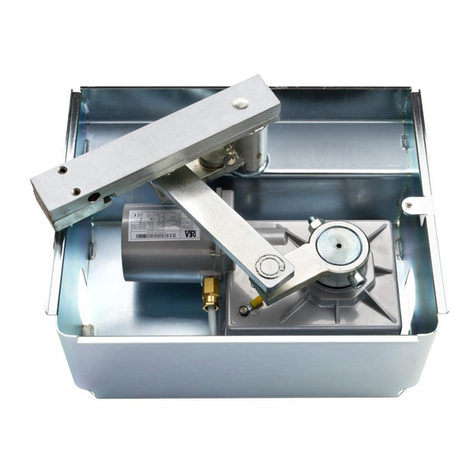
Dea Ghost 100 Series Product manual

I6212XX Rev. 03 21-11-16
Operatore elettromeccanico interrato per cancelli ad anta
Istruzioni d’uso ed avvertenze
Underground electro-mechanical operator for swing gates
Operating instructions and warnings
Motoréducteur électromécanique pour portails battants
Notice d’emploi et avertissements
Elektromechanischer Unterurantrieb für Drehtore
Bedienungsanleitung und Hinweise
Operador electromecánico para puertas con hoja batiente
Instrucciones de uso y advertencias
Operador electromecânico para portões de folha batente
Instruções para utilização e advertências
Siłownik elektromechaniczny do bram skrzydłowych
Instrukcja montażu i użytkowania
Подземный привод для распашных ворот
Инструкции и предупреждения

La Dichiarazione di Incorporazione può essere consultata sul sito
The Declaration of Incorporation may be consulted by entering
La Déclaration d’Incorporation peut être vérifié à l’adresse
Die Einbauerklärung kann abgerufen werden auf der Homepage
La Declaracion de Incorporación puede ser consultada en la dirección de internet
A Declaração de Incorporação pode ser consultada em
Deklarację Zgodności można skonsul tować wchodząc na st ronę
Декларация о регистрации можно ознакомиться, введя
http://www.deasystem.com
Nome ed indirizzo della persona autorizzata a costituire la
Documentazione Tecnica pertinente:
DEA SYSTEM S.p.A.
Via Della Tecnica, 6
36013 PIOVENE ROCCHETTE (VI) - ITALY
LIEVORE TIZIANO
Amministratore

5
GHOST
100
Underground electro-mechanical opera -
tor for swing gates
Operating instructions and warnings
Index
1Warnings Summary 56Start-up 7
2Product Description 6 6.1 Installation Test 7
3Technical data 6 6.2 Unlocking and manual operation 7
4Installation and Assembly 67Maintenance 8
5Electrical Connections 78Product Disposal 8
Product Conformity
DEA System guarantees the conformity of the product to European Directives 2006/42/CE regarding “machinery safety”, 2014/30/
EU “electromagnetic compatibility” and 2014/35/EU “low voltage electrical equipment”. See Declaration of Incorporation.
1 WARNINGS SUMMARY
Read these warnings carefully; failure to respect the following warnings may cause risk situations.
WARNING
using t h i s product under unusuaL conditions n ot foreseen b y t h e manufacturer c a n create situations o f d a n
-
ger, a n d f o r t h i s reason a L L t h e conditions prescribed i n these instructions m u s t b e respected.
WARNING DEA
sy s t e m reminds a L L users t h at t h e seLection, positioning a n d i n s ta L L at i o n o f a L L m a
-
teriaLs a n d devices Which m a k e u p t h e compLete automation sy s t e m , m u s t c o m p Ly With t h e european direc
-
tives 2006/42/ce (ma c h i n e r y directive), 2014/30/eu (eLectromagnetic compatibiLity), 2014/35/eu
(L o W vo L ta g e eLectricaL equipment). in order t o ensure a s u i ta b L e L e v e L o f s a f e t y , besides compLying With Lo
-
c a L reguLations, i t i s a d v i s a b L e to c o m p Ly a L s o With t h e a b o v e mentioned directives i n a L L extra european countries.
WARNING
under n o circumstances m u s t t h e product b e used i n expLosive atmospheres o r surroundings t h at m ay p r o v e
corrosive a n d d a m ag e p a r t s o f t h e product.
WARNING
to ensure a n appropriate L e v e L o f eLectricaL s a f e t y a LW ay s keep t h e 230v poWer s u p p Ly c a b L e s a p a r t (minimum
4m m i n t h e open o r 1 m m through insuLation) f r o m L oW v o Lt ag e c a b L e s (m o to r s poWer s u p p Ly , controLs, eLectric Locks, a e r i a L
a n d auxiLiary circuits poWer s u p p Ly ), a n d fa s t e n t h e L at t e r With appropriate c L a m p s n e a r t h e terminaL b o a r d s
.
WARNING
aL L i n s ta L L at i o n , maintenance, c L e a n i n g o r r e pa i r operations o n a n y p a r t o f t h e sy s t e m m u st b e performed
excLusiveLy b y quaLified personneL With t h e poWer s u p p Ly disconnected Working i n strict compLiance With t h e eLectricaL
s ta n d a r d s a n d reguLations i n f o r c e i n t h e nation o f i n s ta L L at i o n .
WARNING
using s pa r e p a r t s n o t indicated b y
DEA
sy s t e m a n d /o r incorrect r e -a s s e m b Ly c a n create risk t o p e o p L e , a n i
-
m a L s a n d p r o p e r t y a n d a L s o d a m a g e t h e product. fo r t h i s reason, a L W ay s use o n Ly t h e p a r t s indicated b y
DEA
sy s t e m a n d
s c r u p u L o u s Ly f o L L o W a L L a s s e m b Ly instructions.
WARNING
incorrect assessment o f t h e i m p ac t f o r c e s c a n cause serious da m a g e t o p e o p L e , a n i m a L s o r things.
DEA
sy s
-
tem reminds t h e i n s ta L L e r m u s t verify t h at t h e i m p ac t f o r c e s , measured a s indicated b y t h e s ta n d a r d en 12445, a r e ac t u a L Ly
b e L o W t h e Limits set by t h e s ta n d a r d en12453.
WARNING
an y externaL security devices used f o r compLiance With t h e Limits o f i m p ac t f o r c e s m u st b e conform t o s ta n d
-
a r d en12978
.
WARNING
in compLiance With eu directive 2012/19/eu o n Wa s t e eLectricaL a n d eLectronic equipment (Weee), t h i s
eLectricaL product s h o u L d n ot b e treated a s municipaL mixed W a s t e . pL e a s e dispose o f t h e product a n d bring i t t o t h e
coLLection f o r a n appropriate L o c a L municipaL recycLing
.

6
2 PRODUCT DESCRIPTION
Models and contents of the package
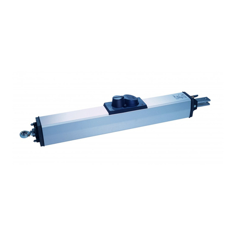
The name GHOST 100 identies a series of underground electro-mechanical operators for the automation of swing gates with diffe-
rent features depending on motor phase power supply and the presence of the encoder.
GHOST 100 is completed by a set of accessories listed in the “PRODUCT ACCESSORIES” table (page 38).
GHOST 100 is an electromechanical operator for swing gates rotating an articulated arm. This arm is connected to the gate to be
operated by means of the lever unit of the foundation box. The lever unit, that will be properly welded at the time of installation, has a
built-in operator unlocking device which will allow you to open the gate even if there is a power supply failure.
Inspect the “Contents of the Package” (Pic. 1) and compare it with your product for useful consultation during assembly.
Transport
GHOST 100 is always delivered packed in boxes that provide adequate protection to the product, however, pay attention to all infor-
mation that may be provided on the same box for storage and handling.
3 TECHNICAL DATA
100 - 100/CL - 100EN/CL 100/EN 100/24 - 100/24CL
Motor power supply voltage (V) 230 V ~ ±10% (50/60 Hz) 24 V
Absorbed power (W) 250 50
Max torque (Nm) 250 200
Duty cycle (cycles/hour) 18 25 40
Maximum n° of operations in 24 hour * 100 100
Built-in capacitor (µF) 10 -
Operating temperature range (°C) -20 ÷ 50 °C
Motor thermal protection (°C) 150 °C -
Opening time 90° (s) * 16 14
Maximum opening degree 110°
Weight of product with package (kg) 11
Protection degree IP67
* The data refer to the use in combination with NET series control boards and with parameters of speed and slowdown set as per default.
4 INSTALLATION AND ASSEMBLY
4.1 For a satisfactory installation of the product is important to:
• Verify that the structure complies with the regulations and then dene the complete design of the installation;
• Make sure the gate is well balanced and there aren’t points of friction while closing and opening;
• Identify an area that allows a smooth and safe manual operation of the operator;
• Ensure that the foundation box dimensions are conformable with the selected area for the assembly (Pic. 2);
• Provide a stop stroke in closing and possible also in opening;
• Use the lenght/weight diagram and installation dimensions provided (Pic. 4) for a correct positioning of the box with respect to the
door to be moved .
4.2 Once you have dened and satised these requirements, proceed with the assembly:
• Dig a hole suitable for the type of ground using the dimensions shown in Pic. 3 as a reference;
• Prepare an adequate number of channels for the passage of electric cables and drainage in order to avoid water build up;
WARNING All operator wirings must be run outside of the foundation box and inside proper watertight cases. To ensure the product
protection degree, the power supply cable of the operator must not be cut.
• Position the box inside the hole making sure that the pin is alligned with the axis of the hinge (Pic. 4);
• Start setting the concrete and, before it dries, make sure it is perfectly levelled;
Wait for the concrete completely dry;
• Insert the ball on the shaft provided on the box and then the release lever assembly;
Warning: properly lubricate the pivot point;
• Place the door of the gate on the release pin and x the two parts with a good weld;
• Place the operator inside the foundation box making sure that it is inserted in the right direction (Pic. 5);
• Secure the motor with the appropriate washers and nuts supplied;
• Connect the lever of the gearbox to the release mechanism, with the junction bracket;

7
4.3 How to unlock the operator
WARNING Disconnect the power supply from the control panel before releasing the operator. In case you cannot turn the power
off, you will necessarily have to re-lock the motor in the position in which it was unlocked.
Use the manual release key to unlock the gate (Pic. 6), the operator is unlocked and the gate can move freely. To lock the gate, bring
the gate on the lever assembly which will lock the spring device and brings GHOST 100 in working condition.
4.4 How to x and adjust the mechanical stops
All GHOST 100 models are supplied with mechanical stops that permit the stroke adjustment while closing and opening when xed
stops are xed.
For the assembly and adjustment, proceed as it follows:
• Unlock the operator;
• Position the door approximately to 45° so as to facilitate the assembly;
• Mount the mechanical stops as shown in Pic. 7;
• Adjust the screws (A) and manually move the leaf verifying the correct positioning of the stroke;
• After completing the adjustment, tighten the locking nut (B)
WARNING Mechanical stops must be used with doors up to 200kg for models without encoder and up to 300kg for models with
encoder.
5 ELECTRICAL CONNECTIONS
WARNING To ensure an appropriate level of electrical safety always keep the 230V power supply cables apart (minimum 4mm in the
open or 1 mm through insulation) from low voltage cables (motors power supply, controls, electric locks, aerial and auxiliary circuits
power supply), and fasten the latter with appropriate clamps near the terminal boards.
WARNING During the connection phase, fasten the electric cables with appropriate clamps near the terminal boards and, when possible,
unsheathe the cables to avoid they are too long.
WARNING Maintain the ground conductor at a major length respect the active conductors so that, if the cable exit from its xing housing,
the active conductors tighten up as rst.
Program the control board to complete all adjustments. It is now possible to supply a complete installation in compliance with all stan-
dards required for gate automation. See the instructions provided with the control panel to be connected.
Finally, verify that all adjustments operations have been correctly performed and that safety devices and unlocking device properly
work.
6 START-UP
The start-up phase is very important to ensure maximum security and compliance to regulations, including all the requirements of EN
12445 standard which establishes the test methods for testing the automation for gates.
DEA System reminds that all installation, maintenance, cleaning or repair operations on any part of the system must be performed
exclusively by qualied personnel who must be responsible of all texts requie by the eventual risk;
6.1 Installation test
The testing operation is essential in order to verify the correct installation of the system. DEA System wants to summarize the proper
testing of all the automation in 4 easy steps:
• Make sure that you comply strictly as described in paragraph 2 “WARNINGS SUMMARY”;
• Test the opening and closing making sure that the movement of the leaf match as expected.
We suggest in this regard to perform various tests to assess the smoothness of the gate and defects in assembly or adjustment ;
• Ensure that all safety devices connected work properly ;
• Perform the measurement of impact forces in accordance with the standard 12445 to nd the setting that ensures compliance with
the limits set by the standard EN12453 .
WARNING Using spare parts not indicated by DEA System and/or incorrect re-assembly can create a risk to people, animals and
property and also damage the product. For this reason, always use only the parts indicated by DEA System and scrupulously follow all
assembly instructions.
6.2 Unlocking and Manual operation
In the event of malfunctions or simple power failure, release the motor (Pic. 6) and perform the operation manually.
The knowledge of the unlocking device is very important because, in times of emergency, lack of speed in operating this device can
cause danger.
WARNING The efcancy and safety of manual operation of the automation is guaranteed by DEA System only if the installation has
been installed correctly and with original accessories.

8
7 MAINTENANCE
Good preventive maintenance and regular inspection ensure
long working life. In the table below you will nd a listo f inspections/
maintenance operations to be programmed and executed periodi-
cally.
Consult the TROUBLE-SHOOTING” table whenever anomalies are
observed in order to nd the solution to the problem and contact
DEA System directly whenever the solution required is not provided.
INTERVENTION TYPE PERIODICITY
cleaning of external surfaces 6 months
checking of screw tightening 6 months
checking of release mechanism operation 6 months
check that water ows out properly from
the foundation box 6 months
greasing of articulated joint 1 year
TROUBLE-SHOOTING
Description Possible solutions
When the opening command is given, the gate wing fails to
move and the operator’s electric motor fails to start.
The operator is not receiving correct power supply. Check all connections, fuses, and the
power supply cable conditions and replace or repair it if necessary. If the gate does not close
check if the photocells work properly.
When the opening command is given, the motor starts but
the gate leaf fails to move.
Make sure the unlocking system is closed.
Make sure that the electronic device for power adjustment is in good condition.
The operator jerks or is noisy during movement, it stops
midway or else it does not start.
If the leaf of the gate does not move freely, release the operator and readjust the rotation
points.
The power of the gearmotor may be insufcient for the characteristics of the gate’s leaf;
check the choice of model whenever required.
Make sure that the electronic device for power adjustment is in good condition.
8 PRODUCT DISPOSAL
GHOST 100 consists of materials of various types, some of which can be recycled (electrical cables, plastic, aluminum, etc. ..) while
others must be disposed of (electronic boards and components).
Proceed as follows:
1. Disconnect the power supply;
2. Disconnect and disassemble all the accessories connected. Follow the instructions in reverse to that described in the section “Installa-
tion”;
3. Remove the electronic components;
4. Sorting and disposing of the materials exactly as per the regulations in the country of sale.
WARNING In line with EU Directive 2012/19/EU for waste electrical and electronic equipment (WEEE), this electrical product must
not be disposed of as unsorted municipal waste. Please dispose of this product by returning it to your local municipal collection
point for recycling.

33
Esempio di installazion tipica - Example of typical installation - Exemple d’installation typique - Installationsbeispiel - Ejemplo de insta-
lación típica - Exemplo de instalação típica - Przyład standardowego systemu automatyzacji - Пример типового монтажа
Pos. Descrizione - Description - Description - Beschreibung - Descripción - Descrição - Opis - Описание
1 GHOST 100
2 Fotocellule - Photocells - Photocellules - Lichtschranke - Fotocélulas - Fotocélulas - Fotokomórki - фотоэлементы
3 Safety edge - Bord sensible - Sichereitsleiste - Borde sensible - Dispositivo sensível de protecção - Listwa bezpieczeństwa - Ребро безопасности
4 Lampeggiante - Flashing light - Clignotant - Blinkleuchte - Lámpara - Intermitente - Lampa Ostrzegawcza - Сигнальная лампа
5Selettore a chiave antiscasso - Anti lock-picking key switch - Sélecteur à clé anti-intrusion - Einbruchfester Schlüsselschalter - Selector a llave antisabotaje
- Interruptor de chave burglar - Przełącznik kluczowy wandaloodporny - Замковый выключатель
6 Radiocomando - Remote-control - Radiocommande - Handsender - Radiocomando - Comando via rádio - Nadajnik - Пульт ДУ
7 Selettore digitale - Radio keypad - Digicode radio - Funkcodie - Teclado digital radio - Teclado via radio - Bezprzewodowa klawiatura - Радио кодовая панель
4x1 mm² (230V) o 3x1,5 mm² (24V)4x1 mm² (230V) o 3x1,5 mm² (24V)
B
B
4x0,5 mm²
2x0,5 mm²
3x0,5 mm²
2 x 0,5 mm² (RG58)
2x0,5 mm²
2x0,5 mm² 4x0,5 mm²
Collegarsi alla rete 230 V ± 10% 50-60 Hz tramite un interruttore onnipolare o altro dispositivo che assicuri la onnipolare disinserzione della rete, con una
distanza di apertura dei contatti ≥ 3 mm - Make the 230V ± 10% 50-60 Hz mains connection using an omnipolar switch or any other device that guaran-
tees the omnipolar disconnection of the mains network with a contact opening distance of 3 mm - Connectez-vous au réseau 230 V ± 10% 50-60 Hz au
moyen d’un interrupteur omnipolaire ou d’un autre dispositif qui assure le débranchement omnipolaire du réseau, avec un écartement des contacts égal à
3 mm. - Den Anschluss an das 230 V ~ ± 10% 50-60 Hz Netz mit einem Allpolschalter oder einer anderen Vorrichtung vornehmen, durch die eine allpolige
Netzunterbrechung bei einem Öffnungsabstand der Kontakte von ≥ 3 mm gewährleistet wird. - Efectuar la conexión a una línea eléctrica 230 V ± 10%
50-60 Hz a través de un interruptor omnipolar u otro dispositivo que asegure la omnipolar desconexión de la línea, con 3 mm de distancia de abertura de
los contactos. - Ligue na rede de 230 V. ± 10% 50-60 Hz mediante um interruptor omnipolar ou outro dispositivo que assegure que se desliga de maneira
omnipolar da rede, com abertura dos contactos de pelo menos 3 mm. de distância - Podłączyć się do sieci 230 V ± 10% 50-60 Hz poprzez przełącznik
jednobiegunowy lub inne urządzenie które zapewni brak zakłóceń w sieci, przy odległości między stykami ≥ 3 mm. - Подключайтесь к сети 230V ± 10%
50-60 Гц с помощью многополюсного выключателя или используйте любое другое устройство, которое гарантирует многополюсное отключение
питающей сети с расстоянием между контактами от ≥ 3 мм и больше.
Collegare a terra tutte le masse metalliche - All metal parts must be grounded - Connectez toutes les masses métalliques à la terre - Alle Metallteile erden
- Conectar con la tierra todas las masas metálicas - Realize ligação à terra de todas as massas metálicas - Uziemić wszystkie elementy metalowe. - Все
металлические части должны быть заземлены.
DEA System fornisce queste indicazioni che si possono ritenere valide per un im-
pianto tipo ma che non possono essere complete. Per ogni automatismo, infatti,
l’installatore deve valutare attentamente le reali condizioni del posto ed i requisiti
dell’installazione in termini di prestazioni e di sicurezza; sarà in base a queste
considerazioni che redigerà l’analisi dei rischi e progetterà nel dettaglio l’auto-
matismo. - DEA System provides the following instructions which are valid for a
typical system but obviously not complete for every system. For each automatism
the installer must carefully evaluate the real conditions existing at the site. The
installation requisites in terms of both performance and safety must be based
upon such considerations, which will also form the basis for the risk analysis and
the detailed design of the automatism. - DEA System fournit ces indications que
vous pouvez considérer comme valables pour une installation-type, même si elles
ne peuvent pas être complètes. En effet, pour chaque automatisation, l’installa-
teur doit évaluer attentivement les conditions réelles du site et les pré-requis de
l’installation au point de vue performances et sécurité ; c’est sur la base de ces
considérations qu’il rédigera l’analyse des risques et qu’il concevra l’automatisa-
tion d’une manière détaillée. - Diese Angaben von DEA System können als gül-
tig für eine Standardanlage angesehen werden, können aber nicht erschöpfend
sein. So muss der Installationsfachmann für jedes Automatiksystem sorgfältig die
Voraussetzungen des Installationsortes sowie die Leistungs- und Sicherheitsan-
forderungen an die Installation abwägen; aufgrund dieser Überlegungen muss er
die Risikobewertung erstellen und genau das Automatiksystem entwickeln. - DEA
System facilita estas indicaciones que pueden considerarse válidas para una
instalación tipo pero que no pueden considerarse completas. El instalador, en
efecto, tiene que evaluar atentamente para cada automatismo las reales condi-
ciones del sitio y los requisitos de la instalación por lo que se reere a presta-
ciones y seguridad; en función de estas consideraciones redactará el análisis de
riesgos y efectuará el proyecto detallado del automatismo. - DEA System fornece
estas indicações que podem ser consideradas válidas para o equipamento pa-
drão, mas que podem não ser completas. Para cada automatismo praticamente
o técnico de instalação deverá avaliar com atenção as condições reais do sítio
e os requisitos da instalação em termos de performance e de segurança; será
em função destas considerações que realizará uma análise dos riscos e projec-
tará. - DEA System dostarcza wskazówek, do wykorzystania w typowej instalacji
ale nie będą one nigdy kompletne. Dla każdego typu automatyki, instalator musi
sam oszacować realne warunki miejsca montażu i wymogi instalacyjne mając na
uwadze przepisy dotyczące bezpieczeństwa. Na podstawie zebranych informacji
będzie w stanie przeanalizować zagrożenia mogące wystąpić i zaprojektować w
szczegółach automatyzację. - DEA System предлагает рекомендации , которые
действительны для типовой системы , но , очевидно, не обязательны для каждой
конкретной установки. Для каждого конкретного случая установщик должен
тщательно оценить реальные условия. Устройства для установки оцениваются
с точки зрения производительности и безопасности, которые необходимы для
анализа рисков и детального проектирования системы автоматизации.

34
4
1
2
2
4
4
4
150150
423
173 50,5
200
253,5 80,5
103 70
70
750
500
350

35
ATTENZIONE Tutti i cablaggi dell’operatore devono essere
effettuati all’esterno della cassa di fondazione ed all’interno di appositi
contenitori a tenuta stagna.
WARNING All operator wirings must be performed outside the
foundation box and inside proper watertight cases.
ATTENTION Tous les cablâges de l’opérateur doivent être
efféctués en dehors de la caisse de fondation et dans des conteneurs
étanches.
ACHTUNG Allfällige Elektroanschlüsse müssen außerhalb des
Fundamentkastens und in entsprechenden dichten Abzweigdosen
verkabelt werden.
ATENCIÓN Todos los cableados del operador deben estar
efectuados en el externo de la caja de cimentación y en el interior de
una caja de conexiones estanca.
ATENÇÃO Todas as ligações do motor devem ser executadas fora
da caixa de fundação e dentro de caixas estanques.
UWAGA Całe okablowanie siłownika powinno zostać wykonane na
zewnątrz skrzynki fundamentowej oraz zabezpieczone rurami
izolacyjnymi oraz puszkami hermetycznymi.
ВНИМАНИЕ Вся кабельная проводка устройства должна
выполняться за пределами фундаментного ящика и в
специальных водонепроницаемых контейнерах.
70
Struttura fissa, Fixed structure,
Structure fixe, Wand,
Estructura fija, Estrutura fixa,
Stała struktura, Неподвижная
структура
Scatola di derivazione, Shunt box,
Boîte de dérivation, Verteilerdose,
Caja de derivación, Caixa de
derivações, Skrzynka przyłączeniowa,
Распределительная коробка
Anta cancello,
Door gate, Leaf,
Schiebetor,
Hoja, Folha,
Brama,
Створка ворот
Pozzetto in cemento,
Concrete shaft, Envelop-
pe de béton,
Betonschacht, Fuste de
hormigón, Eixo de
concreto, Wał betonowy,
Цементный люк
Cavi, Cables, Câbles,
Verdrahtung, Cables, Cabos,
Kable, Кабели
Tubo di scarico acqua, Drainpi-
pe, Tuyau de sortie de l’eau,
Drenage, Tubo de desagüe,
Tubo de descarga d’água, Rura
odpływowa, Шланг слива воды
ATTENZIONE Se la lunghezza dell’anta è maggiore ai 2 mt, è necessario installare
l'elettroserratura per il blocco del cancello in posizione di chiusura.
ATTENZIONE L’altezza e la struttura dell’anta, così come la presenza di vento forte,
possono causare la riduzione del valore dei dati riportati in tabella.
ATTENZIONE I dati indicati sono tutti riferiti con rallentamenti attivi.
WARNING In case the leaf length is more than 2 mt, it is necessary to install the electric
lock to hold the gate in closing position.
WARNING Leaf height and structure as well as strongwinds may reduce data figures given
in the table.
WARNING The data provided are valid when slowdowns are enabled.
ATTENTION Si la longueur du vantail est plus grande de 2 mt., il faut installer
l’électro-serrure pour bloquer le portail en position de fermeture.
ATTENTION La hauteur et la structure du vantail, aussi bien que le vent fort peuvent
réduire la valeur des données indiquées sur la table.
ATTENTION Les données indiquées sont valables quand les ralentissements sont actifs.
ACHTUNG Sollte die Flügellänge 2 m übersteigen, muss ein Elektroschloss zur Blockie-
rung des geschlossenen Tors installiert werden.
ACHTUNG Flügelhöhe, -struktur ebenso wie starker Wind können Ursache für geringere
Tabellenwerte sein.
ACHTUNG Die angegebenen Daten beziehen sich auf Antriebe mit aktivierter Verlangsa-
mung
ATENCIÓN Si la longitud de la hoja es mayor a los 2 mts., es necesario instalar la
electrocerradura para el bloqueo de la hoja en posición de cierre.
ATENCIÓN La altura y la estructura de la puerta, así como la presencia de viento fuerte,
pueden provocar la reducción del valor de los datos indicados en la tabla.
ATENCIÓN Los datos indicados se refieren a una instalación con desaceleración
activada.
ATENÇÃO Se o comprimento da folha for superior a 2 mt, é necessário instalar uma fechadura eléctrica para o bloqueio da porta na posição de fechada.
ATENÇÃO A altura e a estrutura da folha, como a presença de vento forte, podem causar a redução dos dados indicados na tabela.
ATENÇÃO Os dados indicados referem-se a uma instalação com o abrandamento activado.
UWAGA Jeśli długość skrzydła bramy przekracza 2 mt, należy zamontować elektrozamek.
UWAGA Wysokość i struktura skrzydła bramy, podobnie jak występowanie zbyt silnego wiatru, mogą wpływać na wybór mniejszych wartości danych podanych w tabeli.
UWAGA Wymienione funkcje, w całości, są aktywne przy włączonym spowolnieniu.
ВНИМАНИЕ Если длина створки превышает 2 метра, необходимо установить электрический замок для блокирования ворот в закрытом положении.
ВНИМАНИЕ Высота структуры створки, также как и сильный ветер, могут привести к снижению величин данных, указанных в таблице.
ВНИМАНИЕ Представленные данные действительны при включенном замедлений.
100 - 100/CL
100/EN
100EN/CL
CON BATTUTE FISSE A TERRA, WITH STOPS FIXED TO
THE GROUND, AVEC BUTÉES FIXES AU SOL, MIT
FESTSTEHENDEN BODENANSCHLÄGEN, CON TOPES
FIJOS EN EL SUELO, COM ELEMENTOS FIXOS NO SOLO,
PRZYMOCOWANE DO PODŁOŻA, С НЕПОДВИЖНЫМ
УПОРОМ НА ЗЕМЛЕ
CON FERMI ART. 118, WITH ART. 118 STOPS,
AVEC ARRÊTS ART. 118, MIT SPERREN LT.
ART. 118, CON TOPES ART. 118,
CONFORME ART. 118, Z ZACISKAMI ART. 118,
СО СТОПОРАМИ АРТ. 118
100/24 - 100/24CL
CON BATTUTE FISSE A TERRA, WITH STOPS FIXED TO
THE GROUND, AVEC BUTÉES FIXES AU SOL, MIT
FESTSTEHENDEN BODENANSCHLÄGEN, CON TOPES
FIJOS EN EL SUELO, COM ELEMENTOS FIXOS NO SOLO,
PRZYMOCOWANE DO PODŁOŻA, С НЕПОДВИЖНЫМ
УПОРОМ НА ЗЕМЛЕ
CON FERMI ART. 118, WITH ART. 118 STOPS,
AVEC ARRÊTS ART. 118, MIT SPERREN LT.
ART. 118, CON TOPES ART. 118,
CONFORME ART. 118, Z ZACISKAMI ART. 118,
СО СТОПОРАМИ АРТ. 118

36
In fase di posizionamento del motoriduttore sulla cassa, la calotta marchiata DEA va rivolta sempre verso la direzione di apertura.
When positioning the operator on the foundation box, the cap marked DEA should always facing the opening direction.
Lors du positionnement du moteur sur la boîte de fondation, le couvercle marqué DEA doit toujours facer la direction d’ouverture.
Bei Platzierung des Antriebes muss der Aufdruck DEA auf dem Getriebegehäuse von DEA immer in Öffnungsrichtung ausgerichtet werden.
Al colocar el motor en la caja de cimentación, la tapa del motor marcada DEA debe siempre estar orientada en la dirección de apertura.
Quando montar o motor na caixa de fundação, a tampa da bobinagem do motor com a etiqueta DEA deve ficar sempre voltada para a direção da abertura.
Podczas wkładania motoreduktra do skrzyni, nakładka osłony z oznaczeniem DEA zawsze powinna być ustawiona w kierunku otwarcia.
В фазе позиционирования мотор-редуктора в ящик, крышка с маркировкой DEA всегда поворачивается по направлению открытия.
B
A
ATTENZIONE I fermi meccanici devono essere utilizzati con ante fino a 200Kg per modelli senza encoder e fino a 300Kg per modelli con encoder.
WARNING Mechanical stops must be used with doors up to 200kg for models without encoder and up to 300kg for models with encoder.
ATTENTION Les fins de course mécaniques doivent être utilisées avec vantaux jusqu’à 200Kg pour modèles sans encodeur et jusqu’à 300Kg pour modèles avec encodeur.
ACHTUNG Diese mechanische Anschläge dürfen für Torflügeln bis 200 kg bei Antriebe ohne Encoder und bis 300 kg bei Antriebe mit Encoder eingesetzt werden.
ATENCIÓN los topes mecánicos se deben utilizar con puertas de hasta 200 kg para los modelos sin encoder y hasta 300 kg para los modelos con encoder.
AVISO Devem ser utilizados fins de curso mecânicos para portas até 200Kg para modelos sem encoder e até 300 Kg para modelos com encoder
UWAGA Ograniczniki mechaniczne są przeznaczone do montażu skrzydeł do 200kg – dla modeli bez encodera, oraz dla skrzydeł do 300kg - dla modeli z encoderem.
ПРЕДУПРЕЖДЕНИЕ механические ограничители должны быть использованы с дверей до 200кг для моделей без датчика и до 300 кг для моделей с датчиком.

37
Esploso di assemplaggio, Assembly diagram, Schéma de montage, Explosionszeichnung für den Zusammenbau
Esquema de montaje, Esquema de montagem, Części zamienne, Сборочный чертеж
x4

38
Tabella “ACCESSORI PRODOTTO”, Table “PRODUCT ACCESSORIES”, Tableau “ACCESSOIRES PRODUITS”, Tabelle „PRODUKTZUBE-
HÖR”, Tabla “ACCESORIOS PRODUCTO”, Tabela “ACESSÓRIOS DO PRODUTO”, Tabell “AKCESORIA DODATKOWE”,
Таблица “АКСЕССУАРЫ ИЗДЕЛИЯ”.
Article
Code
Descrizione, Description, Description,
Beschreibung, Descripción, Descrição, Opis, Описание
115
629003
Cassa di fondazione in cataforesi con meccanismo di sblocco
Foundation box with cataphoresis treatment with unlocking device
Caisse de fondation en cataphorese avec dispositif de déverrouillage
Fundamentkasten mit Kataphorese Beschichtung und Entriegelungsmechanik
Caja de cimentación con cataforesis con mecanismo de desbloqueo
Caixa de fundação em cataforese com dispositivo de desbloqueio
Skrzynia fundamentowa w powłoce kataforezowej z zawiasem z mechanizmem
odblokowania
Фундаментный ящик из катафореза с механизмом разблокирования
115i
629013
Cassa di fondazione in inox con meccanismo di sblocco
Stainless steel foundation box with unlocking device
Caisse de fondation inox avec dispositif de déverrouillage
Fundamentkasten in Edelstahl mit Entriegelungsmechanik
Caja de cimentación en inox con mecanismo de desbloqueo
Caixa de fundação em inox com dispositivo de desbloqueio
Skrzynia fundamentowa ze stali nierdzewnej z zawiasem z mechanizmem odbl-
kowania
Фундаментный ящик из нержавеющей стали с механизмом разблокирования
116G
629021
Accessorio per apertura no a 180°
Device to get an opening angle up to 180°
Accessoire pour ouverture jusqu’à 180°
Zubehör für Öffnungswinkel bis 180°
Accesorio para abertura hasta 180°
Dispositivo para obter um ângulo de abertura de até 180°
Zawias do otwierania o kąt 180°
Комплектующее для открытия на 180°
118
629031
Finecorsa meccanici
Mechanical limit switches
Fins de course mécaniques
Mechanische Endanschläge
Final de carrera mecánico
Fins de curso mecânicos
Mechaniczny ogranicznik krańcowy
Механические концевые выключатели

INSTRUCTIONS FOR THE FINAL USER
This guide has been prepared for the nal users of the automatism; the installer is required to deliver this gui-
de and illustrate its contents to the person in charge of the system. The latter must then provide similar instruc-
tion to all the other users. These instructions must be carefully conserved and easily available for consultation
when required.
Good preventive maintenance and frequent inspection ensures the long working life of the product. Contact
the installer regularly for routine maintenance and in event of anomaly.
SAFETY RULES
1. Always keep a safe distance from the automatism during operation and never touch any moving part.
2. Prevent children from playing near the automatism.
3. Perform the control and inspection operations prescribed in the maintenance schedule and immediately stop
using the automatism whenever signs of malfunction are noted.
4. Never disassemble parts of the product! All maintenance and repair operations must be performed only by
qualied personnel.
5. The release operation must sometimes be performed in emergencies! All users must be instructed on the use
of the release mechanism and the location of the release keys.
GHOST 100 RELEASE MECHANISM
WARNING Disconnect the power supply from the control panel before releasing the operator. In case you
cannot turn the power off, you will necessarily have to re-lock the motor in the position in which it was
unlocked.
All GHOST 100 models are equipped with a release device which must be operated as follows:
1. Disconnect the power supply;
2. Use the manual release key to unlock the gate (Pic. 6), the operator is unlocked and the gate can move freely.
To lock the gate, bring the gate on the lever assembly which will lock the spring device and brings GHOST 100
in working condition.
WARNING: During this operation gate may present uncontrolled movement: operate with extra care so to
avoid any risk.
CLEANING AND INSPECTIONS
The only operation that the user can and must do is to remove branches, leaves, and any other object that
might obstruct the gate’s free movement. Warning! Always disconnect the power supply whenever performing
operations on the gate!
DEA SYSTEM S.p.A. - Via Della Tecnica, 6 - ITALY - 36013 PIOVENE ROCCHETTE (VI)
tel. +39 0445 550789 - fax +39 0445 550265 - Internet http:\\www.deasystem.com - e-mail: deasystem@deasystem.com


DEA SYSTEM S.p.A.
Via Della Tecnica, 6
36013 PIOVENE ROCCHETTE (VI) - ITALY
tel. +39 0445 550789 - fax +39 0445 550265
Internet http:\\www.deasystem.com - e-mail: [email protected]
Other manuals for Ghost 100 Series
1
This manual suits for next models
5
Table of contents
Other Dea Gate Opener manuals