FAAC B680H User manual

B680H
Read this instruction manual to the letter before you begin to install the product.
Symbol highlights notes that are important for people’s safety and for the good condition of the automated system.
Symbol draws your attention to the notes about the product’s characteristics or operation
www.FastGateOpeners.com | (800) 878-7829 | [email protected]

1
ENGLISH
INDEX
B680H AUTOMATED SYSTEM
1. TECHNICAL SPECIFICATIONS ............................................................................................................................................................3
1.1 Summary table...............................................................................................................................................................................3
1.2 Key Fig. 5........................................................................................................................................................................................3
1.3 Key Fig. 6........................................................................................................................................................................................3
2. ELECTRICAL PREPARATIONS (standard system) ............................................................................................................................3
3. BARRIER DIMENSIONS........................................................................................................................................................................3
4. INSTALLING THE AUTOMATED SYSTEM ...........................................................................................................................................3
4.1 Preliminary checks .......................................................................................................................................................................3
4.2 Walling in the foundation plate ...................................................................................................................................................3
4.3 Electrical preparations.................................................................................................................................................................3
4.4 Mechanical installation ................................................................................................................................................................3
4.5 Fixing the plunging pistons.........................................................................................................................................................4
4.6 Balancing the barrier....................................................................................................................................................................4
5. START-UP...............................................................................................................................................................................................4
5.1 Connecting the control equipment .............................................................................................................................................4
5.2 Testing the automated system ....................................................................................................................................................4
6. MANUAL OPERATION ..........................................................................................................................................................................4
7. RESTORING NORMAL OPERATION....................................................................................................................................................4
8. MAINTENANCE .....................................................................................................................................................................................4
8.1 Topping up the oil .........................................................................................................................................................................4
8.2 Air bleeding ...................................................................................................................................................................................4
9. REVERSING THE OPENING DIRECTION ............................................................................................................................................4
10. ACCESSORIES....................................................................................................................................................................................5
10.1 Installing a photocell .................................................................................................................................................................5
10.2 Installing the bar light kit ...........................................................................................................................................................5
10.3 Installation of a receiver antenna..............................................................................................................................................5
11. REPAIRS...............................................................................................................................................................................................5
E680 CONTROL BOARD
1. WARNINGS ............................................................................................................................................................................................6
2. DESCRIPTION OF THE COMPONENTS ..............................................................................................................................................6
3. TECHNICAL SPECIFICATIONS ............................................................................................................................................................6
4. ELECTRICAL CONNECTIONS..............................................................................................................................................................7
4.1 Terminal board J1 (inputs) ...........................................................................................................................................................7
4.2 Terminal board J2 (outputs).........................................................................................................................................................8
4.3 Terminal board J3 (external ashing lamp) ...............................................................................................................................8
4.4 Terminal board J4 (loop detector) ..............................................................................................................................................8
4.5 Connector J5 (Motor)....................................................................................................................................................................8
4.6 Connector J7 (Encoder)...............................................................................................................................................................8
4.7 Connector J10 (Radio)..................................................................................................................................................................8
4.8 Connector J11 (Beam break-out sensor) ...................................................................................................................................8
4.9 Connector J12 (Emergency battery)...........................................................................................................................................8
4.10 Connector J13 (36VDC Power Supply) .....................................................................................................................................8
4.11 Connector J15 (ashing trafc light) ........................................................................................................................................8
5. PROGRAMMING....................................................................................................................................................................................8
5.1 Basic conguration.......................................................................................................................................................................9
5.2 Changing the predened parameters set ................................................................................................................................10
5.3 BUS accessories menu ..............................................................................................................................................................11
6. Advanced Conguration ....................................................................................................................................................................12
6.1 Conguring the loop detector ...................................................................................................................................................13
6.2 Expert Conguration..................................................................................................................................................................14
6.3 Pre-Dened Parameter Sets......................................................................................................................................................17
6.4 “Expert” default parameters.....................................................................................................................................................18
7. START-UP.............................................................................................................................................................................................18
7.1 Verifying the diagnostic LEDs ...................................................................................................................................................18
7.2 Setup.............................................................................................................................................................................................18
8. TESTING THE AUTOMATED SYSTEM...............................................................................................................................................18
9. MASTER/SLAVE CONFIGURATION ...................................................................................................................................................19
10. INTERLOCK CONNECTION..............................................................................................................................................................19
11. OPERATING LOGICS TABLE............................................................................................................................................................20
12. BALANCING TABLES .......................................................................................................................................................................23
13. DEFAULT SELECTION TABLES .......................................................................................................................................................24

2
ENGLISH
CE DECLARATION OF CONFORMITY FOR MACHINES
(DIRECTIVE 2006/42/EC)
Manufacturer: FAAC S.p.A.
Address: Via Calari 10 - 40069 Zola Predosa BOLOGNA - ITALY
Declares that: The operator mod. B680H with control board E680
• isbuilttobeintegratedintoamachineortobeassembledwithothermachinerytocreateamachineunder
the provisions of Directive 2006/42/EC;
• conformstotheessentialsafetyrequirementsofthefollowingEECdirectives:
2006/95/ECLowVoltageDirective
2004/108/ECElectromagneticCompatibilityDirective
and also declares that itisprohibitedtoputintoservicethemachineryuntilthemachineinwhichitwillbe
integratedorofwhichitwillbecomeacomponenthasbeenidentiedanddeclaredasconformingtothe
conditions of Directive Directive 2006/42/EC.
Bologna,1October2011
TheManagingDirector
A. Marcellan
WARNINGS FOR THE INSTALLER
GENERAL SAFETY OBLIGATIONS
1) ATTENTION! To ensure the safety of people, it is important that you
read all the following instructions. Incorrect installation or incorrect
use of the product could cause serious harm to people.
2) Carefullyreadtheinstructionsbeforebeginningtoinstalltheproduct..
3) Donotleavepackingmaterials(plastic,polystyrene,etc.)withinreachof
childrenassuchmaterialsarepotentialsourcesofdanger.
4) Storetheseinstructionsforfuturereference.
5) Thisproductwasdesignedandbuiltstrictlyfortheuseindicatedinthisdo-
cumentation.Anyotheruse,notexpresslyindicatedhere,couldcompromise
thegoodcondition/operationoftheproductand/orbeasourceofdanger.
6) FAACdeclinesallliabilitycausedbyimproperuseoruseotherthanthatfor
whichtheautomatedsystemwasintended.
7) Donotinstalltheequipmentinanexplosiveatmosphere:thepresenceof
inammablegasorfumesisaseriousdangertosafety.
8) ThemechanicalpartsmustconformtotheprovisionsofStandardsEN12604
andEN12605.Fornon-EUcountries,toobtainanadequatelevelofsafety,
theStandardsmentionedabovemustbeobserved,inadditiontonational
legalregulations..
9) FAACisnotresponsibleforfailuretoobserveGoodTechniqueinthecon-
structionoftheclosingelementstobemotorised,orforanydeformationthat
mayoccurduringuse.
10) TheinstallationmustconformtoStandardsEN12453andEN12445.For
non-EUcountries,toobtainanadequatelevelofsafety,theStandardsmen-
tionedabovemustbeobserved,inadditiontonationallegalregulations..
11) Beforeattemptinganyworkonthesystem,cutoutelectricalpower.
12) Themainspowersupplyoftheautomatedsystemmustbettedwithan
all-poleswitchwithcontactopeningdistanceof3mmorgreater.Useofa
6Athermalbreakerwithall-polecircuitbreakisrecommended.
13) Makesurethatadifferentialswitchwiththresholdof0.03Aisttedupstream
ofthesystem.
14) Makesurethattheearthingsystemisperfectlyconstructed,andconnect
metalpartsoftheclosingelementstoit.
15) Theautomatedsystemfeaturesabuilt-inanti-crushingsafetydeviceconsisting
ofatorquecontrol.Itishowevernecessarytocheckitstrippingthreshold,
as provided for in the Standards described in point 10.
16) Thesafetydevices(EN12978standard)protectanydangerareasagainst
mechanicalmovementRisks,suchascrushing,dragging,andshearing.
17) Foreachsystem,werecommendusingatleastonesignallight(e.g.:FAA-
CLEDorintegratedashingtrafclight)aswellasawarningsignsecurely
xedtothestructure,togetherwiththedevicesdescribedinpoint“16”.
18) FAACdeclinesallliabilityasconcernssafetyandefcientoperationofthe
automatedsystem,ifsystemcomponentsnotproducedbyFAACareused.
19) Formaintenance,strictlyuseoriginalpartsbyFAAC.
20) Donotinanywaymodifythecomponentsoftheautomatedsystem
21) Theinstallershallsupplyallinformationconcerningmanualoperationofthe
systemincaseofanemergency,andshallhandovertotheUsertheleaet
suppliedwiththeproduct.
22) Donotallowchildrenoradultstostayneartheproductwhileitisoperating.
23) Keepradiocontrolsorotherpulsegeneratorsawayfromchildren,toprevent
theautomatedsystemfrombeingactivatedinvoluntarily.
24) Transitingispermittedonlywhentheautomatedsystemisstationary.
25) TheUsermustnotattemptanykindofrepairordirectactionwhateverand
contactqualiedpersonnelonly.
26) Maintenance:checkatleastevery6monthstheefciencyofthesystem,
particularlytheefciencyofthesafetydevices(including,whereforeseen,
theoperatorthrustforce)andofthereleasedevices.
27) Anythingnotexpresslyspeciedintheseinstructionsisnotpermitted.

3
ENGLISH
B680H AUTOMATED SYSTEM
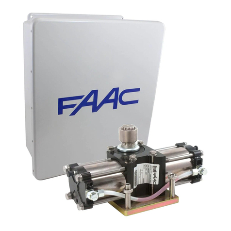
The automated system consists of a white aluminium beam with
reflectors,optionalsignallinglights,acoveringcompartmentandsteel
uprightprofile.Insidethecompartmentthereisanoperatorconsisting
oftheuprightprofilewithahydraulicunitandtwoplungingpistons
fixedtoit,which,bymeansofarockerarm,rotatethebeam.The
latterremainsbalancedthankstoabalancespringfittedononeofthe
twoplungingpistons.Theelectroniccontrolequipmentisalsohoused
ontheupright,insideacompartment,andthewholeisprotectedby
theexternalcoveringcompartment.
Thesystemfeaturesanadjustableelectronicanti-crushing safety,
a device that guarantees stopping and locking of the beam in
anyposition,andaconvenientmanual release for useincaseof
black-outorinefficiency.
1. TECHNICAL SPECIFICATIONS
1.1 Summary table
Power supply (V ~/ Hz) 90-240 V ~ / 50-60Hz
Electric Motor 36VdcBrushless
Absorbed power (W) 240
Absorbed current (A) 1,1Aat230V~
Motor rotation speed (RPM) 1000-6000
Pump capacity 3,2l/min(max)
Yielded torque (Nm) 0-370
Oil type FAAC HP OIL
Oil quantity (L) ~1,2
Anti-crushing System Electronicwithabsoluteencoder
Deceleration type Electronicwithabsoluteencoder
Operating ambient temperature (°C) -20 / +55
Rated Operating Time (ROT) ContinuousDutyat+55°C
Compartment protection treatment EP SL LF PRIMER
Beam type Roundedwithlightsandrubberbumper
Protection Class IP44
Compartment Dimensions
(LxHxP) (mm)
SeeillustrationFig.8
Weight (body + compartment) (kg) 65+20/85(total)
Opening and closing time (s),
including deceleration
1.5 - 2 m beam
6opening/9closing-8mbeam
a
Built-inashinglamp
b
Electroniccontrolequipment
c
Oilllingcap
d
Rightpistonbleederscrew
e
Hydraulicunit
f
Rightplungingpiston
g
Unitcoolingfan
h
Rightfeedtube
i
Leftfeedtube
j
Release lock
k
Leftplungingpiston
l
Left piston bleeder screw
m
Coveringcompartment
n
Encoder
o
Boxconnectingthemainpowersupply
p
Switchingpowersupply
a
Bearingstructure
b
Mechanical stops
c
Rocker arm
d
Drive shaft
e
Securingplate
f
Springguide
g
Balancespring
h
Preloadadjustmentringnut
1.2 Key Fig. 5
1.3 Key Fig. 6
2. ELECTRICAL PREPARATIONS (standard system)
SeedetailsintheillustrationFig.7.
3. BARRIER DIMENSIONS
All the dimensions contained in this manual are
expressed in mm
Forbarrierdimensions,refertoFig.8.Thecoveringcompartmentis
thesameforbothmodels,whilethebardimensionsdifferasshown
in detail at a(barS)andb(barL)-Fig.8
4. INSTALLING THE AUTOMATED SYSTEM
4.1 Preliminary checks
Forthesafetyandcorrectoperationoftheautomatedsystem,ensure
thatthefollowingconditionsaremet:
• Wheninmotion,thebeammustnotencounterobstaclesorying
power cables.
• Thecharacteristicsofthegroundmustguaranteesufcientsolidity
ofthefoundationplinth.
• No tubes or electrical cables should be present in the plinth
diggingarea.
• If the barrier body is exposed to vehicle transit, provide for
adequateprotectionagainstaccidentalimpact,whenpossible.
• Ensurethatthereisanefcientearthplateforconnectingthe
uprightprole.
Wall in the foundation plate so as to allow easy access to
the barrier door. The foundation plinth must be installed
keeping in mind the characteristics of the ground to
ensure perfect stability of the automated system.
4.2 Walling in the foundation plate
• AssemblethefoundationplateasshowninFig.9ref.a
•SetthefoundationplinthasshowninFig.9ref.b
•WallinthefoundationplateasshowninFig.9ref.bproviding
foroneormoresheathsforthepassageoftheelectricalcables.
For dimensional reasons, the cable passage sheaths
must be placed on one side of the space provided at
the base of the barrier (see Fig. 9).
•Usea level toensurethat the plateisperfectly horizontal.
Waitforthecementtoset.
4.3 Electrical preparations
Following the instructions shown in Fig. 7, prepare the ducts to
make all the control board electrical connections with the chosen
accessories.
Alwaysseparatethepowercablesfromthecontrolandsafetycables
(button,receiver,photocells,etc.).
Use the cable diameters shown in Fig. 7 and referred to in the
followingkey:
a
Barrier mod. B680H
b
Photocells
c
Keybutton
d
Flashinglamp
e
Radio receiver
f
MagneticLoops
4.4 Mechanical installation
• Fixtheuprightprofileontothefoundationplateusingthefour
providednuts(Fig.11).Rememberthatthehydraulicunitmust
usuallyfacetheinsideoftheproperty.
•Prepare the operator for manual operation, as shown in
paragraph6/Fig.18(ManualOperation).
• Removeandsetasidetheventingscrew,asshowninFig.12
ref. b.
•Settherockerarmhorizontally,thenremove,asshowninFig.
13 ref. a,theupperfixingpinofthepistononthebarsideand
insertonitthespringguideandbalancespring,asshowninFig.
14,followedbythepreloadadjustmentringnut,payingattention
tothedirectionitmustbeinsertedin(seeFig.14ref.a).

4
ENGLISH
•Securethepistonwithoutspringinthesameholeshownabove.
With the barrier open, the spring must NOT be
compressed.
•Installthebeamanditsfixingpocketusingtheprovidedscrews,
asshowninFig.17,ref.fromato h(therubberprofileofthe
beammustfacetheclosingdirection)
Do not grease the xing screw of the bar.
•Ifthe application requiresasegmented bar, oncethefirst
segment and fixing pocket have been assembled, close
theautomatic system, lock it andfollowthe instructions for
additionalsegmentassembly,asshowninFig.20,ref. from
ato d
•Adjusttheopeningandclosingmechanicalstopsasshownin
Fig.15,andtightenthelocknut.
•Ensure that the beam is balanced following the instructions
containedinparagraphs4.5and4.6.
The compartment should be fixed, as shown in the
sequence in Fig. 21, when all mechanical installations,
wiring and start-up have been completed.
4.5 Fixing the plunging pistons
Barrierbalancingisobtainedbycorrectlyadjustingthespringpreload
ringnut(seenextparagraph)butalsobysettingthetwoplunging
pistonsinthemostsuitableposition.Thispositionisdeterminedby
thelengthofthebeamandthepresenceofanyaccessoriesthat
maybeappliedtoit(seeparagraph11).
4.6 Balancing the barrier
WARNING: This procedure must be carried out as the barrier is
not internally balanced. The beam is balanced when, operating
manually (ref. paragraph 6) the beam remains stationary in the
45° position.
Tobalancethebarrier,proceedasfollows:
•Installthebarandallrelatedaccessoriesonthebarrierstructure,
asrequiredbythefinalconfigurationofthesystem.
• Ensurethattheoperatorisreleased:seeparagraph6.
• Ensurethattheplungingpistonsaresecuredontherockerarm
accordingtotheinstructionsinparagraph11inTable2orTable
3,dependingontheinstalledbeammodel(SorL,respectively)
• Manuallymovethebartothe45°positionandverifyitremains
stationary.Ifthebartendstoopen,turnthespringpreloadring
nutanti-clockwise(Fig.16ref.a);ifittendstoclose,turnthering
• nutclockwise(Fig.16ref.b).
5. START-UP
5.1 Connecting the control equipment
WARNING: Before carrying out any work on the control board
(connections, maintenance, etc.) always cut off the electrical
power.
For all automatic system connections and testing, refer
to the section dedicated to the electronic equipment,
paragraph 1 on page 6 and following.
5.2 Testing the automated system
Onceinstallationhasbeencompleted,applythe"danger"signsticker
(ref.Fig.29)tothetopoftheuprightprofile.Proceedtoensurecorrect
operationoftheautomatedsystemandalltheaccessories
connected to it.
Give the Customer the “User’s Manual”, the
documentation required by current law and show how
to correctly operate the barrier, pointing out the areas
of potential danger.
6. MANUAL OPERATION
Shouldmanualoperationofthebarrierberequiredduetoelectrical
power cut-offs or automated system inefficiency, use the release
devicewiththeprovidedkey.
Theprovidedunlockingkeyiseithertriangular(Fig.18ref.a) or
customised(Fig.18ref.boptional).
•Insert the unlocking key in the lock and turn the key
anticlockwiseuntilitclicksintoplace,asshowninFig.18
• Openorclosethebeammanually.
With the bar released, the motor may start for
approximately 3 seconds. This is normal and determined
by the parameter Hold Close / Hold Open
7. RESTORING NORMAL OPERATION
Toavoidanaccidentalpulseopeningthebarrierduringthisoperation,
beforeactivatingthelockingsystem,cutoffallpowertothesystem.
triangular unlocking key (standard):
- turnthekeyclockwiseuntilitstopsandthenremoveit(Fig.18
ref. a).
customised unlocking key (optional):
- turnthekeyclockwiseuntilitstopsandthenremoveit(Fig.18ref.
b).
8. MAINTENANCE
Whenperformingsix-monthmaintenance,alwayscheckthecorrect
balancing of the system and the correct operation of the safety
devices.
8.1 Topping up the oil
Checktheamountofoilinthetankevery6months.
Thelevelmustbeincludedbetweenthetwonotchesontheinspection
rod.
Totopup,unscrewthefillercap(Fig.12ref.a)andpouroilupto
the indicated level.
UseonlyFAACHPOIL.
8.2 Air bleeding
FAACproductsaredeliveredalreadybledofanyairinthehydraulic
circuit. Maintenance operations, replacing spare parts (e.g.
connectionpipes)orcarelesstransportcancauseentryofairinthe
hydrauliccircuit,whichinturncancauseoperatorirregularmovement
orreduceitstorque.Shouldbeammovementbeirregular,release
theairfromthehydraulicsystemfollowingtheinstructionsbelow:
• Electricallyoperatethebeam:
•When opening is completed, slightly loosen and tighten the
bleeder screw of the piston with the balance spring (Fig. 5
ref. d).
•Whenclosing is completed,slightlyloosen and tighten the
bleederscrewofthepistonwithoutthebalancespring(Fig.5
ref. l).
If necessary, repeat the operation until regular movement of the
beam is obtained.
Care needs to be taken at this stage as the pistons
contain oil under pressure which could leak out if the
screws are loosened too much.
If the parameters FO and FC in Advanced
Configuration have been changed and set to a value
lower than default, during bleeding we recommend
setting them to an equal or greater value, to facilitate
air bleeding
5
ENGLISH
9. REVERSING THE OPENING DIRECTION
Theopeningdirectionofthebarrierisusuallydeterminedatthetime
ofinstallationwiththeinstallationofthespringguide,thespringand
thepreloadadjustmentringnutonthepistonlocatedonthebeam
downward travel side.
Shoulditbenecessarytochangetheopeningdirection,proceedas
follows:
•Releasetheoperator,asshowninparagraph6,andplacethe
beaminverticalposition,thenlocktheoperatoragain.
• RemovethebeamasshowninFig.17.
• Removethedevicesecuringtheplungingpistontotherocker
arm,asshowninFig.13.
•Loosenthe pre-load ringnutcompletely,removeit and then
removethe balancing springand spring guide, reversingthe
orderdescribedinparagraph4.4andinFig.14regardingthe
mechanicalinstallationoftheautomatedsystem.
• Refittheplungingpistoninthecorrectfixinghole.
•Proceedtoremovethefixingscrewonthepistonontheopposite
side.
•Releasetheautomatedsystem,turntherockerarm90°andre-
insert,inorder,thespringguide,thebalancingspringandthe
theringnutintheplungingpistoninstalledonthenewclosing
side,accordingtotheorderdescribedinFig.14.Oncethisis
done,refittheplungingpistonontherockerarm.
• ReinstallthebarfollowingtheinstructionsinFig.17.
•Balancethesystemonceagainfollowingtheproceduredescribed
inparagraphs4.5and4.6.
•Lock the operator once again following the instructions in
paragraph7
•Reverse the motor cable connection as shown in point d
of Fig. 14
10. ACCESSORIES
10.1 Installing a photocell
Thebarrierisequippedwithalateralcoveringprofile(fittedinthe
compartmentopening)underwhich there areholesforcontaining
Safebeam,BUSorwirelessphotocells.
Toinstallthephotocells,proceedasfollows:
1. Remove the barrier compartment.
2. Match the holes on the barrier compartment with the holes on
thecorrespondingaluminiumcoveringprofileonthephotocell
installation side; ref. a isusedtofixthedevice,ref.bisused
forthepassageoftheitspowercable.Determinetheholesize
accordingtothesizeofthecablesandofthefixingscrewsused.
3. Connectthephotocellfollowingtheprovideddiagram.
4. Fixthephotocelltothelateralprofile,asshowninFig.22.
10.2 Installing the bar light kit
InstallationofanLEDbarlightkitincreasesvisibilityofthebar.
ProceedtoinstallfollowingtheinstructionscontainedinFig.31and
securingtheconnectioncableaccordingtothepathshown,usingthe
openingsforinsertingthetiestraps,locatedontheupright.
ConnectthekittooutputOut4ontheelectronicboardandconfigure
itaccordingtotheavailableswitchingonmodes(refertothesection
regardingtheelectronicboard,paragraph6onpage12).
Ensure that the two connector jacks are actually in
contact with the conductors inside the cord. Should
the bar lights still not turn on, reverse the connection
polarity.
10.3 Installation of a receiver antenna
Incaseareceiverantennashouldneedtobeattachedtothebarrier,
itcanbesecuredtotheflashingintegratedtrafficlightconnector(or
totheplasticbracket,iftheoptionalflashingtrafficlightconnector
shouldnothavebeeninstalled),asindicatedinthediagramsinFig.32.
11. REPAIRS
Forrepairs,contactanauthorisedFAACServiceCentre.

6
J6
J12
J13
J5
J10
J11 J14
J7
+
-
F
SW1 SW2 SW3
J15
J1 J2 J3 J4
M2 M1A
M1
DL1 DL2
DL10
DL11
DL12
DL13
DL14
DL18
DL17
DL7
DL5
DL8
DL6
DL9
DL16
DL3
DL4
DL15
2Easy BUS
OPEN
CLOSE
FSW
STOP
ALARM
GND
+24
3 4 5 678 9 10 11 12 13 14 15 16 17 18 19 20 21 22 23 2 2
+24
+24
+24
+24
OUT1
OUT2
OUT3
Relay NO
Relay NC
GND
LAMP
LOOP 1
LOOP 2
MOTOR
POWER
SUPPLY
BATTERY
ENCODER DISP1
M
SW4
1 2 2 24 5 6 7
Fig.1
ENGLISH
E680 CONTROL BOARD
DISP1
Signalling/Programmingdisplay
DL1
BUSDevicestatus
DL2
BUSstatus(seeparagraph5.3)
DL3
LOOP1status
DL4
LOOP2status
DL5
Boardfailuresignal
DL6
Not used
DL7
Encoderstatus
DL8
Not used
DL9
Boardpowersupplypresent
DL10..DL14
InputsstatusLEDs(seeparagraph4.1)
DL15
Releasedbarsignal
DL16
Batterypowersignal
DL17
Radiochannel1activity
DL18
Radiochannel2activity
J1
Inputsignalconnector
J2
Digitaloutputconnector
J3
Signallinglampconnector
J4
Detection loop connector
J5
Motor connector
J6
BUS2Easyconnector
J7
Beam movement encoder connector
J10
Decoder / Minidec / RP-RP2 radio board connector
J11
Released bar detection connector
J12
Emergencybatteryconnector
J13
Continuouspowervoltageconnector
J14
USBconnectorforfirmwareupgrade
J15
Integratedflashing
trafficlightconnector
F
Programmingkey“F”
+
Programmingkey“+”
-
Programmingkey“-”
SW4
Programmingkey“SETUP”
M1/M1A/M2
Optionalmoduleconnector(Connectivity):
1. WARNINGS
Warning - Before carrying out any work on the control board
(connections,maintenance,etc.)always:
• cutofftheelectricalpower;
•install a differential magnetothermic switch with a suitable
activationthresholdupstreamfromthesystem;
• alwaysseparatethepowercablesfromthecontrolandsafety
cables(button,receiver,photocells,etc.);
•avoidany electrical disturbanceusing separate sheaths ora
shieldedcable(withtheshieldconnectedtotheearth).
2. DESCRIPTION OF THE COMPONENTS
Mains
power
voltage
90-240 V~ +6% -10%
connected to
switchingpowersupply
Continuous
power voltage
36 V "
Absorbed power 270W
Accessories
power supply
24 V "
Max accessories
current
800 mA
Operating ambient
temperature
from-20°Cto+55°C
Protection fuses 4self-restoring
3. TECHNICAL SPECIFICATIONS
Pause time Programmable (from 0 seconds to 4.1
minutes)
Work time Programmable(from0to4minutes)
Motor power Programmableon50levels
Motor speed Programmableon10levels
Programmability 3 configuration levels for greater flexibility
ofuse
Rapid connector 15-pin connector forMinidec radio board,
Decoder,RP/RP2
Programmable
outputs
4 programmable outputs in 19 different
functions
Specifications Deceleration management, encoder,
multi-functiondisplay,BUStechnology
andBUILT-INMETALMASSDETECTOR,
USBconnectorforfirmwareupgrade

7
2Easy
OPEN
CLOSE
FSW
STOP
ALARM
GND +24
12 345678910 11 12 13 14 15 16 17 18 19 20 21 22 23 24 25 26 27
+24
+24
+24
+24
OUT1
OUT2
OUT3
GND
LAMP
LOOP
BUS
LOOP 1LOOP 2
Encoder
Relais
NO
COM
12
OUT4
Fig.2
ENGLISH
4. ELECTRICAL CONNECTIONS
To connect the
photocells and safety
devices, refer
to paragraph 4.1.1
Released beam
Integrated
flashing
traffic light
4.1 Terminal board J1 (inputs)
OPEN - Open” command (N.O. - terminal 3):meansanypulse
generator (e.g. button) which, by closing a contact, commands
openingand/orclosingofthebarrier.
CLOSE - Close” command (N.O. - terminal 4):meansanypulse
generator(e.g.button)which,byclosingacontact,commandsclosing
of the barrier.
FSW - Safety contact when closing (N.C. - terminal 5):thepurpose
oftheclosingsafetiesistoprotecttheareaaffectedbythemovement
ofthebarrierduringtheclosingphase,reversingitsmotion.They
never trip during the opening cycle.
TheclosingSafeties,ifengagedwhentheautomatedsystemisopen,
preventtheclosingmovement.
If CLOSE safety devices are not connected, jumper
terminals FSW and GND (Fig. 26) andleave the FAILSAFE
function (parameter o1 in Advanced Conguration)
set on the default value (disabled)
STP - STOP contact (N.C. - terminal 6):meansanydevice(e.g.
button) which, by opening a contact, can stop movement of the
automatedsystem.
If STOP safety devices are not connected, jumper
terminals STOP and GND (Fig. 26)
ALM - Emergency contact (N.C. - terminal 7): meansanydevice
(e.g.switch)which,ifactivatedinasituationofemergency,willopen
thebarrieruntilthecontactisrestored.Whenactivated,thisinputhas
priorityoveranyothercommand.
If emergency safety devices are not connected, jumper
terminals ALM and GND (Fig. 26)
GND (terminals 8-9) - Accessoriespowersupplyminus
+24 (terminals 10-11) - Accessoriespowersupplyplus
The maximum load of the accessories is 800mA. To
calculate absorption, refer to the instructions included
with the individual accessories.
4.1.1 Connecting the safety devices
TheE680controlboardfeaturesaninputforclosing safety devices,
whichtripduringclosingoftheautomatedsystem,providedtoprotect
thegateareafromtheriskofimpact.
Thesedevicesmustuseasignalwith“N.C.”contact,andmustbe
connectedinseriestotherelayphotocellsthatmaybeinstalledon
thesystem,asshowninFig.23toFig.26.
Fig.23:connectionofonepairofclosingphotocells,withFAILSAFE
safetyenabled: in additionto making the connectionas
showninthediagram,itisnecessarytosetinAdvanced
Configurationo1 = 00
Fig.24:connectionofonepairofclosingphotocellswithoutFAILSAFE
safety
Fig. 25: connection of two pairs of closing photocells without
FAILSAFEsafety
Fig.26:connectionofnorelaysafetydevice

8
ENGLISH
Dip 1 Dip 2 Dip 3 Dip 4 Pair
no. Type
ON OFF OFF OFF 1°Pair
CLOSE
photocells
ON OFF OFF ON 2°Pair
ON OFF ON OFF 3°Pair
ON OFF ON ON 4°Pair
ON ON OFF OFF 5°Pair
ON ON OFF ON 6°Pair
ON ON ON OFF 7°Pair
ON ON ON ON Single OPEN
PULSE
DIP-SWITCH
TX
DIP-SWITCH
RX
SAME
ADDRESS
4.1.2 Connecting BUS photocells
Up to 8 pairs of photocells can be connected to the E680 control board
using BUS technology.The connection must be made in parallel,
onterminalboardJ6,usingasinglepower/communicationline,as
showninFig.27.
BUS photocells do not require a matching polarity
connection.
The8pairsofphotocellsfeaturethefollowingfunctions:
Pairsofclosingphotocells: max7
PairsofOPENpulsephotocells: max1
After positioning the BUS technology photocells, it is necessary
toproceed with selecting theaddressforeach pair using various
combinations of the DIP-SWITCHES located on each photocell.
Set the SAME DIP-SWITCH ADDRESS chosen both on
the transmitter and receiver of the same pair.
Ensure that two or more pairs of photocells do not have
the same address. If no BUS accessories are used, leave
terminals 1 and 2 free.
Thefollowingtabledescribes how to set the dip-switcheslocated
inside the transmitter and receiver of the BUS photocells.
Addressing BUS photocell PAIRS
To allow operation of the installed BUS accessories,
store them on the board as described in paragraph 5.3.
4.2 Terminal board J2 (outputs)
OUT 1 - Output 1 open-collector GND (terminal 13):Theoutputcan
besetinoneofthefunctionsdescribedintheAdvancedConfiguration
(par. 6). The default value is 04
- Beam OPEN or in PAUSE.
Maximum load: 24 VDC with 100 mA.
OUT 2 - Output 2 open-collector GND (terminal 15):Theoutputcan
besetinoneofthefunctionsdescribedintheAdvancedConfiguration
(par.6).Thedefaultvalueis03
- CLOSED BEAM. Maximum load:
24 VDC with 100 mA.
OUT 3 - Output 3 open-collector GND (terminal 17): Theoutputcan
besetinoneofthefunctionsdescribedintheAdvancedConfiguration
(par.6).Thedefaultvalueis19
-WARNINGLAMP.Maximum load:
24 VDC with 100 mA.
OUT 4 - Relay output 4 (terminals 19, 20, 21): Theoutputcanbe
setinoneofthefunctionsdescribedinAdvancedConfiguration(par.
6).The default value is 01
- BEAM ILLUMINATION. Maximum
load: 24 VDC with 800 mA.
4.3 Terminal board J3 (external ashing lamp)
LAMP: to these terminals you can connect a 24VDC FAACLED
externalflashinglamp.The integrated flashing traffic light must be
connected independently to connector J15.
The 24V FAACLIGHT with incandescent lamp cannot be
connected to the J3 connector
4.4 Terminal board J4 (loop detector)
LOOP 1: magnetic loop LOOP 1 (OPEN, terminals 24-25): for
OPENING.
LOOP 2: magneticloopLOOP2(SAFETY/CLOSE,terminals26-27):
for SAFETY/CLOSING.
4.5 Connector J5 (Motor)
Rapidconnectorforconnectingthemotor.
4.6 Connector J7 (Encoder)
TheB680Hbarrierisequippedwithadevicefordetectingtheopening
angle/barpositiontoensuregreateranti-crushingsafetythanksto
thepossibilityofreversingthedirectionofmovementthemomentin
which an obstacle is detected. This device interfaces with the board
throughconnectorJ7.
4.7 Connector J10 (Radio)
UsedfortherapidconnectionoftheMinidec,DecoderandRP/RP2
Receivers(seeFig.28).Ifa2-channelreceiverisused,liketheRP2,
itwillbepossibletodirectlycommandautomatedsystemOPENand
CLOSEfroma2-channelradiocontrol.Ifa1-channelreceiverisused,
liketheRP,itwillonlybepossibletocommandOPEN.
Connecttheaccessorywith thecomponentssidefacingthemain
strip of the board.
Boards should be inserted and removed ONLY after
having cut off electrical power
4.8 Connector J11 (Beam break-out sensor)
Designedforconnectingthebreak-outsensorforthepivotingbeam
(ifpresent).Thesensorisoptional.Ifitisnotpresent,do not remove
theinstalledjumper.
4.9 Connector J12 (Emergency battery)
Thisconnector is forconnectinga battery (optional)forensuring
automatedsystemoperationincaseoftemporarycutoffofthemain
powersupply.
4.10 Connector J13 (36VDC Power Supply)
Thisfactory-wiredconnectorpowerstheE680board
4.11 Connector J15 (ashing trafc light)
Thisconnector is forconnecting the flashing trafficlightbuilt into
the barrier head. The flashing traffic light visually signals barrier
movementand, if needed,regulate access to theproperty using
trafficlightsignals.
5. PROGRAMMING
TheE680boardfeatures3programminglevelsthatmakeitentirely
configurableandallowittoadaptthelogicstoanyuse.
Each of the three levels can be accessed through a specific key
combination.

9
ENGLISH
Changes to the conguration parameters become
effective immediately, while final storage occurs
only upon exiting conguration and returning to the
automated system status display. If the equipment is
powereddown before returning totheautomatedsystem
status display, all changes made will be lost.
5.1 Basic conguration
ToperformBASICprogramming:
1. Press and hold button F; the name of the first function is
displayed.
2. Releasethebutton;thefunctionvalueisdisplayedandcanbe
modifiedusingthe+and-buttons.
3. Press and hold Fagain;thenameofthefollowingfunctionis
displayed,andsoon.
ThelastfunctionStletsyouchoosewhethertosavetheconfiguration
made(Y)orexitwithoutsaving(no).Later,thedisplaywillresume
showingtheautomatedsystemstatus
You can go to St at any time. To exit programming,
simultaneously press F and -.
BASIC CONFIGURATION
Display Function Default
dF Loading predefined parameter sets
00 Neutralcondition
01 Minimummass
06 Maximummass
Beforeautomatedsystemstart-up,youmust
setthecorrectvalue,directlycorrelatedtothe
lengthofthebeamandthenumberandtype
of accessories installed. To determine said
value,refertoTables4and5onpage24
WARNING: Setting a mass default
lower than the one actually
installed could cause irreversible
damage to the bar and barrier
structure.
Ifyoudonotwishtomakeanyprogramming
changes, leave the value 00, otherwise
selectingavalueinvolvesloadingthechosen
predefined parameters set (see paragraph
5.2).
00
At Currently loaded default
This menu indicates the currently loaded
defaultsetting.
Given that parameter dF has 00 as the
predefinedvalue(inordertoprovideaneutral
accessconditiontotheparameters),usingthe
valueinthismenumakesitpossibletoidentify
thecurrentlyconfigureddefaultsetting.
Read-only parameter
06
Display Function Default
bu BUS accessories menu
Forfunctionsassociatedwiththisparameter
seeparagraph5.3
no
LO Operating logics
AAutomatic
A1 Automatic1
ESemi-automatic
PParking
PA Automaticparking
Cn Condo
CA Automaticcondo
CDead-man
CU Custom
E
PA Pause time
Is effective only if an automatic logic is
chosen; the value can be set from Oto
59 sec.in one secondsteps.Next, the
displaychangestominutesandtenthsofa
second(separatedbya decimalpoint)and
timeisadjustedin10-secondstepsuptothe
maximumvalueof4.1minutes.
e.g.ifthedisplayshows2.5,thepausetime
willbe2minutesand50seconds.
20
So Opening speed
Adjuststhebarrieropeningspeed.
00 Minimumspeed
10 Maximumspeed
WARNING: Setting an excessive speed
could cause irreversible damage to the
beam and barrier structure.
10
Sc Closing speed
Adjuststhebarrierclosingspeed.
00 Minimumspeed
10 Maximumspeed
WARNING: Setting an excessive speed
could cause irreversible damage to the
bar and barrier structure.
02
L1 Loop 1
Activating this parameter, any loop that is
connectedtotheLoop1inputwillserveas
anOPENfunction.
YLoop 1 enabled
no Loop 1 disabled
Note:Should this functionbe disabled, the
detectionstatusoftheloopwillinanycase
remainavailableononeofthetwooutputs,
ifconfigured (see parameterso1... o4 in
AdvancedConfiguration)
no

10
ENGLISH
Display Function Default
L2 Loop 2
Activating this parameter, any loop that is
connectedtotheLoop2inputwillserveasa
SAFETY/CLOSEfunction.
YLoop 2 enabled
no Loop 2 disabled
(see note regarding Loop 1)
no
S1 Loop 1 sensitivity
Adjuststhesensitivityofthevehicledetection
loop
00 Minimumsensitivity
10 Maximumsensitivity
05
S2 Loop 2 sensitivity
Adjuststhesensitivityofthevehicledetection
loop
00 Minimumsensitivity
10 Maximumsensitivity
05
Mt Motor movement
Usingthefunctionprovidedbythispara-
metermakesitpossibletomanuallymove
thebarrierbar,operatingasdead-man.
Pressing+willopentheautomatedsystem,
pressing-causestheautomatedsystemto
close.
oP pressing+,open
cL pressing -,close
--
St AUTOMATED SYSTEM STATUS:
Thisallowsyoutochoosewhethertoquittheprogramme
and save the data.
Y=quitandsavethedata
no=quitwithoutsavingthedata
Onquittingtheprogramme,presstheFkeytodisplay
thestatusoftheautomatedsystem
00 Beam closed
01 Beam open
02 Stationaryreadytoopen
03 Stationaryreadytoclose
04 Automatedsystempaused
05 Opening
06 Closing
07 Failsafeinprogress
08 2-EASYdeviceverificationinprogress
09 Pre-flashingthenOPENS
10 Pre-flashingthenCLOSES
11 EMERGENCY Open
You can go to St at any time by simultaneously
pressing F and -.
Displaying of the automated system status St is extremely
important for the installing/maintenance technician in order
to distinguish the logical processes that the board carries
out during movement.
If, for example, the automated system status is CLOSED,
the display MUST read 00. When the OPEN command is
received, the display will change to 09, if pre-ashing is
enabled,or directly to 05(theOPENINGmovement) to then
display 01 once the position of gate OPEN is reached).
Exampleofastatussequencedisplayedstartingfromaclosedbarrier
00 Beam closed 05 Opening
01 Beam open /
04 Pause 06 Closing
The sequence does not include statuses 09 and 10 which
correspond to pre-flashing when opening and closing,
respectively.
5.2 Changing the predened parameters set
TheE680boardfeaturessixsetsofpre-definedconfigurationsthat
allowrapidadaptingtothesizeofthebeaminstalled,makingitthe
startingpointforafineadjustmentoftheparameters.Toselectone
ofthe available configurations,youmust change the parameter
dF from the pre-set value 00 (neutral condition) to the value
correspondingto the barrier configuration (beamlength,typeand
numberofaccessoriesinstalled)showninTables 4or5onpage
24(e.g.choosedefault04forabeammeasuring5m in length
withfootandlights).
To complete configuration, it is necessary to exit the Basic
Configurationmenubypressing“F”untilparameterSt is reached
orbypressing“F”and“-”

11
FSW-CL FSW-OPEN
Fig.3
ENGLISH
This operation changes the value of the parameters So
and SC in Basic conguration and FO, FC, oc
in Advanced conguration, setting them on the default
values as shown in the tables in paragraph 6.3.
Unlike the other parameters, the value of step dF is
not stored, thus allowing access to the menu through a
neutral condition, which is the one displayed every time the
configuration menu is opened..
Ifyoudonotwishtoloadanysetofpre-definedparameters,leave
parameter St on 00andpress“F”togoontothenextparameter
Setting a set of pre-dened parameters that does not
correspond to the actual conguration of the barrier could
cause irreversible damage to the automated system, in
particular if the default corresponds to a beam length
shorter than the actual one.
5.3 BUS accessories menu
The E680 board is designed to connect up to 8 pairs of BUS
photocells.ForthebusdevicesconnectedtotheE680boardtobe
detectedandmanagedbyit,theymustbestoredontheboard.To
dothis,proceedasfollows:
• cutoffpowerfromtheboard.
• installandprogramtheaccessoriesusingthedesiredaddress,
depending on the function you wish to use (as described in
paragraph4.1.2)
• poweruptheboard.
• accessBasicConfiguration,asdescribedinparagraph5.1
• onceprogrammingstepbuisreached,no,willbedisplayed,
indicatingthatherearenostoredbusdevices.
•toperform entry, simultaneously press and holdthe + and -
buttonsforatleast5seconds(duringthistime,thewritingno
will flash)
•oncetheprocedureiscompleted, Ywill appear as confirmation.
•when+and-arereleased,thedisplaywillshowthecurrentstatus
oftheBUS devices,ornoagain,iftherearenoconnected
BUS devices.
Thefollowingimage(Fig.3)showsthecorrespondenceofthevarious
displaysegmentstothedifferenttypesofBUSdevicesthatcanbe
connectedtothesystem:
FSW CL: BUS photocells placed toprotect the gate
closingarea
OPEN: BUSphotocellsusedasOPENpulsegenerators
FromthedisplayofthestatusoftheBUSdevices,pressingthe+key
enablesthetypesofBUSdevicespresenttobeverified.
Forexample,thefollowingphotographshowssafetydevicespresent
duringclosingandapairofphotocellsfunctioningasopenpulse:
Fortheautomatedsystemtooperatecorrectly,thestatus
ofthesegmentsoftheleft-handdigitmustcorrespond
tothe automated systemat rest and withoutpulse
generatorsororsafetiesengaged.
WhentheCLOSEphotocellsareengaged,thebottom
segmentswillgoon,asshownintheimagetotheside.
If the pair of OPEN pulse generator photocells is
engaged, the display will show the configuration of
segmentsshownintheimageonthesideofthepage,
inwhichthecorrespondingverticalsegmentison,and
willremainlikethisuntilthephotocellsaredisengaged.
Ifinvolved,thepairofOPENpulsegeneratorphotocells
commandsopening of theautomatedsystem and
preventsit from closinguntilit is disengaged,likea
normal OPEN pulse received through terminal board
J1(terminal3).
TheBUScommunicationsystemusesaself-diagnosticfunctionable
toprovideconnectionerrorsignalsorBUSaccessoriesconfiguration
errorsignal.
Thedisplaywillshowaflashingcc if there is a
shortcircuitalongtheBUSline,asshowninthe
figure.Tosolvetheproblemitisnecessaryto
carefullyverifyalltheconnectionsmade.
ThedisplaywillshowaflashingEr as shown
intheimageonthesideofthepage, should
more than one pair of photocells have the
sameadressandincaseofacallingorfailsafe
error.Ensurethatthesettingsarecorrect,with
referencetotheindicationsgiveninparagraph
4.1.2
ThestatusoftheBUSandrelatedinputsignalscanalsobeseenby
analysingthetwoLEDsDL1(red)andDL2(green),whichmakeit
possibletoimmediatelyverifyifBUScommunicationisactiveorif
thereisanerror,andifthereareanyactiveinputsornot.Thestatus
oftheLEDscanbeverifiedinthefollowingtables:
J6
DL1 DL2
2Easy BUS
21
Busstatus(alwayson)

12
ENGLISH
DL1 LED description (Red)
On Atleastoneoftheinputs(safeties,OPENpulse)is
engagedoractive
Off NoOPENinputis active and no safety deviceis
engaged
DL2 LED description (Green)
On
fixed
Normallyactive(LEDoneveniftherearenodevices
connected)
Off BUS-2EASY line short-circuited (flash every 2.5
sec.)
Rapid
flashing
An error has been detected in the BUS-2EASY
connection;repeattheacquisitionprocedure.Ifthe
errorpersists,checkthat:
•thesystem does nothavemore than one
accessorywith the sameaddress (see also
instructionsregardingtheaccessories)
• makesurethereisnocallingerror(numberof
devicesconnectedisgreaterorlessthanthat
storedduringsetup)
6. Advanced Conguration
To accessAdvanced Configuration, press F and, while holding it,
also press +:
•when +isreleased,thenumberofthefirstavailablefunction
will appear
•when F is also released, the value is displayed, and can be
changedusing+and -
• pressingFagain,andholdingit,thenameofthenextparameter
will be displayed; when released, the value can be changed
using+and -
• oncethelastfunctionhasbeenreached,pressingFmakes it
possibletoeithersavethepreviouslychangedparametersorexit
withoutsavingthechanges;thedisplaywillgobacktoshowing
thestatusoftheinputs.
ADVANCED CONFIGURATION
Display Function Default
FO Opening motor power
Adjuststhethrustofthemotorduringtheope-
ningphase.
00 Minimumpower
50 Maximumpower
40
FC Closing motor power
Adjuststhethrustofthemotorduringtheclosing
phase.
00 Minimumpower
50 Maximumpower
40
PF Pre-flashing
Thisparameterisusedtoactivatetheflashing
lamp for 5 seconds before the selected
movement.
no disabled
OC before each movement
CL beforeeachclosingmovement
OP beforeeachopeningmovement
PA onlyattheendofthepause
no
Display
Function Default
tP Pre-flashing time
Pre-flashingtimeexpressedinseconds.
00 minimumpre-flashing
10 maximumpre-flashing
00
oc
Sensitivity of obstacle during closing
This determines the sensitivity to an obstacle
beforereversingtakesplace.
01 Minimumsensitivity
50 Maximumsensitivity
01
o1 Output 1
Settingthisfunctionmakesitpossibletomodify
the signal type of output 1, allowing high
connectionflexibilitywithexternaldevices.
00 Failsafe
01 TYPE 1 BEAM ILLUMINATION (output
active when beam closed, disabled
with bar open or paused, intermittent
whenmoving).Use only with output
4!
02 DISABLED
03 Beam CLOSED
04 BeamOPENorin PAUSE,itgoesoff
duringclosingpre-ashing.
05 BeaminOPENINGMOVEMENT,
includingpre-ashing.
06 BeaminCLOSINGMOVEMENT,
includingpre-ashing.
07 Beam STATIONARY
08 Beam in EMERGENCY mode
09 LOOP1engaged
10 LOOP2engaged
11 OPEN for E680 slave
12 CLOSE for E680 slave
13 Beam RELEASED
14 Notused
15 Notused
16 FCAengaged
17 FCCengaged
18 Notused
19 WARNING LAMP (on during opening
and pause, ashing when closing, off
whentheautomatedsystemisclosed)
04

13
ENGLISH
Display
Function Default
P1 Output 1 Polarity
Allowssettingoftheoutputpolarity:
YoutputNC
no outputNO
NOTE:iftheoutputsettingis00 (Failsafe),
keepthevaluesettono
no
o2 Output 2
Output2signaltype,see“Output 1”03
P2 Output 2 Polarity
Output 2 polarity, see parameter regarding
“Output 1 Polarity”no
o3 Output 3
Output3signaltype,see“Output 1”19
P3 Output 3 Polarity
Output 3 polarity, see parameter regarding
“Output 1 Polarity”no
o4 Output 4
Output4signaltype,see“Output 1”01
P4 Output 4 Polarity
Output 4 polarity, see parameter regarding
“Output 1 Polarity”no
o5 Integrated flashing lamp operating mode
Letsyouchoosebetweentwooperatingmodes
forthe integrated flashinglamp(if present)
connectedtooutputJ15.
01 “Trafc light” mode (steady green
when paused/open, ashing red when
moving,steadyredwhenclosed)
02 ”Flashing lamp” mode (ashing red
when bar is moving, off in all other
cases)
01
AS Service request (linked to the following
two functions):
If activated, at the end of the countdown
(whichcanbesetwiththetwofollowing“Cycle
Programming”functions)itactivatestheLAMP
outputfor4secevery30sec(servicerequest).
It can be useful for setting programmed
maintenance work.
YActive
no Disabled
no
nc Cycle programming in thousands:
Is used to set a countdown of the system
operation cycles; the value can be set from
0 to 99 (thousands of cycles). The value
displayed is updated with the succession of
the cycles, interacting with the value of nC
(99 decrements of nc correspond to 1
decrement of nC).
Thefunctioncanbeused,togetherwithnC,
toverifytheuseofthesystemandforuseof
“ServiceRequest”.
00
Display
Function Default
nC Cycle programming in hundreds of
thousands:
Is used to set a countdown of the system
operationcycles;thevaluecanbesetfrom0
to99(hundreds ofthousandsofcycles).The
valuedisplayedisupdatedwiththesuccession
of the cycles, interacting with the value of
nc.(1decrementofnC corresponds to 99
decrements of nc).
Thefunctioncanbeused,togetherwithnc,
toverifytheuseofthesystemandforuseof
“ServiceRequest”.
01
St AUTOMATED SYSTEM STATUS:
Thisallowsyoutochoosewhethertoquittheprogramme
and save the data.
Y=quitandsavethedata
no=quitwithoutsavingthedata
Onquittingtheprogramme,presstheFkeytodisplay
againthestatusoftheautomatedsystem.
You can go to St at any time by simultaneously
pressing F and -
6.1 Conguring the loop detector
TheE680boardfeaturesanintegratedmetalmassdetectorforthe
inductiondetectionofvehicles.
6.1.1 Specications:
•Galvanic separation between the detector electronics and the
loop electronics
•Automaticalignment of thesystem immediately following
activation
•Continuousresettingofthefrequencydrifts
• Sensitivityindependentofloopinductivity
• Adjustmentoftheloopworkfrequencywithautomaticselection
• OccupiedloopmessagewithLEDdisplay
• LoopstatusaddressableonoutputsOUT1,OUT2,OUT3and
OUT 4
6.1.2 Connection:
Connectthe detection loopsaccording to the layouton page 7,
Fig.2
- Terminals24-25forLOOP1=loopwithgateopeningfunction;
- Terminals26 -27forLOOP2=loopwithclosingand/orsafety
whenclosingfunction.
Formoreinformationontheeffectoftheloopsignalsontheautomated
system, refer to the logics tables in paragraph 10 “OPERATING
LOGICSTABLE”.
To enable the functionality of the connected loops, enter Basic
congurationmodeandsetparametersL1 and L2 on Yconsistently
withthe number and typeofconnected loops. If only oneloopis
installed,enableonlythecorrespondingprogrammingstep.
TheloopdetectoroperatingstatusisindicatedbytheDL3andDL4
statusLEDs.

14
8 mm
30-50 mm
~ 1 m
ENGLISH
6.1.3 Calibration
EachtimetheE680boardispowered,theintegratedloopdetector
performsacalibrationoftheconnectedloops.Therefore,youcan
performcalibrationbycuttingoffpowertotheboardforatleast10
secondsandthenreconnectingit.
Fromthe barrier statusdisplay, youcan press, at anytime,+to
calibratetheloopconnectedtotheLOOP1inputor+to calibrate
theloopconnectedtotheLOOP2input.
CalibrationishighlightedbytheboarddiagnosticsbyashingLEDs
DL3andDL4,andwhencalibrationiscompleted,theywillindicate
theloopdetectionstatus,ifconnected.
Theothersignalsprovidedbytheboarddiagnosticsaredescribed
inthefollowingtable:
DL3
DL4
LOOP 1
LOOP 2
22
2 24 5 6 7
If one or both magnetic loops are not installed, the loop
detector, following a rst attempt to calibrate, will keep
the status LEDs ashing every 5 seconds (as shown in
the above table)
LED Status LOOP Status
Off Loop clear
On Loopengaged
Flashing(0.5s) Loop calibration
inprogress
Rapidflashing Loopshortcircuit
Slowflashing
(5s)
No loop
orloopinterrupted
Twoflashes(every5s) Non-conforming loop
(heateror inductance
outofrange)
6.1.4 Adjusting sensitivity
Byadjustingthesensitivityoftheloopdetector,youdeterminethe
variationofinductivity,foreachchannel,thatavehiclemustcausein
ordertoactivatethecorrespondingdetectoroutput.
Sensitivity is adjusted separately for each channel using the two
parameters S1 and S2inBasicconguration
6.1.5 Making the loops
Theloopmustbelaidatleast15cmfromfixedmetalobjects,atleast
50cmfrommovingmetalobjectsandnomorethan5cmfromthe
surfaceofthefinalpaving.
Usea standard unipolar cablemeasuring1.5mm² in diameter (if
the cable is laid below ground level directly, it must have double
insulation).Makeapreferablysquareorrectangularloopbypreparing
aPVCcableductorbytracingthepaving,asshowninfigure16(the
cornersmustbecutata45°angletoavoidcablebreaks).Laythe
cableusingthenumberofwindingsshowninthetable.Thetwoends
ofthecablemustbetwistedtogether(atleast20timespermetre)
fromthelooptotheE680board.Avoidsplicingacable(ifnecessary,
weldtheconductorsandsealthespliceusingaheat-shrinkingsheath)
and keep it separate from the mains power lines.
Loop
Perimeter
Nr.
of Windings
less than 3 m 6
from 3 to 4 m 5
from 4 to 6 m 4
from 6 to 12 m 3
more than 12 m 2
6.2 Expert Conguration
EXPERTconfigurationisusedonlyintheeventthatoperationlogicscustomisationisalreadystored.
Before making changes at this level, be certain that the steps you wish to change and their effect on the automated
system are fully understood.
Changing the third-level parameters involves indicating the
CU value on the LO parameter of the rst-level programming
ToaccessEXPERTconfiguration,press F and, holding it, press + for approximately 10 seconds.
TheuseofF,+and -inthismenuisthesameasintheothertwoprogramminglevels
“EXPERT” CONFIGURATION 10 sec
Display.Function Setting
01 Ifthisfunctionisactivated,automatic closingoccursafterthepausetime. Y=automaticclosing
no = disabled
02 If this function is activated, two distinct input operation mode is obtained: OPEN for
openingandCLOSEDforclosing. Y=2-inputoperation
no = disabled
03
ActivationofrecognitionoftheOPEN and CLOSE input levels (maintained command).
Thatistosay,theboardrecognisesthelevel(if,forexample,withOPENheld,youpress
STOP,whenthelatterisreleased,theautomatedsystemwillcontinuetoopen).If03 is
disabled theboardcommandsamanoeuvreonlyifthereisaninputvariation.
Y=levelrecognition
no=statusvariation
recognition

15
ENGLISH
04
Activation of DEAD-MAN opening (command always pressed). Releasing the OPEN
command will stop operation
Y
= active
no = disabled
05
Whenthisfunctionisactivated,theOPEN commandduringopeningwillstopmovement.
If parameter 06 is nothesystemisreadyforopening.
If parameter 06 is Ythesystemisreadyforclosing.
Y=whenopeningitstops
no = disabled
06 Whenthisfunctionisactivated,theOPEN commandduringopeningreversesmovement.
If parameters 05 and 06 are noOPENwillhavenoeffectduringopening.
Y=whenopeningitreverses
no = disabled
07 Whenthisfunctionisactivated,theOPEN commandduringpausestopsoperation.
If parameters 07 and 08 are noOPENresetsthepausetime
Y=wheninpauseitstops
no = disabled
08 Whenthisfunctionisactivated,theOPEN commandduringpausecausesclosing.
If parameters 07 and 08 are noOPENresetsthepausetime.
Y
=wheninpauseitcloses
no = disabled
09 When this function is activated, the OPEN command during closing stops operation,
otherwise it reverses movement. Y= stops
no = reverses
10 Activation of DEAD-MAN closing (command always pressed). Releasing the CLOSE
command will stop operation Y
= active
no = disabled
11 Whenthisfunctionisactivated,theCLOSE commandhaspriorityoverOPEN,otherwise
OPENhaspriorityoverCLOSE. Y= active
no = disabled
12 Whenthisfunctionisactivated,theCLOSE commandcommandsclosingwhenreleased.
AslongasCLOSEisactivated,theunitstaysinclosingpre-ashing. Y= closes when released
no=closesimmediately
13
Whenthisfunctionisactivated,theCLOSE commandduringopening stops operation,
otherwisetheCLOSEcommandcommandsreverseimmediatelyorwhenopeningiscom-
pleted(seealsoparameter14)
Y
=
CLOSE stops
no = CLOSE reverses
14 When this function is activated, and if parameter 13 is no, the CLOSE command
commandsimmediateclosingattheendoftheopeningcycle(storesCLOSE).Ifparameters
13 and 14 are noCLOSEcommandsimmediateclosing.
Y= closes at the end of
opening
no=immediateclosing
15 When this function is activated, with the system blocked by a STOP, a next OPEN
moves in the opposite direction. If parameter 15 is noitalwayscloses.
Y= moves in the opposite
direction
no=alwayscloses
16 Whenthisfunctionisactivated,during closing, the CLOSING SAFETIES stop and allow
motiontoresumewhentheyaredisengaged,otherwisetheyimmediatelyreverseopening. Y=closeswhendisengaged
no = immediate reverse
17 Whenthisfunctionisactivated,theCLOSING SAFETIEScommandclosingwhentheyare
disengaged(seealsoparameter18).
Y=
closing when FSW
isdisengaged
no = disabled
18 When this function is activated, and if parameter 17 is Y, the unit will wait for the
opening cycle to end before executing the closing command provided by the
CLOSING SAFETIES.
Y= closes at the end of
opening
no = disabled
19 Whenthisfunctionisactivated,duringclosing,LOOP2stopsandallowsmotiontoresume
whenitisdisengaged,otherwiseitimmediatelyreversesopening. Y=closeswhendisengaged
no = immediate reverse
20 Whenthisfunctionisactivated,LOOP2commandsclosingwhenitisdisengaged(seealso
parameter 21).
Y= closes if LOOP2 is clear
no = disabled
21 Whenthisfunctionisactivated,andifparameter21 is Y,theunitwillwaitfortheopening
cycletoendbeforeexecutingtheclosingcommandprovidedbyLOOP2.
Y= closes at the end of
opening
no = disabled
22 When this function is activated: in case of a blackout, once electrical power has been
restored,ifanOPENcommandisnotactivetheautomatedsystemreclosesimmediately. Y= active
no = disabled
23 LOOP 1commandsopeningand,oncecompleted,itclosesifdisengaged(usefulincase
ofvehiclebacking-upwithconsecutiveloops).Ifdisabled,whenLOOP1isdisengaged,it
does not close.
Y= closes if LOOP1 clear
no = disabled
24 When this function is activated, an open or close command is only carried out after
the safeties have been disengaged. Y= active
no = disabled
25
A.D.M.A.P. function
Whenthisfunctionisactivated,theresultisoperationofsafeties compliant with French
regulations.
Y= active
no = disabled

16
ENGLISH
26
Whenthisfunctionisactivated,theCLOSING SAFETIESduringclosingstopandreverse
movementwhentheyaredisengaged,otherwisetheyreverseimmediately.
Y= stops and reverses when
disengaged.
no=reversesimmediately.
27
DO NOT CHANGE no
28
DO NOT CHANGE no
29
DO NOT CHANGE no
30 When this function is activated, the LOOP1 commands are prioritised rather than the
LOOP2 commands. Y= active
no = disabled
A0
HOLD CLOSE / HOLD OPEN function
Whenthisfunctionisactivated,theautomatedsystemwillmonitorthepositionofthebeam
at setintervals(seeparameter
A1
).Ifthebeamisnotcompletelyclosedorcompletely
open (dependingonthelogicalconditionoftheboard),theautomatedsystemwillcommand
aCLOSEorOPENmovementtobringthebeambacktothecorrectposition,foramaximum
of3seconds.If,whenthe3secondshaveelapsed,thebardoesnotgobacktocompletely
closed/openposition(e.g.becausethebarisblocked),thefunctionwillbedisableduntilthe
nextOPENcommandisreceived.
Y
A1
HOLD CLOSE / HOLD OPEN function activation time
This parameter indicates the time interval between two activations of the HOLD OPEN /
HOLDCLOSEfunction,expressedinminutes.(from00 to 99)
60
r1 Loop 1 frequency reading
Thismenuitemletsyouverifythereadingofthecurrentoscillationfrequencyoftheloop
connectedtotheLoop1input.Theindicationshouldbereadasfollows:
Firstdigit:tens(kHz)
Seconddigit:units(kHz)
Decimalpoint:hundreds(kHz)
Forexample,thereading05.referstoareadingof105kHz
Read-only parameter
r2 Loop 2 frequency reading
Thismenuitemletsyouverifythereadingofthecurrentoscillationfrequencyoftheloop
connectedtotheLoop2input.(seeparameter r1forexplanationsonhowtoreadthe
indicatedvalue)
Read-only parameter
F1 Loop 1 frequency selection
Thisparameterletsyousetanoscillationfrequencyspecifictotheloopconnectedtothe
Loop1input,orletsthesystemchoosethemostadequatesettingamongthe4available.
AAutomaticselection
1-2-3-4 Frequency1-2-3-4
Note: When you exit theAdvanced configuration menu after having changed the loop
operationfrequencysetting,thesystemwillberecalibrated.Thiswillprovideanupdated
frequencyreadingonceyoure-enterthemenutoconsultthevaluesofparametersr1 or
r2
A
F2 Loop 2 frequency selection
Thisparameterletsyousetanoscillationfrequencyspecifictotheloopconnectedtothe
Loop2input,orletsthesystemchoosethemostadequatesettingamongthe4available.
AAutomaticselection
1-2-3-4 Frequency1-2-3-4
Note: When you exit theAdvanced configuration menu after having changed the loop
operationfrequencysetting,thesystemwillberecalibrated.Thiswillprovideanupdated
frequencyreadingonceyoure-enterthemenutoconsultthevaluesofparametersr1 or
r2
A

17
ENGLISH
h1 LOOP 1 holding time
Isusedtosetpresencetimeonloop1.Whenthistimehaselapsed,theboardwillself-
calibrateandsignal“loopclear”(LEDDL3off).Whentheboardisturnedon,anautomatic
resetiscarriedout.
Y5minutes
no innite
no
h2 LOOP 2 holding time
Isusedtosetpresencetimeonloop2.Whenthistimehaselapsed,theboardwillself-
calibrateandsignal“loopclear”(LEDDL4off).Whentheboardisturnedon,anautomatic
resetiscarriedout.
Y5minutes
no innite
no
H1 Loop 1 articulated lorry function
Thisfunctionletsyouincreasethelevelofsensitivityatthetimeofdetection,toallowcorrect
detectionevenincaseofverytallvehiclesorduringthetransitofatractorandtrailer.
Yenabled
no disabled
Y
H2 Loop 2 articulated lorry function
Thisfunctionletsyouincreasethelevelofsensitivityatthetimeofdetection,toallowcorrect
detectionevenincaseofverytallvehiclesorduringthetransitofatractorandtrailer.
Yenabled
no disabled
Y
tWork time (time-out)
Maximumworktimeoftheautomatedsystembeforethemotorstops,iftheopenorclose
positionisnotreached.ThevaluecanbesetfromOto 59sec.inonesecondsteps.Next,
thedisplaychangestominutesandtenthsofasecond(separatedbyadecimalpoint)and
timeisadjustedin10-secondstepsuptothemaximumvalueof4.1minutes.
30
St
STATUS OF THE AUTOMATED SYSTEM:
Exitfromprogramming,storageofdataandautomatedsystemstatusdisplay.
6.3 Pre-Dened Parameter Sets
Thetablebelowshows,foreachsetofpre-definedparameters,the
valuesthattheywillloadintheboardmemory.
Basic Configuration
dF 01 02 03 04 05 06
At 01 02 03 04 05 06
bu
LO EEEEEE
PA 20 20 20 20 20 20
So 10 10 10 10 10 10
Sc 10 05 05 04 02 02
L1 no no no no no no
L2 no no no no no no
S1 05 05 05 05 05 05
S2 05 05 05 05 05 05
Advanced Configuration
Thefollowingtableshows,foreachsetofpre-definedparameters,
the values that they will load in the board memory, in advanced
configuration.
dF 01 02 03 04 05 06
FO
25 25 30 28 30 40
FC
25 25 30 28 30 40
PF
no no no no no no
tP
00 00 00 00 00 00
oc
35 35 38 32 32 32
FS
no no no no no no
o1
00 00 00 00 00 00
P1
no no no no no no
o2
03 03 03 03 03 03
P2
no no no no no no
o3
01 01 01 01 01 01
P3
no no no no no no
o4
02 02 02 02 02 02
P4
no no no no no no
o5
01 01 01 01 01 01
AS
no no no no no no
nc
00 00 00 00 00 00
nC
00 00 00 00 00 00

18
J6
J12
J13
J11 J14
J7
+
-
F
Sw1
Sw2
Sw3
J15
J1 J2 J3 J4
M1
DL1
DL2
DL10
DL11
DL12
DL13
DL14
DL18
DL17
DL7
DL5
DL8
DL6
DL9
DL16
DL3
DL4
DL15
2Easy BUS
OPEN
CLOSE
FSW
STOP
ALARM
GND
+24
1
2
3
4
5
6
7
8
9
1
0
1
1
1
2
1
3
1
4
1
5
1
6
1
7
1
8
1
9
2
0
2
1
2
2
2
3
1
8
1
9
2
0
2
1
+24
+24
+24
+24
OUT1
OUT2
OUT3
Rel
ay NO
Rel
ay NC
GND
LAMP
LOOP 1
LOOP 2
BATTERY
ENCODER
DISP1
Fig.4
ENGLISH
6.4 “Expert” default parameters
Thefollowingtablecontainsthepre-definedsettingsthatcharacterize
thevariousoperationlogics.
Step.A A1 E P PA Cn Ca C
01 Y Y N N Y N Y N
02 N N N Y Y Y Y Y
03 NNNNNNNN
04 NNNNNNNY
05 NNYNNNNN
06 NNYNNNNN
07 NNNNNNNN
08 NNNNNNNN
09 NNNNNNNN
10 NNNNNNNY
11 NNNNNNNN
12 N N N Y Y N N N
13 NNNNNNNN
14 N N N Y Y Y Y N
15 NNNNNNNN
16 NNNY Y NNN
17 NYNNNNNN
18 NYNNNNNN
19 N N N Y Y N N N
20 N Y N Y Y Y Y N
21 NYN Y Y Y Y N
22 NNNNNNNN
23 N N N Y Y N N N
24 NNNNNNNN
25 NNNNNNNN
26 NNNNNNNN
27 NNNNNNNN
28 NNNNNNNN
29 NNNNNNNN
30 NNNNNY Y N
7. START-UP
7.1 Verifying the diagnostic LEDs
Beforestartinguptheboard,itisnecessarytoverifythatthestatus
ofthediagnosticLEDscorrespondstothelogic.Saidstatusmust
coincidewiththeindicationsinFig.4,situationwhichreflectsthatof
an automated system that is CLOSED and ready to open.
The FSW, STOP andALARM LEDs are safety inputs with
NC contacts, therefore the related LEDs must be ON
when the automated system is at rest, and go off when
the device connected is engaged.
The OPEN and CLOSE inputs are NO contact inputs,
therefore the related LEDs must be OFF when the
automated system is at rest, and go on when the device
connected is active.
The BUS status must correspond to DL2 (green) on xed
and DL1 (red) off. The BUS menu of the
Basic conguration must display the
indication shown to the side conrming
the fact that there are no engaged
photocells or active pulse generators.
7.2 Setup
Beforebeing put into operation, theE680board requires a setup
procedureduringwhichtheautomatedsystemdeterminestherotation
angleofthebeamandconsequentlyitstravel.Thesemeasurements
allowcorrectmanagementofmotordecelerationsandacceleration
ramps.
At rst start-up the board will signal the need for a setup
cycle, by displaying a ashing S0.
Forsetup,proceedasfollows:
•Usingtheparameter“Mt”inBasicconfigurationmode,checkthat
theopening/closingmovementcorrespondstothepressedkey
(+/-);ifnot,gotothemotorwiringandreversethetwoconductors
L1andL3,asshowninFig.14,Ref.d
•Place the automated system in closing position using the
parameter“Mt”inBasicconfigurationmodeorusingtherelease
device,asshowninparagraphs6and7onpage4.
•Pressand hold SW4(“SETUP”programming key) untilthe
automatedsystembeginsaslowopeningmovement.Onthe
displayS1willflashindicatingthestartoftheprocedure.
• Oncethemaximumopeningpositionisreached,theautomated
systemwillstopautomatically.
•Next, the automated system will start the beam closing
movement.ThedisplaywillflashtheindicationS3.
•Oncethe closing positionhas been reached, theautomated
systemwillstopautomaticallyandthedisplaywillgobackto
showingtheindicationofthecurrentstatusofthe automated
system(00 - closed).
8. TESTING THE AUTOMATED SYSTEM
Onceprogrammingiscompleted,ensurethatthesystemisoperating
correctly.
Verifyespeciallythecorrectregulationoftheautomatedsystempower
andcorrectoperationofthesafetydevicesitisconnectedtoandverify
thattheautomatedsystemconformstocurrentsafetystandards.

19
12 13 14 15 16 17 18 19 20 21
+24
+24
+24
+24
OUT1
OUT2
OUT3
GND
Relais
NO
COM
OPEN
CLOSE
FSW
STOP
ALARM
GND +24
345678910 11
J2
J1
o2 =11
P2 =no
o3 =12
P3 =no
LO =C
PA =01
01 =Y
03 =Y
10 =Y
12 13 14 15 16 17 18 19 20 21
+24
+24
+24
+24
OUT1
OUT2
OUT3
GND
Relais
NO
COM
OPEN
CLOSE
FSW
STOP
ALARM
GND +24
345678910 11
o1 =18
P1 =no
12 13 14 15 16 17 18 19 20 21
+24
+24
+24
+24
OUT1
OUT2
OUT3
GND
Relais
NO
COM
OPEN
CLOSE
FSW
STOP
ALARM
GND +24
345678910 11
o1 =18
P1 =no
ENGLISH
9. MASTER/SLAVE CONFIGURATION
Iftheinstallationcontemplatesthegateareabeingcoveredbytwo
opposingbarriers,aMaster/Slaveconfigurationmaybeusedfor
the boards which will activate the two barriers. This configuration
permitsconnectionofthecommandandsafetysignalstobesimplified
(they are all connected to just one board), also ensuring perfect
synchronisationofthetwoautomatedsystems.
“MASTERdevice”meanstheboardtowhichallthepulsegenerators
andsafetydevicesareconnected.
“SLAVEdevice”meanstheboardwhichiscontrolledbytheMASTER
throughpulseinputs,whilethesafetyinputsarebypassed.
The electrical connections and the parameters needed for correct
functioningofthesysteminaMaster/Slaveconfigurationareshown
inthefollowingdiagram:
Master
device
Slave
device
10. INTERLOCK
The interlock function enables two in-line barriers to be
managed (see g.) so that opening of one is subordinated to
closing of the other. Operation can be one-way or two-way.
For in-line barriers, set OUT1 INTERLOCK to parameter 18 (see
2ndLEVELPROG.)onbothboardsandconnectthemasingure.
Other manuals for B680H
5
Table of contents
Other FAAC Gate Opener manuals
Popular Gate Opener manuals by other brands

Micom Autodoor
Micom Autodoor EDM MD-S Series installation manual

Chamberlain
Chamberlain LA 400PKGU installation manual

elero
elero AstroTec operating instructions

Ducati
Ducati SLIDE 446 installation instructions

Cardin Elettronica
Cardin Elettronica PRG383 installation instructions

Bandini
Bandini Gibidi TOP 291 Instructions for installation