tellus UP100J User manual
18 Goodyear,
Irvine, CA 92618
info@telluspower.com
www.telluspower.com
UP100J Networked EV Charging Head Unit
Installation Manual (20140501)
The UP100J is an electric vehicle charging head designed for installation into GRIDbot
standard UP housings.
C US
Made
USA
in the
KIT302-IM-20140501
!
!
!
!
!
!
!
!
!
READ FIRST: Important Safety Information is contained throughout this document. Read this
manual in its entirety before attempting any service or installation.
ELECTRIC SHOCK! - This charging station may be fed by more than one circuit breaker. The
potential for lethal electrical shock exists whenever you access the interior of the station. Before
opening the enclosure be sure that you disconnect all the correct breakers that feed power to the
unit.
DAMAGE TO ELECTRONICS: A wayward screwdriver in the box could short out and damage the
electronics modules. Before opening the enclosure be sure that you disconnect BOTH breakers
that feed power to the unit.
INSTALLER QUALIFICATIONS: GRIDbot stations must be installed and serviced by a qualied
electrician in full compliance with all local and regional laws and in accordance with the National
Electric Code NAFPA 70. This manual and it’s contents does not, in any way, relieve the installer of
responsibility to follow local safety codes and standards.
GROUNDING: This charging station must be connected to the service panel ground bar via an
equipment-grounding conductor run with the circuit conductors and connected to the ground-
ing block in the station.
INSTALLATION LOCATION: Do not install the charging station near ammable, explosive, or
combustible materials.
DO NOT MODIFY: This GRIDbot station should not be modied in any way. This will void the
warranty, compromise protection and could result in a possible shock or re hazard.
OPERATING CAUTIONS: Ensure that the charging coupler is in the holster and the charging cord
is positioned so it will not be stepped on, tripped over, or subjected to damage or stress. The
charging station should be supervised by an adult when used around children. Do not put
ngers into the charging coupler.
ADVERSE OPERATING CONDITIONS: Do not operate this charging station when the station or
cable is loose, or visibly damaged. In this case contact an authorized Representative for service
immediately. Do not use the charging station in temperatures outside its operating range of
-31°F to 131°F (-35°C to +55°C).
REPAIR: Do not attempt to repair or service the charging station yourself. If the charging station
requires servicing, contact your Service Representative.
NO INFORMATION GUARANTY: Signicant eort has been made to create this manual and to
keep the information in it current and applicable to the most common North American installa-
tion situations.
LIMITATION OF LIABILITY: GRIDbot cannot assume responsibility for installation, personal injury,
property damage, incidental, contingent, or consequential damages of any kind resulting from
inability to use this manual. GRIDbot cannot assume responsibility for acts of God, alterations,
shipping handling or any other factors not under the control of GRIDbot LLC.
Page 2
IMPORTANT SAFETY WARNINGS:
KIT302-IM-20140501

Electrical:
Each UP100J EV station oers one Level-2 standard coupler, and one Level-1 charging
Receptacle, therefore requiring one (1) dedicated 208-240VAC circuit, one (1) dedicated 110VAC circuit and a
shared earth/ground wire for a total of 5 wires running to the station.
Level-1 input/output voltage: 110 to 120VAC
Level-1 input service breaker: Dedicated 20 Amp single pole breaker (non-GFCI)
Level-1 max output current: 16 A
Level-1 output connector: NEMA 5-20 receptacle
Level-2 input/output voltage: 208 to 240VAC
Level-2 input service breaker: Dedicated 40 Amp double pole breaker (non-GFCI)
Level-2 max output current: 30 A
Level-2 output connector: SAE J1772TM connector with up to 25ft cable
Standby power consumed: < 10Watts continuous
Total max. output power from station: 7.2 kW
Networking:
LAN: Physically and digitally secure hard wired Cat 5 between master and slave stations
WAN: Cellular data network options are available for the master station.
Safety and operational:
Safety: ETL listed to UL2594 UL2231-1, UL2231-2, and UL991. Meets NEC Article 625/SAE J1772
Operating temperature: -30°F to +130°F (-35°C to +55°C )
Operating humidity: Up to 95% non-condensing
Enclosure rating: NEMA 3R
Terminal block temperature rating: 212°F (100°C)
Interface devices:
Screen: Heated full color transective LCD display, with auto brightness adjust for ambient light
RFID reader: Active multi-standard
Touch pad: Backlight numeric membrane type buttons
LED status indicators: RGB led with auto brightness adjust for ambient light
Safety devices:
Ground fault detection: 20mA Charge Circuit Interrupt Device (CCID20) including 3 auto retry (15 minute
delay between each auto retry)
Detection devices:
Level-2 plug-out detection: Power cuto per SAE J1772TM
Power metering: Utility grade meter in each charging port
Local grid health: Service line voltage and frequency detection and logging
Ambient light sensor: Automatically adjusts brightness of screen and indicator LEDs
Ambient temperature sensor: Controls heating of LCD display in extreme cold
Physical Strength:
Housing wall: 1/4” thick aluminum 6061 T6 (No additional protective bollards necessary)
Base for pad mount housing (UP_PMP) unit: 12”x12”x1/2” thick aluminum 6061 T6
End caps: Solid aluminum T6
Interface parts: Latest UV resistant polycarbonate technology
Hardware: All internal and external hardware is stainless steel
Vandal protection: Custom external security fasteners (stainless steel)
Available Housing Post Dimensions:
Pad Mount Post (UP_PMP): 7”cylinder with a height of 70” and base of 12”x12”x1/2” thick
Direct Burial Post (UP_DBP): 7”cylinder with a height of 102”
Wall/Pole Mount Post (UP_WMP): 7” cylinder with a height of 54”
Page 3
Specications:
KIT302-IM-20140501
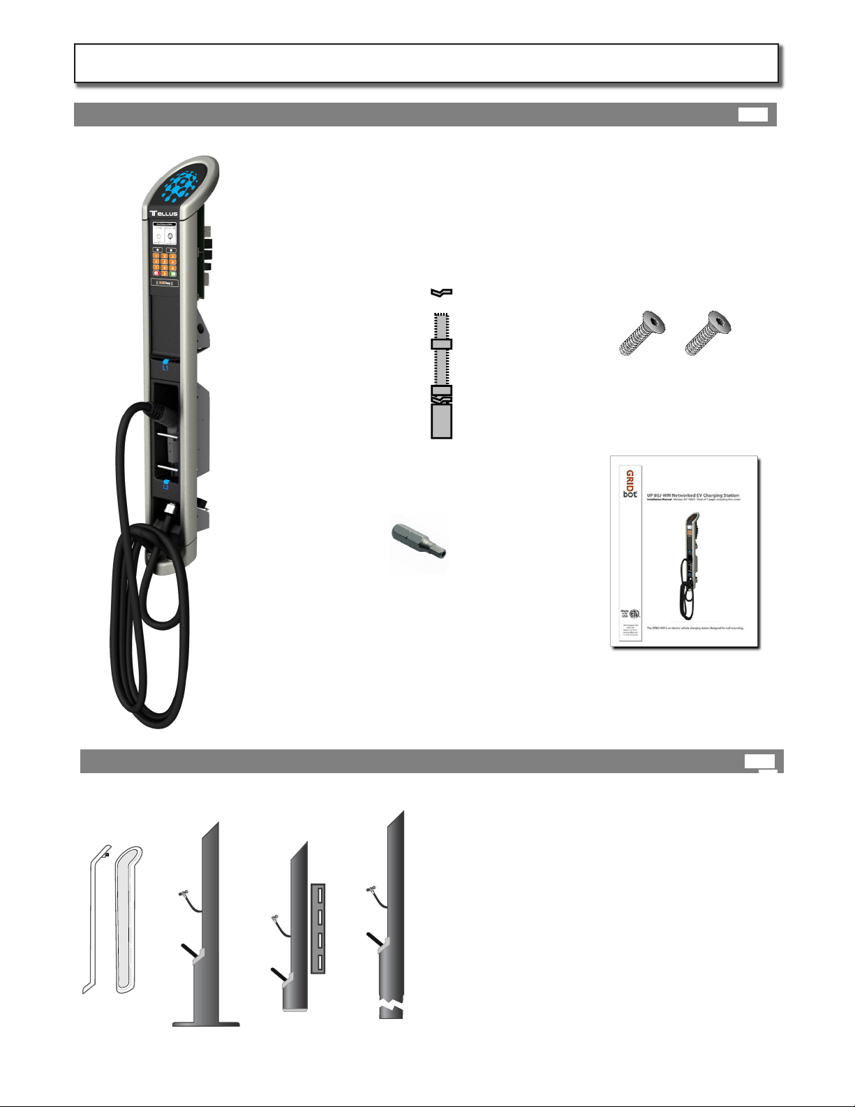
One (1) UP100J Station Head with
attached charging cables, couplers and base plate
One (1) Pin in hex security bit
Two (2) Pin in hex security bolts
One (1) Installation Manual
Base plate
Hardware
Set
Station housing posts must be ordered separately:
Pedestal
(UP-PMP)
Wall & Pole
(UP-WMP)
(UP-CMP)
Direct Burial
(UP-DBP)
Cover
(UP-COV)
The following tools may be needed:
- Short driver handle (for standard bits)
- Right-angle driver ratchet (for standard bits)
- Set of SAE wrenches
- Hole cutting drill bits to match conduit size
- Spirit Level
- Smart phone +“GPS coordinate converter” app
- Internet connected browser (tablet or laptop)
The following hardware may also be needed:
- Wall anchors and fasteners
- Washers
- Pad mount concrete anchors
- Anchor security hardware
Box contents
Other Items may be required for installation:
Page 4
Before You Start:
4B
4A
Other Items may be required for installation:
4B
KIT302-IM-20140501
NN N
G G
L1
L2
L1 L3L2
L3
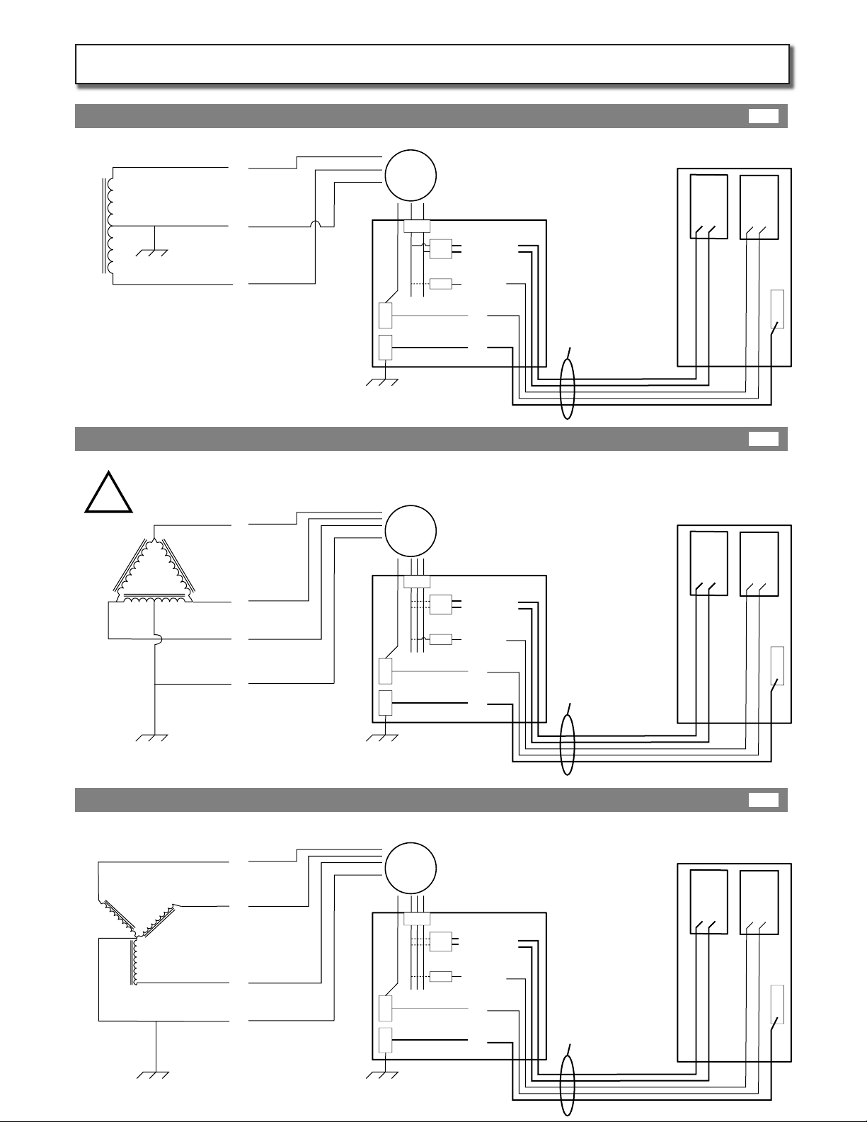
208V between any 2 Legs
Meter
Breaker Panel
120V between any Leg and N
40A
20A
Any Leg
Any 2 Legs
NN N
G G
L2
L3
“Stinger” or “High Leg”
NOT USED!
L1 L3L2
L1
240V between any 2 legs
120V between L1 and N
120V between L2 and N
! - 208V between L3 and N - !
Meter
Breaker Panel
40A
20A
L1 or L2
! Never L3 !
Never connect the station to L3. The 3rd Leg of delta is 208Volts with respect to Neutral and will trip the GMI !
L1 or L2
! Never L3 !
N
N N
G G
L2
L1
L1 L2
L1
L1
or
L2 N
L2
Meter
Breaker Panel
UP100J Station
40A
20A
G
L1 or L2
L1 & L2
240V 120V
Level-2 Level-1
L1
L1
or
L2 N
L2
UP100J Station
G
240V 120V
Level-2 Level-1
L1
or
L2
Any
Leg
Any
other
Leg N
UP100J Station
G
240V 120V
Level-2 Level-1
!
240V between L1 and L2
120V between L1 or L2 and N
Size conduit to carry ve
(5) wires:
(4) 30 Amp continuous
load rated conductors,
and (1) earth ground
Size conduit to carry ve
(5) wires:
(4) 30 Amp continuous
load rated conductors,
and (1) earth ground
Size conduit to carry ve
(5) wires:
(4) 30 Amp continuous
load rated conductors,
and (1) earth ground
240/120V SINGLE Split Phase (preferred service)
240V 3-Phase, DELTA-Connected, one leg center tapped (diculty balancing multiple stations)
208V 3-Phase, WYE-Connected (attention to balancing required for multiple stations)
Page 5
Service Wireing Options:
5A
5B
5C
KIT302-IM-20140501
If station housing uints have not already been installed and pre wired, complete this phase now. Follow the station
housing installation manual (UP-HIM) that comes with the housing units. Then ensure the following steps have been
completed before installing Station Head Units.
Run power conduit from panel to each station housing in accordance with local electrical codes and regulations. For
future upgradability, ensure that conduit is sized for a total of ve (5) wires! including four (4) current carrying conduc-
tors (connected to 2 double pole 40amp breakers) and one (1) Earth conductor.
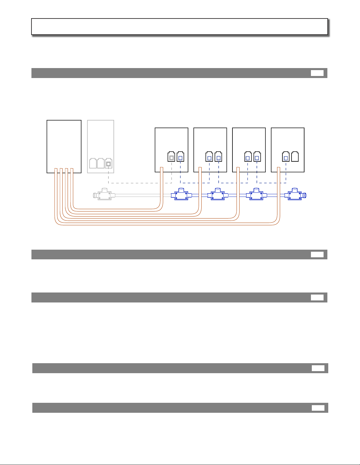
Use this diagram for a general overview of a typical site. Power conduit is always required. Data conduit between
stations is always required between multiple stations. Data conduit to the building is only needed if the onsite Verizon
2G data signal is poor. Alwasy test the Verizon signal before planning the site. (see page 11 for more detials)
If more than one station is to be installed in the same area, ax a data conduit T-box below each station housing, then
run data conduit between each. Size data conduit to carry up to 2 Cat5e cables each.
Pull Cat5 data cable in accordance with the number of station at the site. Leave 6ft of cable extending from top edge of
conduit wire protector in each station. Terminate all Cat5 Ethernet cables using identical wire (color) pattern on each
end (see page 11 for more detials)
First refer to page 5 for service based wiring options.
For UP100J head uints, size 5 electrical conductors according to NEC code using the following continuous load amperage
limits: Line1 (30 Amps continuous), Line2 (30 Amps continuous), Line 1 or 2 (16 Amps continuous), a Neutral (16 Amps
continuous) and an Earth Ground sized to match the largest current carrying conductor. Pull these 5 electrical conduc-
tors from the panel to each station leaving 40 inches of conductor extending from inside edge of conduit wire protector
Building
Internet
Router
(DHCP)
Service
Panel STN-1 STN-2 STN-3 STN-4
Data conduit
Required
Cat 5 cables
Building
data conduit
only required
if Verizon data
signal poor
Power conduit large enough for 5 wires each.
Electrical Conduit
Planning:
Pull Electrical Conductors
Data Conduit
Pull Data Cables
Page 6
Station Housing Installation (Wiring):
6B
6A
6C
6D
6E
KIT302-IM-20140501
Security
Bolt
Assembled
Base plate
Next insert the assembled base plate in to the
lower part of the housing and attach from the
back with the security bolt provided.
Adjust assembly as necessary before tightening
security Bolt
Base plate
Hardware
Set
Lock
Washer
Locking
Nut
Attach the base plate hardware (provided) to
the base plate by inserting it through the lock
washer and into the back of the plate.
Thread the hardware set into base plate until it is
nger tight.
Now tighten the locking nut down onto the base
plate with a wrench.
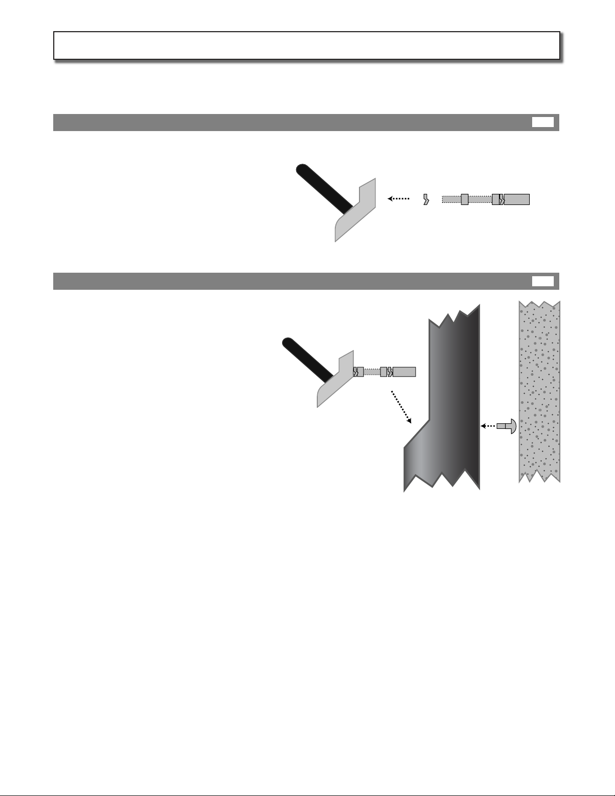
If a standard GRIDbot UP housing is not already installed, order and instal one by follow steps in housing Installation
manual (UP-HIM) followed by steps on page 6 of this manual.
Prepare Base Plate
Attache Base Plate to Housing
Page 7
Prepare Housing for Head Unit:
7B
7A
KIT302-IM-20140501

Leave head unit in protective packaging until housing and is
securely installed, conduit has been run, and wiring has been
pulled (electrical and data if required).
Once the housing and electrical work is done, open the end of
the box marked “open this end”.
Remove the round foam plug.
Remove the hardware bag rst, then slide the cable out of the
box rst.
Finally slide the station head together with its bag out of the
box
Retain the box and packaging in case it is needed for return or
swap of equipment. Store the box in a dry place.
If repacking is required. First place the station head the
anti-static bag. Secure neck of bag with tie.
Roll cable up in to an 15” diameter coil. Leave a 6”between
cable coil and head unit. Compress the coil as shown and tie
with cling-lm or plastic ties.
Please do not use sticky tape!
Insert the station head (in its bag) top down into the box. It will
be a tight t. Push it down until it reaches the bottom.
Next insert the compressed cable and push it down until it is 2
inches below the end of the box. Finally insert the round foam
plug.
Keep head in protective box
Unpack Head
Retain Box
Repacking if required
Page 8
Unpack Head Unit:
8A
8B
8C
8D
KIT302-IM-20140501
!
Station
Housing
Station
Head
Chassis
PEM nut
Mounted
Housing
Station
Head Unit
Grounding
Strap
Grounding
Strap
Level-2 Charging
Coupler(s)
Strain Relief
Loop
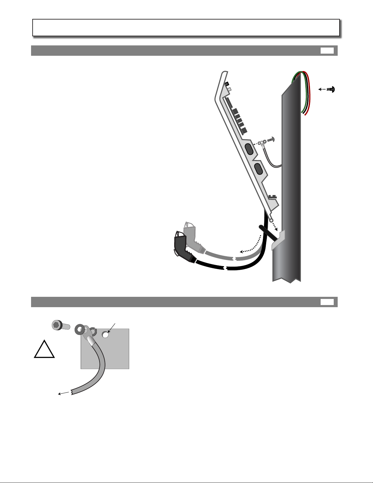
When attaching the grounding strap to the housing ensure that
the spring washer is completely compressed and that the
hardware is in the following order:
Bolt
Flat Washer
Strap
Spring washer
Head Chassis with embedded PEM nut
Unpack the Station Head., Lay it on a soft surface
near the station housing and unravel the charg-
ing cable(s).
Thread the level-2 coupler(s) downwards though
the black rubber strain relief loop near the base
of the station housing post. Pull most of the
cable(s) through.
Loosen the grounding strap hardware at the free
end of the strap. Check that the hardware order
is as shown below.
Insert the charging head into the mounted
housing post. The bottom of the station head
slides into the base plate slot.
Rotate the head up towards the housing post and
connect the free end of the grounding strap to
the housing. Tighten!
Insert Head
Grounding Strap Connections
Page 9
Station Head Installation and Grounding:
9A
9B
KIT302-IM-20140501

Station Head Unit
!
Before connecting power wires to the UP100J,
please carefully read the Wiring options section of
this manual on page 4. If you are not 100% sure of
the type of electrical service you are connecting to,
call your local utility for assistance.
First connect the shared ground conductor (green)
to the grounding bar on the station head unit.
NOTE: The station will not operate without a
successful ground path to the service panel.
Insert the 240VAC conductors into the spring
connectors labeled 240VAC and push down spring
tabs.
Insert the 120VAC conductors (Line, and Neutral)
into the spring connectors labeled 120VAC as
indicated and push down spring tabs.
Insert the terminated (RJ45 male) Cat 5 data cable
into the data input port at top of station until it
clicks.
Pull on all conductors to check that they are rmly
attached. Tie down conductors with provided
tie-downs.
5 Wires in from service
Earth Ground wire
connected to
grounding bar
Neutral
Line
Line
Line
120VAC
}
240VAC {
Grounding Strap
connected
to housing
Make Connections:
Page 10
Station Power Wiring:
10A
KIT302-IM-20140501

Master Client
Networked Networked Networked Networked
Networked Networked Networked Networked
Client Client
Before ordering Station Heads, It is best to go to the site with a 2G Verizon Mobile phone and check the verizon data
signal strength. This will help you to plan one of the “Master” station to be placed in a strong signal location. This
Master station will data connectivity to the all other stations connected to it with Cat 5 cable. If good Verizon signal is
detected, order one station head with -MSTR-V sux, and proceed with option 1 bellow. If not see Options 2 and C.
Most cost eective way to network stations is
via a Verizon Master station. All stations at the
site can be supported by one Master station
daisy chainged with Cat5 cable to the rest of
the stations (Client). Congure the site as
follows:
Regardless of the option above, Install data conduit and pull Cat5 cable
between each station in a linear daisy chain manor leaving 6ft of Cat5 in
each station. Each network segment between stations can have a maxi-
mum distance of 90 metres (300 ft).
Terminate cables with Rj45 male connectors. Standard termination for Cat5
(T568B) wires are in the order 1, 2, 3, 6, 4, 5, 7, 8 on the modular jack at each
end: orange/white, orange, green/white, blue, blue/white, green,
brown/white, brown.
Test each segment of terminated cable with a simple battery operated
Ethernet tester (aprox $20 and most computer supply stores).
If Verizon signals are not strong enough and
ATT has a good signal, you may replace the
master module with a kit. Order UP-COM-ATT
-3G. This kit comes with a bracket and
instruction for installing inside the rsts
station. Once again all other stations at the
site can be supported by this one Raven
Router station. Congure the site as follows:
If no mobile carrier has a good signal at the site you
can also support all stations by connecting them to
the building internet router. However , make sure
that the internet connection to this router is reliable.
Stations will not allow charging without an internet
connection.
If this is not possible, you will have to order internet
service from a local provider and have them install
the router on the wall next to the service panel. Then
congure the site as follows:
Test site mobile signal strength:
Instal data conduit and cable:
Option 1 : Master Verizon
Option 2 : UP-COM-ATT-3G Kit
Option 3 : Building Router
Page 11
Station Data Wiring:
11A
11E
11B
11C
11D
KIT302-IM-20140501
Building
Internet
Router
(DHCP)
STN-1
-MSTR
STN-2 STN-3 STN-4
STN-1 STN-2 STN-3 STN-4
Raven
Router
STN-1 STN-2 STN-3 STN-4

GRID
www.gridbot.net
key
www.gridbot.net
Station ID Front
Back
www.gridbot.net
Net Detect
GRIDkey
Back
“MASTER” Station“CLIENT” Stations
Option 1
Option 2 and 3
“NETWORKED” Stations
+
12 3
45 6
78 9
0
+
12 3
45 6
78 9
0
[ [ GRIDkey ] ]
[ [ GRIDkey ] ]
Enter New Station ID
MAC: 00:00:00:00:00:00
Current Station ID
New Station ID
000000
000???
NETWORK AUTO DETECT
NETWORK AUTO DETECT
Detecting MODEM........Found
IP ADDR: XXX.XXX.XX.X
MEID: XXXXXXXXXXXXXXXXX
Modem registered with cellular
network.
Contacting Server ......... Success
Signal Strength (max=10): 8
AGAIN ACCEPT
Detecting MODEM ........ Not Found
Detecting Network ........ Done
Setting station as CLIENT
Resolving IP ADDR ......Done
IP ADDR: XXX.XXX.XX.X
Contacting Server ......... Success
AGAIN ACCEPT
NETWORK AUTO DETECT
Detecting MODEM ........ Not Found
Detecting Network ........ Done
Setting station as NETWORKED
Resolving IP ADDR ......Done
IP ADDR: XXX.XXX.XX.X
Contacting Server ......... Success
AGAIN ACCEPT
Close station head and secure it using the top security bolt , then close the breakers feeding this station only. The
station will boot up. The main screen will come on and each port indicator LED light should turn blue.
Locate your installer GRIDkey tag labeled “Station ID” .
Place this tag over the “GRIDkey”logo on the front of
the station and move it around slowly until you hear a
beep.
A provisioning screen will appear. Use the key pad to
enter the full “ID Number ” located on the housing
label. Press enter. Use the Station ID GRIDkey again
to conrm the number on the screen matches the ID
on the station housing. Write the Station ID for each
station at the site on the from provided on page 13.
Then push the blue back button.
If you have chosen Option 1 (Onboard Master Verizon Modem)
then start with your master station.
Hold your Net Detect tag over the“GRIDkey”logo on the front of
the master station and move it around slowly until you hear a
beep. Then press the Yes button. It will detect the Master
Modem, pressent you with IP, MEID and try to register the modem
with the cellular network. This may take some time. If it fails,
wait 5 min and try again.
If it never registers, says“failure”,“Weak signal” , or a signal below
4. You may have to install an external high gain antena, or remove
the modem and resort to option 2 or 3.
After the Master is successful, record the MEID, then use your Net
Detect tag on each of the remaining stations. They should set
themselves as“CLIENT” and contact the server succesfuly.
If you have chosen Option 2 or 3 it does not mater which station
you start with, but you must rst make sure the router is working
as a DHCP server and has Internet access.
Hold your Net Detect tag over the“GRIDkey”logo on the front of
each station and move it around slowly until you hear a beep.
Then press the Yes button. It will detect the DHCP router get
asigned an IP adress and contact the server.
On failure check the router, rewall, then your data cable.
Close Station and Power-on:
Enter Station ID:
Network Auto Detect :
Page 12
Network Setup: (NOTE: stations will not work until networked)
12A
12B
12C
KIT302-IM-20140501

Go to http://www.gridkey.net , Login and register a new site with information you recorded on this form. Call +1 (707)
474 3800 for assistance with online registration.
Use this form below to make notes about the site and each station at the site:
Use a GPS reader, or smart phone with a decimal GPS software. Go to the site enterance where the dirver would enter
the site from the publice road and record the GPS reading. It will look like this (033.76220531,-118.13330135 )
Do the same infront of each station, and the service panel. Record all numbers below.
SITE
Street
Address
SITE Name
SITE
Driving
Directions
Stations:
ENTRANCE
GPS
,
. .
-
888
88888888
888
88888888
SERIVCE
PANEL GPS
,
. .
-
888
88888888
888
88888888
Station ID Qty L-1 Ports? Qty L-2 Ports?
GPS
,
. .
-
888
88888888
888
88888888
Station ID Qty L-1 Ports? Qty L-2 Ports?
GPS
,
. .
-
888
88888888
888
88888888
Station ID Qty L-1 Ports? Qty L-2 Ports?
GPS
,
. .
-
888
88888888
888
88888888
Station ID Qty L-1 Ports? Qty L-2 Ports?
GPS
,
. .
-
888
88888888
888
88888888
Station ID Qty L-1 Ports? Qty L-2 Ports?
GPS
,
. .
-
888
88888888
888
88888888
Station ID Qty L-1 Ports? Qty L-2 Ports?
GPS
,
. .
-
888
88888888
888
88888888
Station ID Qty L-1 Ports? Qty L-2 Ports?
GPS
,
. .
-
888
88888888
888
88888888
Station ID Qty L-1 Ports? Qty L-2 Ports?
GPS
,
. .
-
888
88888888
888
88888888
Station ID Qty L-1 Ports? Qty L-2 Ports?
GPS
,
. .
-
888
88888888
888
88888888
Station ID Qty L-1 Ports? Qty L-2 Ports?
GPS
,
. .
-
888
88888888
888
88888888
Station ID Qty L-1 Ports? Qty L-2 Ports?
GPS
,
. .
-
888
88888888
888
88888888
Station ID Qty L-1 Ports? Qty L-2 Ports?
GPS
,
. .
-
888
88888888
888
88888888
Station ID Qty L-1 Ports? Qty L-2 Ports?
GPS
,
. .
-
888
88888888
888
88888888
Station ID Qty L-1 Ports? Qty L-2 Ports?
GPS
,
. .
-
888
88888888
888
88888888
Station ID Qty L-1 Ports? Qty L-2 Ports?
GPS
,
. .
-
888
88888888
888
88888888
Station ID Qty L-1 Ports? Qty L-2 Ports?
GPS
,
. .
-
888
88888888
888
88888888
Station ID Qty L-1 Ports? Qty L-2 Ports?
GPS
,
. .
-
888
88888888
888
88888888
Station ID Qty L-1 Ports? Qty L-2 Ports?
GPS
,
. .
-
888
88888888
888
88888888
Note site and station details:
Get GPS readings :
Final Step - Provision station on network:
Page 13
Online Site Registration: (NOTE: stations will not work until registered)
13B
13A
11D
KIT302-IM-20140501
Table of contents


