GREPOW Tattu TA1200 User manual

Product Manual
MODEL:TA1200U
Compatible with Smart
and Standard LiPo Batteries
Multi Language Support
For Industrial Use

INSTRUCTION
WARNING
Thank you for choosing the TATTU TA1200 balance charger. Please read this entire
manual before charger operation. Keep this manual for future reference.
1. Do not use or leave charger in direct sunlight, expose it to rain high humidity or other
extreme weather conditions.
2. Keep charger away from heat, high voltage, water, flammable gas, corrosives and other
dangerous substances.
3. The recommended operating temperature range of this charger: 0°C~40°C/32°F~104°F
4. Only use charger on a stable surface with adequate ventilation during operation.
5. Do not cover the thermovent of charger or put battery on it during operation.
6. Do not attempt to charge NON rechargeable batteries. Do not attempt to charge an
unknown or unlabeled lithium battery without knowing its specifications.
7. Do not use the charger on flammable surfaces. Do not set charger on car seats or
carpets during charging.
8. Always confirm the charger settings match the battery being charged including
chemistry, cell count, voltage and amperage.
9. Do not attempt to charge or discharge a damaged battery.
10. Do not disconnect the charging cable during the charge cycle. Once the charge cycle
is complete, please do disconnect the charge and balance leads.
11. Ensure all connectors are clean and free of debris and moisture before making any
connections.
12. Do not disassemble or modify the charger in any way. There are no user serviceable
parts inside.
13. Do not operate charger during a lightning storm.
14. Do not allow children under 14 to operate this charger without adult supervision.
15. Do not short circuit or reverse polarity of charger. This will damage the charger.
16. Do not leave Charger unattended during charger operation.
17. When get fired, please do use dry-powder fire extinguisher instead of liquid one in
case of electric shock.
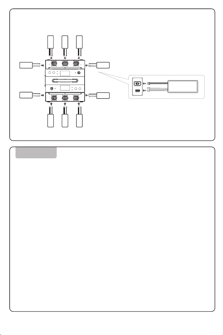
This charger is capable of charging 2 sets of lithium batteries simultaneously. The
maximum power output is 1200 watts per channel. User can select between Charging
mode and Maintenance mode. Charging current is adjustable between 10A, 20A and
30A. It also has over-current, over charging, over temperature, safety cut off, fast
equilibrium and status indicator functions. With the charging manager TA1200 and the
chargers UB-MG-Fast/UB5 combined, single charging manager can connect up to 5
sets of batteries simultaneously and charges alternately for the 5 sets of batteries on
basis of charging saturation from high to low. If the charger TA1200 connects with 2
charging managers UB5/UB -MG-FAST, It can charge 10 sets of battery simultaneously.
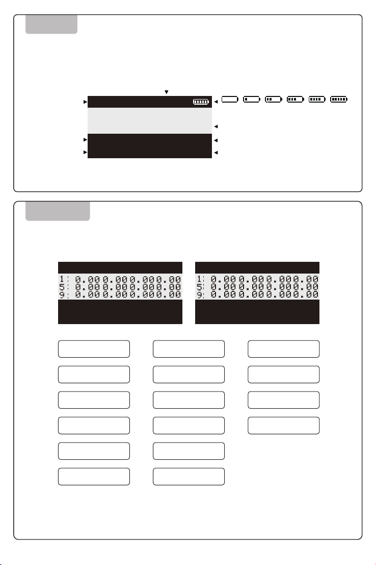
With double LCD display equipped, the charger automatically indicates real time
charging status, charging voltage, charging current, charging time, battery capacity and
cell voltage.
1

FIRMWARE UPGRADE
DIAGRAM
2
Power Switch
Please visit the TATTU website for firmware upgrades
Air Vent
LOGO
Balance Port
Power Supply
①
②
③
④
⑤
④
③
⑤
①
②
⑥ ⑦ ⑧ ⑨ ⑩
⑭
⑬
⑫
⑪
Current Switch
LCD Display
LED Indicator
Charge Button
Storage Button
⑥
⑦
⑧
⑨
⑩
Handle
Micro USB Port
Cooling Fan
AC Input
⑪
⑫
⑬
⑭
1.Please visit the TATTU website: www.grepow.com and download the latest
available firmware.
Connect power to the charging manager UB5
3.Connect a Mini USB cable from your computer to the UB5 Mini USB port.
4.Run the firmware and follow the prompts from the upgrade software.
5.After the upgrade is complete, the equipment will restart.
6.If there is an upgrade failure, please re-run the firmware upgrade procedure.

CONNECTIONS
3
Input power to charger: 100 VAC ~ 240VAC
Connectors connect
charger and battery
Adapters may be required for connection to the charger
● Always confirm that connection polarity is correct
before charging
● Always inspect batteries for physical damage
before attempting to charge
LiPo
AC Input
TA1200 Charger: XT90+AX200TA1200-A
Charger: AS150U+MX34020
TA1200-C
Charger: AS150U+MX3.0
TA1200-D
Charger: XT100+MX34020
TA1200 models and connection ports
LiPo

4
Connection diagram for UB-MG-FAST to TA1200 After UB-MG-FAST is connected TA1200
Connection diagram for UB5 to TA1200 After UB5 is connected to TA1200
Please follow the diagram below to connect the chargers to the charging manager.
Use the included 4 screws to secure the chargers to the charging manager. Each
charging manager can hold up to 2 chargers. There are 2 types of chargers that can
be connected, UB-MG FAST and the UB5.
NOTE:
Depending on which charger you
choose, please remove the small screws
in the diagram before installing and
tightening. The large screws that hold the
charger in place.

1. Startup and Self Test
OPERATION
5
LiPo
LiPo
LiPo
LiPo
LiPo
LiPo
LiPo
LiPo
LiPo
LiPo
LiPo
The TA1200 charging manager is a dual channel charger with independent
outputs. Each channel operates independently. The following is a single channel
example.
Be sure all cable connections are correct. Power the unit on. The LCD display, Led Indicator lights should
come on. When the charger completes, it’s self test the buzzer will sound.
2. Operation Modes
3. Setting Working Current
Charging Mode: Charging Mode will balance charge the battery quickly.
Maintenance Mode: When a battery has been on the shelf for a long period of time, it is recommended to
use maintenance mode. If the battery life declines or the battery is out of balance greater than 50mV,
Maintenance Mode will charge or discharge the battery using a small current to put the battery into proper
storage voltage.
Use the current switch to complete the current setting based on battery capacity.
4. Charging
Long press the charge button for more than 2 seconds to begin charging immediately, or charge will start
automatically after 10 seconds after connections are made.
1. Red Light On: the charger is charging the battery and the LCD display indicates real time charging
status.
2. Green Light On: Charging is complete.
Note: When using Continuous Working Mode, the charger automatically runs a series of operations.
These automatic operations include starting, stopping, testing and switching. When using Continuous
Working Mode, the charger will resume charging automatically if the battery is not removed within 30
seconds of pressing the stop button.
Connection Diagram:
TA1200 with UB-MC-FAST battery connections

ERROR!
ErrorError
OVER VOLTAGEUNDER VOLTAGE
REVERSE POLARITY
PROCESS INTERRUPTED
OUTPUT SHORT CIRCUIT
INPUT VOLTAGE ERROR
CHARGER FAILURE
BATTERY LOW VOLTAGE
BATTERY HIGH
VOLTAGE
CELL LOW VOLTAGE
CELL HIGH VOLTAGE
CELL CONNECT ERROR
CHARGER OVERHEATING
OVER POWER
MAX CURRENT
SAFETY TIMER
MAX CAPACITY
MAX EXT.TEMP
......
Charging/Storage
Standby/Error
Real-time charging
maintenance current
Real-time charging
maintenance voltage
Charging/maintenance time
Battery pack single-cell voltage display
The icon blinks half a second during charging or
maintenance and indicates the ratio of capacity.
When the capacity exceeds 999mAh, the unit of
capacity will be converted to "Ah"
SCREEN
0% 20% 40% 60% 80% 100%
The interface is displayed below:
MODE:CHARGE
CURRENT:
VOLTAGE:
19.9A
50.4V
TIME:
CAPACITY:
25:58
999 mAh
1:
5:
9:
4.20
4.20
4.20
4.20
4.20
4.20
4.20
4.20
4.20
4.20
4.20
4.20
NO.12 S
6
When the charger is used incorrectly or there is a failure, the charger will
display an error message. See examples below.
If the charger, is working the display will show the
charging channel. If the charger is not operating,
no information is shown on the display.

STATUS INDICATOR
Status Indicator
Green flashing LED
Red solid LED
Green solid LED
Green and Red flashing alternately
Standby
Working
Done
Error
G
G
R
SPECIFICATIONS
7
100-240V 18A 50/60Hz
Max50.4V Max.25.0A
100-120V Max Output Power 750W×2CH
180-240V Max Output Power 1200W×2CH
LiPo/LiHV/Smart Battery
12S
Dual Channel(10 Channels with 2 charging managers)
±20mV
Over Current Protection
Over Voltage/Under Voltage/Short Circuit/
Over Temperature/Reverse Polarity
0℃-40℃/32℉~104℉.
Cooling Air
Micro USB
≈325×190×280.5mm
≈9.2kg
Input
Output
Max Output Power
Type of Battery
Cell Count
Channel Count
Balance Tolerance
Input Protection
Output Protection
Working Environment Temperature
Cooling System
External Upgrade Port
Dimensions
Weight
Note: The specifications above are for your reference only.

Thank you for purchasing our TATTU charger. We do our best to provide you with
timely and satisfying support. Please contact us with any questions or concerns.
Disclaimer: What our manufacturing warranty does not cover.
8
SHENZHEN GREPOW BATTERY CO.,LTD
Chuangyi Road, Longhua Town, Bao An District, Shenzhen, China
China(HQ): www.grepow.com
US: www.genstattu.com
Germany: www.gensace.de
The product specifications and information mentioned in this instruction manual are for
reference only and are subject to change without prior notice.
COPYRIGHT SHENZHEN GREPOW BATTERY CO.,LTD
SUPPORT AND WARRANTY
WARNING!
RISK OF ELECTRIC SHOCK
DO NOT OPEN!
WARNING!
This product is warranted to be free from manufacturer defects for 1 year
from original purchase date. Please keep your original proof of purchase
for warranty purposes.
1. Damage caused by incorrect connections.
2. Damage caused by incorrect operation.
3. Damage caused by impact or drops.
4. Damage from disassembly or modification.
5. Internal damage from moisture, submersion, dust, dirt or other contaminants.
6. Signs of normal wear and tear, scratches dents and dings.
1.Do not attempt to operate this charger if you are
impaired in any way.
2.Do not allow children to be near this charger when
it is in operation.
3.Do not allow children to operate this charger.
4.Please turn the power off when the charger is not
in use.
5.This charger is for indoor use only.
Note: Any expense exceeding the original purchase price of the charger shall
not be borne by TATTU. We reserve the right to modify the contents of this
manual at any time with or without notice.
This manual suits for next models
4
Table of contents