TELNET GPONDoctor 9500 User manual

GPONDoctor 9500
User manual

Version control
VERSION DATE DESCRIPTION AUTOR
1 07/28/2021 Initial version Marketing department
Copyright © TELNET Redes Inteligentes S.A. 2021. All rights reserved. No part of this document
may be reproduced or transmitted in any way without the prior written consent of TELNET. All
other brands and trade names mentioned in this document are the property of their respective
owners.

GPONDoctor 9500
User manual
200080279-00 GPON DOCTOR 9500 user manual EN v0 WEB
3
Index
Version control....................................................................................................................................................2
1Introduction ...............................................................................................................................................5
1.1Document Structure.......................................................................................................................5
1.2Package Contents............................................................................................................................6
1.3How to install the GPONDoctor™.............................................................................................6
1.4General Technical Specifications..............................................................................................7
1.5General Technical Specifications..............................................................................................9
1.6External Buttons GPON Doctor™ 9500...............................................................................10
2Connection Procedures.......................................................................................................................13
2.1How to connect the GPON Doctor™ to a PON..................................................................13
2.2Connection to an Intermediate Physical Point of the PON Network........................17
2.3Connection to one End of the PON Network.....................................................................19
3Workflow..................................................................................................................................................21
3.1General Overview.........................................................................................................................21
3.1.1Menubar..........................................................................................................................23
3.1.2Toolbar.............................................................................................................................24
3.1.3Tabselectors....................................................................................................................26
3.1.4Statusindicator................................................................................................................26
3.2Real Time PON Status ................................................................................................................27
3.2.1RealtimePONtopology...................................................................................................27
3.2.2GEMportbandwidthmeasurements...............................................................................28
3.2.3GEMportselectionforusertrafficextraction.................................................................30
3.3How to Capture.............................................................................................................................32
3.3.1NormalStoreandDisplaycapture...................................................................................32
3.3.2RealTimeCapture............................................................................................................33
3.3.3TimeControlledStoreandDisplaycapture.....................................................................34
3.3.4Saveandloadcaptureddata............................................................................................37
3.4Exploring captured data ............................................................................................................39
3.4.1Capturetab......................................................................................................................40
3.4.2OMCItab..........................................................................................................................48
3.5Analysis Engine.............................................................................................................................52
3.5.1ConfiguringAnalysis.........................................................................................................53
3.5.2“ErrorDetection”Configuration......................................................................................55
3.5.3StartingandStoppingtheAnalysis...................................................................................58

GPONDoctor 9500
User manual
200080279-00 GPON DOCTOR 9500 user manual EN v0 WEB4
3.6PON Status......................................................................................................................................59
3.6.1TabLayout........................................................................................................................61
3.7OMCI Entities.................................................................................................................................65
3.7.1TabLayout........................................................................................................................66
3.8OMCI E/R Model ...........................................................................................................................71
3.8.1ONTSelection...................................................................................................................71
3.8.2Workingmechanics..........................................................................................................72
3.8.3TabLayout........................................................................................................................73
3.9Report Tab ......................................................................................................................................76
3.9.1TabLayout........................................................................................................................76
3.10Exporting data and results .......................................................................................................79
3.10.1ExportcaptureddatatoXML...........................................................................................79
3.10.2ExportanalysisresultstoHTML.......................................................................................80
3.10.3Exporterrorsreport.........................................................................................................82
3.11User traffic extraction.................................................................................................................83
3.11.1GEMportselectionforusertrafficextractionfromtheRealTimePON
Statustab.........85
3.11.2XGEMportselectionforusertrafficextractionfromtheUserTrafficExtractionPane..86
3.12User Defined Entities..................................................................................................................88
3.12.1EntityDefinition.xmlfileformat........................................................................................88
3.12.2
EntityDefininition.xml sample
...........................................................................................92
4System Update.......................................................................................................................................95
4.1Receiving the Update .................................................................................................................95
4.2Software Update...........................................................................................................................95
4.2.1Step0:Uninstallpreviousversion....................................................................................95
4.2.2Step1:DecompressUpdatePackage...............................................................................95
4.2.3Step2:Startinstallation...................................................................................................96
4.3Firmware Update..........................................................................................................................98
Glossary ........................................................................................................................................................... 102
5Contacts................................................................................................................................................. 105

GPONDoctor 9500
User manual
200080279-00 GPON DOCTOR 9500 user manual EN v0 WEB
5
1Introduction
1.1 Document Structure
This “User Manual” has been structured in a way that helps the reader to get acquainted
with how to use the GPON Doctor™. Starting from the basic “connecting the equipment
to the PON” it then moves onto the application flow; How and what to capture; Analysis
of the captured data and Extraction of User/Service Traffic.
The document is split in three main sections:
Introduction. This chapter describes the top-level features of GPON
Doctor™
together with some technical specifications. Its aim is to provide the
reader with a
minimum knowledge of what it is and how it can be used.
Connection Procedures. This shows the first steps to insert any GPON
Doctor™ within a PON, where it can be connected and how. The information
provided is important to be followed up to create a good environment
for
“Testing” and “Troubleshooting”.
Workflow. Finally, once everything is already setup, it is time to see how the
PON
runs, identify the different network elements, and debug all information
flows.
Within this chapter an explanation is given on how to capture the
information
and how it can be processed to understand what is going on.

GPONDoctor 9500
User manual
200080279-00 GPON DOCTOR 9500 user manual EN v0 WEB
6
1.2 Package Contents
GPONDoctor™9500:
PELITrolleycaseadaptedforthesecuretransportationoftheequipment:
o
ProtectionIP66MILC‐4150‐J
o
Systemtoequalizepressure
o
Protectionagainstimpact,vibrationsandhits.
o
FinishedinABS.
GPONDoctor™9500(SWapplicationalreadyinstalled)
Externalsplitter(7dBtothePON/7dBtotheGPONDoctor™).
Characterization
sheetincluded.
(2)SC/APC<‐>SC/UPCfibre(length3meters).
(1)AttenuatorSC/APC4dB.
(1)AttenuatorSC/APC8dB.
(1)AttenuatorSC/APC15dB.
(3)SC/APCfacetoface.
(1)Ethernetcable.
(1)Internationalpowersupply(110/220V)+powercable.
1.3 How to install the GPONDoctor™
The GPON Doctor™ is an autonomous system and as such, there is no need to install any
pieces of hardware or software. However, the Firmware and Application Software will
have new releases. To know how to upgrade your system so that it always has the latest
features please refer to the corresponding chapter of this manual.

GPONDoctor 9500
User manual
200080279-00 GPON DOCTOR 9500 user manual EN v0 WEB
7
1.4 General Technical Specifications
Capture system
Own implemented capture hardware independent of commercial chipsets: not
biased by manufacturers specific implementations.
Capability of connecting in a non-invasive way to any physical point of a GPON
network.
Distance synchronization system and automatic calibration: It calculates the
distance from the GPON Doctor™ analyzer to the OLT to synchronize with the
upstream and downstream channels.
The equipment can capture control data from the GPON network in both
communication directions where the following are included:
oOAM
oDBRu-DBA
oPLOAM
oOMCI
The maximum duration in the monitoring information capture process in full
mode can be under 60 minutes (depending on the configuration of the equipment
and the traffic density). In normal mode or real time, it can be of several days.
Analysis system
CST-GGS: The analysis system enables the reconstruction of the network topology
using the control and negotiation messages. The processed information is broken
down into the following fields:
oONTs that intervene with the fibre.
oStatus of the negotiation of the equipment involved.
oState machine for each network element.
PERB: Following the capture and subsequent deduction of the topology, a series of
monitoring rules are applied to inform the user of the evolution of the
communication in three aspects:
oDetection of anomalous situations in the negotiation process of the ONT
and the OLT.
oChecking the fulfilment of the standard by the ONTs and the OLT.
oEvaluation of the level of interoperability between devices.
Graphical E-R diagram of the OMCI entities.
oGraphical representation of the bandwidth allocation per ONT and T-
CONT.
oGraphical representation of the evolution in time of the assigned
bandwidth per T-CONT.

GPONDoctor 9500
User manual
200080279-00 GPON DOCTOR 9500 user manual EN v0 WEB
8
Storage
oThe captures can be downloaded to the internal hard disc for subsequent
analysis.
oThe captures can be stored in binary format.
oThe captures can be downloaded to an external storage system.
Hardware Equipment GPON Doctor™ 9500
oSelf-contained equipment: No need for keyboard or mouse.
o11.6” HD (1366x768) 16:9 Direct-View outdoor-readable display with
glove- capable multi touch and Gorilla Glass 3
oInternal storage system (128G/256G/510GBytes).
oRAM 8 GBytes
oDurable (MIL-STD-810G & IP-810G) portable form.
oVery Low weight: <1.8 kg.
oBattery Powered: more than 1 hour of full power operational time.
oBased on the Windows 10 Pro operating system.

GPONDoctor 9500
User manual
200080279-00 GPON DOCTOR 9500 user manual EN v0 WEB
9
1.5 General Technical Specifications
Optical parameters
Reception Sensitivity (dBm) Saturation
(dBm) Speed (Gb/s) λ(nm)
Capture card
(upstream) -28 -8 10
1270
Capture card
(downstream) -28.5 -6.5 (Damage
above -3) 10 1577
Splitting module
(ONT) -21 -1 10
1270
Splitting module
(OLT) -21.5 +0.5 10
1577
Attenuation (dB) Downstream
direction
Upstream
direction
Added to PON -7 -7
Added to analyzer -7 -7
General
Screen TFT 11.6-inch touch screen
Architecture X86 compatible
Operating system Windows 10 Pro
RAM memory 8 GB (version dependant)
Hard disc 128/256/512 GB SSD M.2 (Class 20) SATA (version dependant)
Connectors
Capture (downstream entry) SC/UPC
Capture (upstream entry) SC/UPC
Splitter (input and output) SC/APC
Ethernet Gigabit Ethernet (Extraction port)
RS-232 Left Side Bottom
USB Type-C Centre Side Bottom
USB 3.0 Centre Side Bottom
Micro SD card slot Right Side Bottom
Audio Right Side Bottom
Buttons
Soft On/Off (Security Button) Right Side Bottom
Ergonomics
Electrical feed 110/220V
maximum consumption 200W
Noise generated <20 dB

GPONDoctor 9500
User manual
200080279-00 GPON DOCTOR 9500 user manual EN v0 WEB
10
Table 1: Technical Specifications of the GPONDoctor
™
9500
1.6 External Buttons GPON Doctor™ 9500
Figure 1 Bottom side of the GPONDoctor™ 9500
1. Power connector port
2. RS-232 serial miniport
3. DisplayPort USB Type-C alternative/USB 3.2 mode first generation / power supply
4. USB 3.2 de first-generation Type-A with PowerShare
5. MicroSD card slot
6. Universal audio connector
7. Status led indicator / power button

GPONDoctor 9500
User manual
200080279-00 GPON DOCTOR 9500 user manual EN v0 WEB
11
Figure 2 Frontal view of the GPONDoctor™ 9500
1. Emisor de infrarrojo
2. Cámara
3. Indicador luminoso de estado de la cámara
4. Sensor de luz ambiental
5. Pantalla
6. Botón programable por el usuario 3
7. Botón programable por el usuario 2
8. Botón programable por el usuario 1
9. Botón de subir volumen
10. Botón de bajar volumen
11. Botón de aumento de brillo
12. Botón de reducción de brillo
13. Botón de bloqueo de rotación de la pantalla
GPONDoctor 9500
User manual
200080279-00 GPON DOCTOR 9500 user manual EN v0 WEB
12
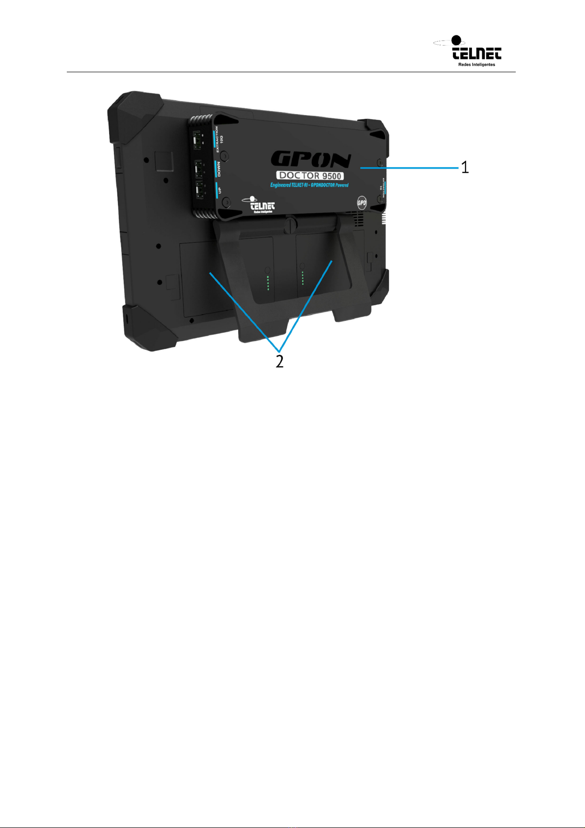
Figure 3 Back panel of the GPONDoctor™ 9500.
1. Capture module
2. Batteries location
GPONDoctor 9500
User manual
200080279-00 GPON DOCTOR 9500 user manual EN v0 WEB
13
2Connection Procedures
The GPON Doctor™ can be connected anywhere within the PON. By using a self-
calibration function, it recognises its position within the network and adapts itself
accordingly. However, there is a minimum set of steps that need to be considered for
an
optimum performance.
2.1 How to connect the GPON Doctor™ to a PON
The GPON Doctor™ is connected in parallel to the PON, meaning that the network traffic
(either upstream or downstream) does not pass through the GPON Doctor™.
By means of splitters, part of the optical budget is forwarded to the GPON Doctor™
without affecting the normal operation of the PON. The GPON Doctor™ needs two points
of connection to the PON, one to collect downstream information (from the OLT to the
ONTs) and the second to collect the upstream information (from the ONTs to the OLT).
Depending on the model of the GPON Doctor™ the connection is done in a slightly
different way.
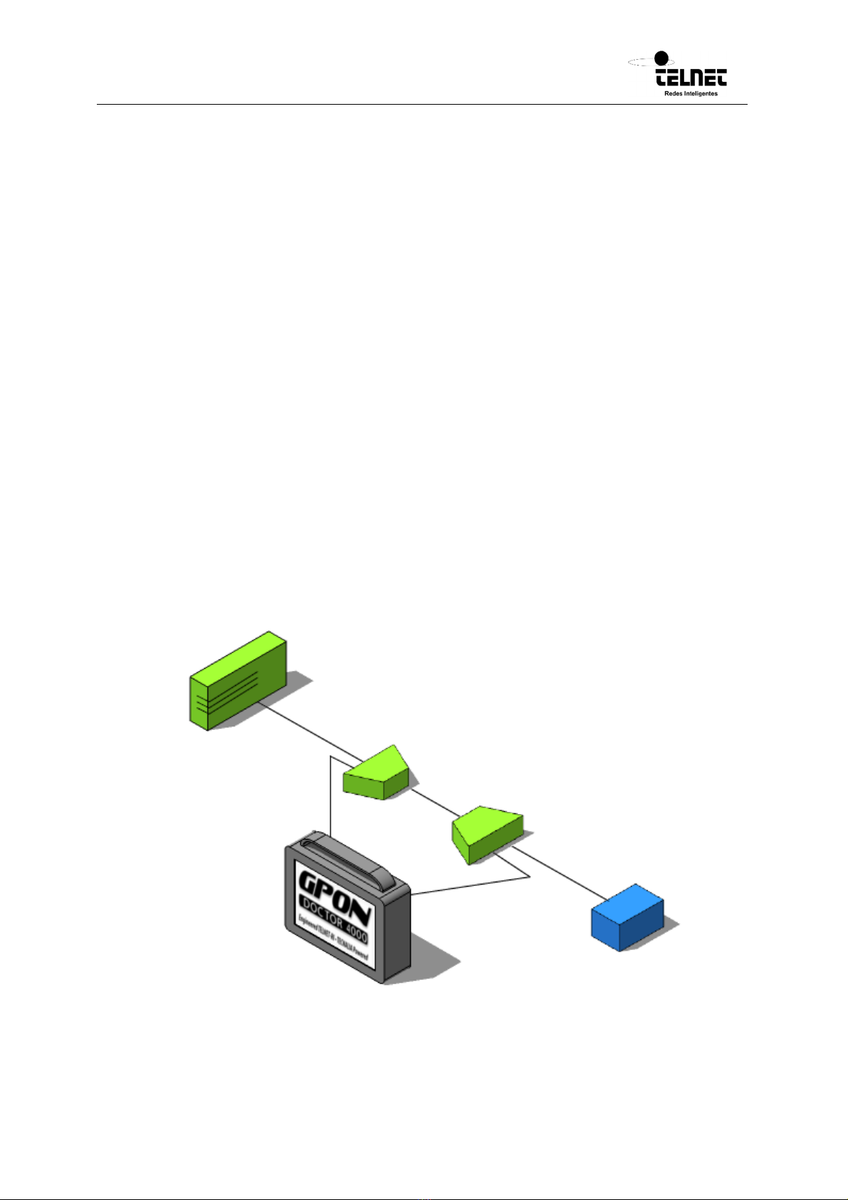
GPON Doctor™ 9500 has to be always connected to an external splitter (either the one
provided with the analyzer or through existing ones within the PON). See figure below.
Figure 4 Connection of the GPON Doctor™ 9500 in a PON by using external splitters
GPONDoctor 9500
User manual
200080279-00 GPON DOCTOR 9500 user manual EN v0 WEB
14
Therefore, the APC connectors located in the back of the GPON Doctor™ must be
connected to the splitters in the PON in the following way:
One of the outputs of the 1:n Splitter where the ONTs are plugged should be
connected to the DOWNStream connector of the GPON Doctor™ 9500.
One of the outputs of the 1:2 Splitter where the OLT is plugged should be
connected to the UPStream connector of the GPON Doctor™ 9500.
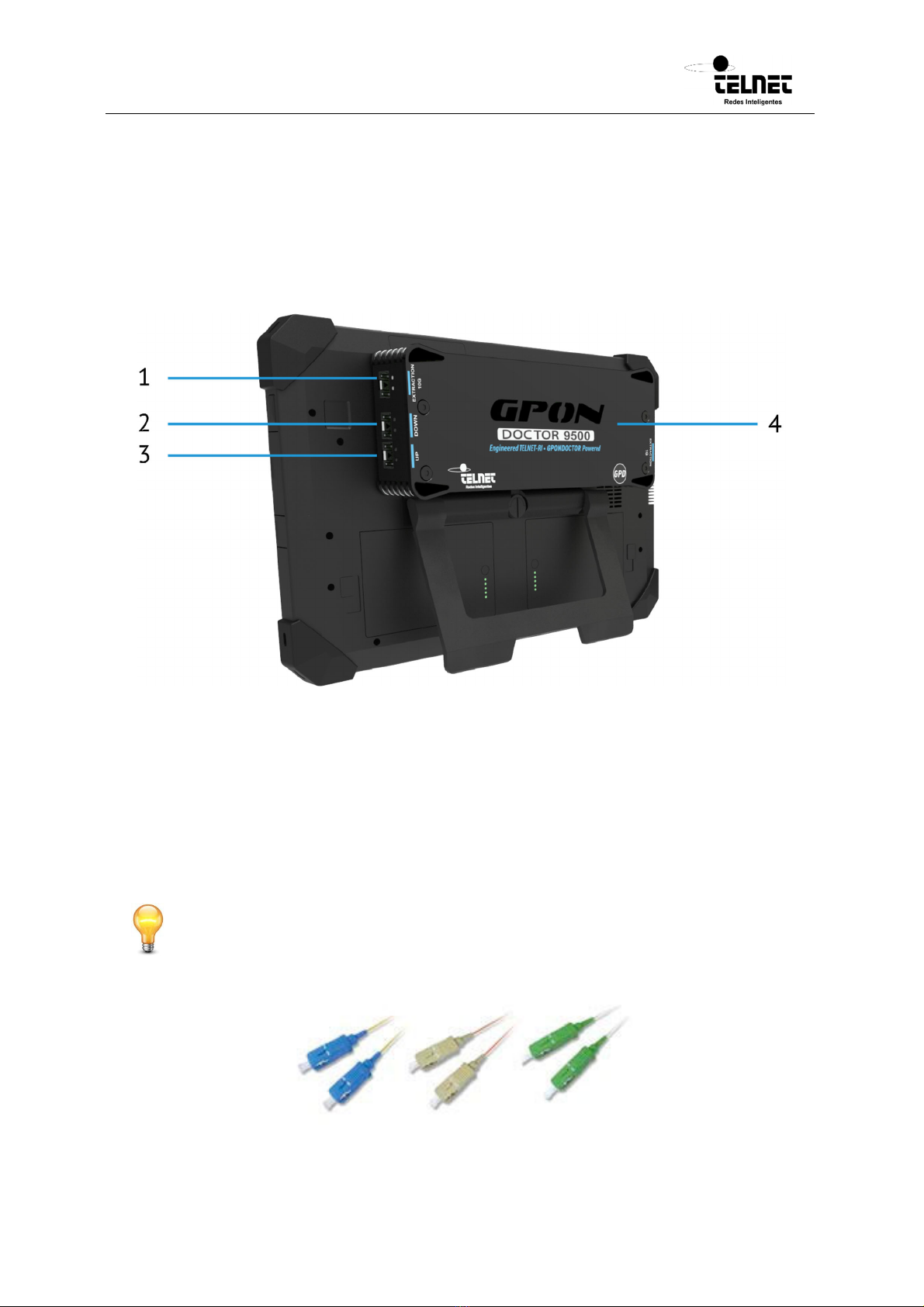
Figure 5 Backside of GPON Doctor™ 9500 where the Upstream and Downstram connectors are located
1. Extraction 10G
2. Downstream
3. Upstream
4. Extraction 1G
Always follow the Colour Code. Green endfaces are APC (Angled PC) and should be
plugged into Green connectors. Blue endfaces are UPC (Ultra Physical Contact) and
should be plugged into Blue connector.

GPONDoctor 9500
User manual
200080279-00 GPON DOCTOR 9500 user manual EN v0 WEB
15
The GPON Doctor™ 9500 are always provided with an external splitter. This splitter has
the following interfaces:
OLT interface. Green Plug (for APC endfaces). This is where the fibre connection
from the OLT should be plugged.
ONT interface. Green Plug (for APC endfaces). This is where the fibre connection
to the ONTs should be plugged.
Down interface. Green Plug (for APC endfaces). This interface must be connected
to the GPON Doctor™ 9500 DOWN Stream (UPC) interface.
Up interface. Green Plug (for APC endfaces). This interface must be connected to
the GPON Doctor™ 9500 UP Stream (UPC) interface.
Figure 6 External splitter connections
1. Introduces attenuation
The presence of splitters in the PON attenuates the optical signal and reduces the power
budget. To all intents and purposes, the architecture between the OLT and an ONT could
be simplified as a fibre with an attenuator in the middle. The value of this attenuator
depends on the number of splitting levels within the PON.
Connecting the GPON Doctor™ 9500 external splitter to the PON will add 7dB of
attenuation. Therefore, before placing the splitter into the network, it must be checked
that there is enough margin so that the normal operation is not impacted.

GPONDoctor 9500
User manual
200080279-00 GPON DOCTOR 9500 user manual EN v0 WEB
16
Figure 7 Impact of the splitter within the PON
If the optical power budget is not enough, the GPON Doctor™ will need to be connected
to the PON by means of already placed splitters (like in figure 5). The impact on the
network is caused by the splitters installed by the customer. 50/50 splitters reduce the
optical signal by 7dB.
In this case, to assure an optimal behaviour, it must be checked that the optical power
available to the GPON Doctor™ is higher than -28.5dBm in Upstream and -28.5dBm in
Downstream. Furthermore, a lower power level below ‘sensitivity’ or a higher power level
over ‘saturation/overload’ results in failure to capture the data correctly. Higher power
level can be adjusted to acceptable values by means of attenuators.
GPONDoctor 9500
User manual
200080279-00 GPON DOCTOR 9500 user manual EN v0 WEB
17
2.2 Connection to an Intermediate Physical Point of the PON Network
The GPON Doctor™ can connect to any physical point in a PON network and extract
information from both communication data flows (Downstream and Upstream). As shown
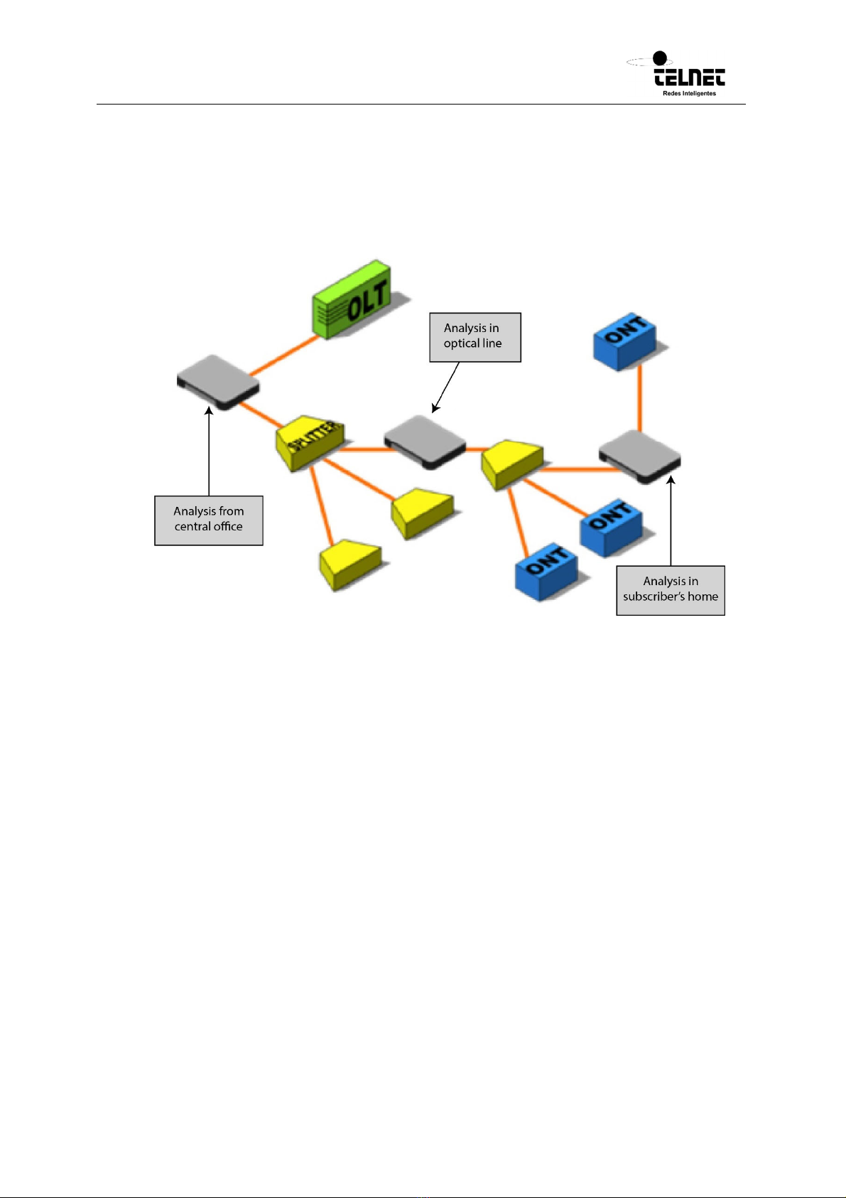
in Figure 8, the GPON Doctor™ can be placed in any intermediate point within a PON
network.
Figure 8 Connection to an intermediate point within a PON network.
Connecting the GPON Doctor™ to a PON intermediate point involves the following
stages:
Upstream/Downstream signal reception power measurement/inference at the
target capture point.
Calculation of the attenuation required for the capture card inputs.
Addition of the necessary attenuators (if needed).
Connection of the optical splitter to the fibres.
Optical power budget measurement
The objective of this first step is to calculate the optical power level at the PON inputs
of the external splitter. This process is specific to each direction of the communication.
Power in Downstream direction: The value is obtained by using a PON power
meter or by inferring the theoretical attenuation up to the physical capture point.
Power in Upstream direction: The estimation of this value is complex as each ONT
transmission is done at a different power and in “Bursts”.

GPONDoctor 9500
User manual
200080279-00 GPON DOCTOR 9500 user manual EN v0 WEB
18
Calculation of the necessary attenuation
The optical receivers of the capture card have a range of operational power levels that
must be respected. An excess or deficit of power would cause a loss of information or
capture errors.
The calculation of the attenuation must employ the following criteria for each direction of
the communication:
If the measured power is less than the sensitivity value envisioned in Tables 1 and
2 for the splitting module, the capture is probably not executed with guarantees.
Under that condition, it is recommended to select another target capture point
within the PON where the power budget is higher. Alternatively, optical amplifiers
could be used at the “Entry from OLT”.
If the optical power measured is greater than the saturation value envisioned in
Table 1 for the splitting module, the attenuation required has to be greater than
the difference between the value measured and the saturation value. For example,
a value measured of 5dBm at the “Entry from OLT” is 4.5dB over the saturation
value (+0.5dBm), therefore an attenuator of minimum 4.5dB is needed at the
“Entry from OLT” connector.
Attenuation of excess optical power
Once the required attenuations have been calculated for each direction of the
communication, they must be added to the optical splitting module connectors of GPON
Doctor™ 9500.
Figure 9 GPON Doctor™ 9500 splitter where the attenuators might be added.
1. Introduces attenuation
Connection of the optical splitting module to the PON network
GPONDoctor 9500
User manual
200080279-00 GPON DOCTOR 9500 user manual EN v0 WEB
19
This final phase is centred on the connection of the PON network to the optical splitting
module at the measurement point. This process is carried out by connecting the fibre from
the OLT to the “OLT optical splitter port” and the fibre directed to the ONTs to the “ONT
optical splitter port”.
2.3 Connection to one End of the PON Network
Figure 10 shows a scenario where the GPON Doctor™ analyzer is connected at one end of
a PON network. In this configuration, the analyzer can capture all downstream traffic
generated by the OLT but only the upstream traffic generated by the ONT connected
behind it.
Figure 10 Connection to one End of the PON Network.
Connecting the GPON Doctor™ to one end of a PON involves the following stages:
Upstream/Downstream signal reception power measurement/inference at the
target capture point.
Calculation of the attenuation required for the capture card inputs.
Addition of the necessary attenuators (if needed).
Connection of the optical splitter to the fibres.
Optical power budget measurement
The objective of this first step is to calculate the optical power level at the PON inputs of
the external optical splitter. This process is specific to each direction of the
communication.
Power in Downstream direction: The value is obtained by using a PON power
meter or by inferring the theoretical attenuation up to the physical capture point.

GPONDoctor 9500
User manual
200080279-00 GPON DOCTOR 9500 user manual EN v0 WEB
20
Power in Upstream direction: As there is only one ONT connected to the GPON
Doctor™, the power meter will have to measure the optical power between the
ONT and the GPON Doctor™.
The obtained results are an approximate value of the power from each of the directions
at the target capture point.
Calculation of the necessary attenuation
The optical receivers of the capture card have a range of operational power levels that
must be respected. An excess or deficit of power would cause a loss of information or
capture errors.
The calculation of the attenuation must employ the following criteria for each direction
of the communication:
If the measured power is less than the sensitivity value envisioned in Table 1 for
the splitting module, the capture is probably not executed with guarantees. Under
that condition, it is recommended to select another target capture point within the
PON where the power budget is higher. Alternatively, optical amplifiers could be
used at the “Entry from OLT”.
If the optical power measured is greater than the saturation value envisioned in
Table 1 for the splitting module, the attenuation required has to be greater than
the difference between the value measured and the saturation value. For example,
a value measured of 5dBm at the “Entry from OLT” is 4.5dB over the saturation
value (+0.5dBm), therefore an attenuator of minimum 4.5dB is needed at the
“Entry from OLT” connector.
Attenuation of excess optical power
Once the required attenuations have been calculated for each direction of the
communication, they must be added to the connectors of the capture card. Attenuations
must never be inserted into the optical splitting module connectors.
Figure 11 GPON Doctor™ 9500 splitter where the attenuators might be added.
1. Introduces attenuation
Table of contents
Popular Measuring Instrument manuals by other brands


Komshine
Komshine OTDR QX50 user manual

Agilent Technologies
Agilent Technologies 8453 Operator's manual

TSI Instruments
TSI Instruments VELOCICALC 9565 Series Operation and service manual

PCE Instruments
PCE Instruments PCE-125 Series manual

GHM
GHM GREISINGER GIA 20 EB Mounting and operating manual

TPS
TPS Aqua Series user manual

PIETRO FIORENTINI
PIETRO FIORENTINI RSE 1,2 LA N1 Use and maintenance manual

WINTACT
WINTACT WT63C instruction manual

Gill
Gill HS-50 user manual

Agilent Technologies
Agilent Technologies 16700 SERIES LOGIC ANALYSIS SYSTEM 16700 Product overview

HP
HP 70900B series Service guide

CONDTROL
CONDTROL Vector 100 user manual