Telpo TP-8S User manual

Telpo TP-8/16/24/32/64S Voice Gateway
User Manual
Telepower Communication Co., Ltd.
Tel: +86 0757-86299753
website: www.telpouc.com
Email: t[email protected]
Fax: +86 0757-86337898-770
Address: Room 201,Building A5, Hantian technology park, Foshan City, Guangdong, China
Latest revision:
2017-9-10
Revision No.:
V1.2

TP-8/16/24/32/64S User Manual Version No.: V1.2
- 2 -
Welcome to Use
Introduction
Thanks for purchasing our integrated access device (Voice gateway). Make sure
you have read this manual before use.
Applicable device’s model:
TP-8/16/24/32/64S
Matters related to readers
This manual is suitable for
Project planner
Equipment opener
Equipment maintenance personnel
Before consulting the manual, readers need to well know
NGN/IMS technology
TCP/IP Agreement
Ethernet Technology
Form 1 Prompts
Icon
Reminding
Type
Reminders
Reminding It means the important traits or operation guidance
Attention
It means it may do harm to people, or cause damage to the
system, or the business data to be disconnected or lost.
Warning It means it can lead people to be injured seriously.

TP-8/16/24/32/64S User Manual Version No.: V1.2
- 3 -
Operation Safety Rules
It is necessary to inspect the related power cables on a regular basis because
overloaded power sockets or broken lines and connectors all are likely to trigger
electric shock or fire. Please replace it immediately if there is any damage on surface.
Make sure to use the power adapter equipped with the device. Otherwise, it will
damage the device or make it operate abnormally.
Install the product in the place where is well-ventilated, and has no high temperature
and sunlight, to prevent it and other relevant components from being broken down
due to overheat.
Make communication devices avoid moisture and water. Or else, the device will
operate abnormally, or even provoke other dangers for short current.
Do not put the device on an unstable upholder.
Declaration
Without our permission, it is prohibited to reproduce or reprint any part of this
manual. We will not notify you of any alteration of this manual.
Thanks for purchasing our product! Please feel free to give us any criticism and
suggestion, we will deem them as the best encouragement and support for our work.

TP-8/16/24/32/64S User Manual Version No.: V1.2
- 4 -
Contents
WELCOME TO USE.............................................................................................2
INTRODUCTION ..................................................................................................2
OPERATION SAFETY RULES.............................................................................3
CHAPTER I PRODUCT INTRODUCTION ...........................................................6
1.1 Product Overview..................................................................................................................................6
1.2 Product Features....................................................................................................................................7
1.2.1 Function characteristics......................................................................................................................7
1.2.2 Voice characteristics...........................................................................................................................7
1.2.3 Network characteristics ......................................................................................................................8
1.2.4 Protocol standards ..............................................................................................................................8
1.2.5 Management maintenance..................................................................................................................8
1.2.6 Working environment.........................................................................................................................9
1.3 Networking Mode..................................................................................................................................9
1.4 Technical Specifications......................................................................................................................10
1.5 Device View........................................................................................................................................11
1.6 Panel Diagram.....................................................................................................................................12
CHAPTER II PRODUCT INSTALLATION ..........................................................14
2.1 Installation Preparation........................................................................................................................14
2.1.1 Open-box Inspection ........................................................................................................................14
2.1.2 Installation Precautions ....................................................................................................................14
2.2 Device Fixing......................................................................................................................................14
2.2.1 Cabinet-type Fixing..........................................................................................................................15
2.2.2 Plan Fixing .......................................................................................................................................15
2.3 Cable Connection................................................................................................................................15
CHAPTER III RAPID CONFIGURATION............................................................17
3.1 Preparation before Configuration........................................................................................................18
3.2 Cable Connecting................................................................................................................................18
3.3 PC’s IPAddress Modification .............................................................................................................19
3.4 Voice gateway Gateway Login............................................................................................................20
3.5 Voice gateway Network Settings.........................................................................................................22
3.6 SIP Server Parameters Setting.............................................................................................................23
3.7 SIPAccount and Password Setting......................................................................................................23
3.8 Ports Status..........................................................................................................................................24
3.9 Device Reboot.....................................................................................................................................25
3.10 Telnet Login ......................................................................................................................................25
3.11 HyperTerminal Login ........................................................................................................................26
CHAPTER IV DETAILED CONFIGURATION.....................................................29
4.1 Device Status.......................................................................................................................................30
4.1.1 System Information..........................................................................................................................30
4.1.2 Port Status ........................................................................................................................................30
4.1.3 WAN Status......................................................................................................................................31

TP-8/16/24/32/64S User Manual Version No.: V1.2
- 5 -
4.1.4 Telereport..........................................................................................................................................32
4.2 Network Settings.................................................................................................................................32
4.2.1 WAN Setting.....................................................................................................................................32
4.2.2 LAN Setting .....................................................................................................................................34
4.2.3 NAT Settings ....................................................................................................................................36
4.2.4 QOS Settings....................................................................................................................................36
4.2.4 Vlan Settings ....................................................................................................................................37
4.3 SIP Settings .........................................................................................................................................37
4.3.1 Basic Settings...................................................................................................................................38
4.3.2 Advanced Settings............................................................................................................................39
4.3.3 BlackAnd White List.......................................................................................................................41
4.4 Port Settings ........................................................................................................................................41
4.4.1 Basic Settings...................................................................................................................................42
4.4.2 Register Group Settings....................................................................................................................43
4.4.3 Voice Fax Settings............................................................................................................................44
4.4.4 Advanced Settings............................................................................................................................45
4.4.5 Ringing Polling Setting ....................................................................................................................46
4.4.6 Ringing Group Setting......................................................................................................................47
4.4.7 User Group Settings .........................................................................................................................47
4.5 Dialing Routing Settings .....................................................................................................................48
4.5.1 SIP Digit Map...................................................................................................................................48
4.5.2 Prior Digit Map ................................................................................................................................49
4.6 Global Parameter Settings...................................................................................................................50
4.6.1 DSP Settings.....................................................................................................................................50
4.6.2 SLIC settings....................................................................................................................................51
4.6.3 Timers...............................................................................................................................................52
4.6.4 POS settings .....................................................................................................................................53
CHAPTER V ADVANCED SETTINGS.............................................................53
5.1 NMS Settings ......................................................................................................................................54
5.2 Firewall Settings..................................................................................................................................56
5.2.1 Security Settings...............................................................................................................................56
5.2.2 Port Settings .....................................................................................................................................57
5.3 System Maintenance............................................................................................................................57
5.3.1 User Management.............................................................................................................................58
5.3.2 Software Updata...............................................................................................................................58
5.3.3 Config Backup..................................................................................................................................59
5.3.4 Default Settings................................................................................................................................59
5.3.5 Device Reboot..................................................................................................................................60
5.3.6 System log........................................................................................................................................60
5.3.6 Device information...........................................................................................................................61
CHAPTER VI APPENDIX...................................................................................62
6.1 Profile of Voice Command Line Interface...........................................................................................62
6.1.1 Command Line Entry.......................................................................................................................62
6.1.2 Command Line Prompts...................................................................................................................62
6.1.4 Auxiliary Function............................................................................................................................64
6.2 Detailed Explanations for Voice Command Usage..............................................................................65
6.2.1 Compressed Chip Setting Command Set..........................................................................................65
6.2.2 Network Parameter Setting Command Set.......................................................................................70
6.2.3 Protocol-related Parameter Setting Command Set ...........................................................................72
6.2.4 System Parameter Settings and System Tool Command Set............................................................74
6.2.5 CLI Cancellation Command.............................................................................................................79
6.2.6 System Restart Command ................................................................................................................79

TP-8/16/24/32/64S User Manual Version No.: V1.2
- 6 -
6.2.7 Parameter Display Command...........................................................................................................79
6.2.8 Parameter Effect-taking Command ..................................................................................................79
6.2.9 SNMP-related Parameter Setting Command Set..............................................................................80
Chapter I Product Introduction
The chapter focuses on introducing the networking modes and technical
specifications of Voice gateway.
Following are the main contents:
Product overview
Product features
Networking modes
Technical specifications
Exterior view
1.1 Product Overview
TP-64S product is a small-sized integrated access device which is researched and
developed by our company independently based on the next generation network (NGN).
it belongs to the terminal device of NGN access layer. Voice gateway provides the
traditional voice businesses and has the functions of data and voice processing. Namely,
data packet transfer, simulate voice processing and media stream transporting, as well as
support on existing and future new businesses of softswitch network. This series of
products are equipped with FXS (telephone interface), FXO (simulate relay interface) and
Ethernet interface. Based on the international standard protocol, we supply multiple
business accesses to consumers, and can satisfy users for the demands of voice, fax, data
and other comprehensive business accesses.
TP-64S product is used widely. It can be installed in many places, such as corridor,
house, phone bar and so forth. And it is helpful for a family, phone bar or small-sized
company in network, telephone and fax, etc.

TP-8/16/24/32/64S User Manual Version No.: V1.2
- 7 -
1.2 Product Features
1.2.1 Function characteristics
Multiple communication protocols: it supports session initiation protocol (SIP),
has advantages of strong expansibility, good compatibility and the like, and is
capable of interacting with all sorts of IMS platforms.
Perfect business supply ability: It supports distributed networking application,
cooperates with IMS platform to build IP voice access network, and supports IMS
value-added business, and inherits PSTN traditional business.
Reliable security: It supports to encrypt signaling and media stream respectively
and supports MD5 encryption technology. Meanwhile, it refuses illegal access and
business interference.
Firewall/NAT penetration: It adopts port mapping or special agent technology.
Penetrating firewall/NAT device can be disposed in the inside of local area network.
Flexible IP address configuration: It includes static configuration, DHCP dynamic
obtainment and PPPoE number dialing obtainment.
Simple management maintenance: It is based on WEB network management, and
also supports many configuration modes of CLI, TELNET and OMC (SNMP).
Telecommunication-level reliability: It can inspect failures and perform network
management alarm; and supports network re-connection after outage and SBC dual
homing. It is possible to register on the two SBCs of IMS and supports active
standby switch. Power source and interface are in possession of functions of
over-current protection and over-voltage protection.
1.2.2 Voice characteristics
Communication protocol: SIP (RFC3261, 3GPP)
Authentication ways: It supports authentication ways of SIP Digest, HTTP Digest
and IMSAKA.
Voice coding: G.711a/u, G.723.1 (5.3kbps/6.3kbps), G.729
Voice quality: voice activity detection (VAD), comfort noise generation (CNG),
Jitter Buffer dynamic adjustment, echo cancellation (complying with ITU-T
G.165/G.168), package loss compensation technology, DTMF detection/generation,
output/input gain control
Dialing rules: It supports E.164 coding rule, custom dialing rule and automatic
search agent server.
DTMF standard: Inband audio, outband over RTP (RFC2833/SIP INFO)

TP-8/16/24/32/64S User Manual Version No.: V1.2
- 8 -
Voice business: It supports hotline telephone, call transfer (forward transfer,
backward transfer) and call waiting.
Three-party services
Safe communication: It supports signal encryption and media encryption.
Billing function: It supports internet access private billing and POTS-standard
reversed polarity signal billing.
QOS support: It supports port priority control, IP TOS and 802.1p/q VLAN
Fax function: It supports T.30 fax, VBD passthrough fax and T.38 fax.
Modem support: It supports Modem business
1.2.3 Network characteristics
Network access: multiple network access modes (static IP, DHCP, PPPoE)
Network protocols: TCP/IP, UDP/IP, ARP/RARP, ICMP, IGMP, Telnet, HTTP,
DNS, DHCP, SNTP, FTP/TFTP and SNMP
Supporting network tools: Ping, Trace Route and Telnet Client
1.2.4 Protocol standards
IEEE 802.3 /802.3u 10 Base T/100Base TX
Main G.711A/U, G.723-r63, G.729 voice codec, SIP RFC3261IAX2
(Inter-Asterisk-eXchange V2)
TCP/IP: transmission control protocol/internet protocol.
RTP: real-time transmission protocol
RTCP: real-time transmission control protocol
VAD/CNG: voice activity detection/comfort noise generation
DHCP: dynamic host configuration protocol
PPPoE: Point-to-point protocol over Ethernet
DNS: domain name service
HTTP: Hyper text transfer protocol
FTP/TFTP: File transfer protocol/Trivial file transfer protocol
UDP: User data protocol
1.2.5 Management maintenance
Telephone configuration: It supports to inquire and set the relevant configuration
information by a simulate telephone.
Network configuration: It supports to upgrade the configuration by ways of HTTP,
TELNET and CLI
User right: It supports to carry out level-to-level administration for users and
administrators.

TP-8/16/24/32/64S User Manual Version No.: V1.2
- 9 -
Network management: It supports OMC (SNMP) network management.
Backup restoration: It supports to export and import the configured files.
Expansion function: Plate loading, device-level stack function
1.2.6 Working environment
Power input: 150~310V AC 47/63Hz
Environment temperature: -40~70℃
Relative humidity: 5~90% RH
1.3 Networking Mode
The next generation network (NGN) is developing and perfecting based on the soft
switch. TP-64S in the access layer is used in extensive fields, including network access,
telephone, fax and other demands of families, phone bars or small-sized companies.
1、Connected in the local area network with dynamic mode or static IP mode.
1)It is applicable to the companies or users built interior local area network;
2)TP-8/16/24/32/64S’s WAN port is connected with the hub or switch;
3)WAN port adopts dynamic IP (DHCP) mode or static IP mode according to
environment of local area network.
Figure 1-1 Connected in the Local Area Network with Dynamic Mode or Static IP
Mode
2、As a proxy server, it is responsible for dial-up access.
1)TP-8/16/24/32/64S’s WAN port is directly connected with xDSL(Cable) Modem.
2)As a proxy server, TP-8/16/24/32/64S is responsible for proxy access.

TP-8/16/24/32/64S User Manual Version No.: V1.2
- 10 -
Figure 1-2 Responsible for Dial-up Access as A Proxy Server
1.4 Technical Specifications
Item
8FXS
16FXS
24FXS
32FXS
64FXS
Size (mm)
W×H×D 350×290×44
mm
441×290×44
mm
441×290×44
mm
441×290×44
mm
442×280×43
.6mm
Weight 3.0kg 3.1kg 3.2kg 3.3kg 3.5kg
Max Power
Consumption
17W 20W 25W 35W 35W
Power Source DC12V.Extern
al adaptor
AC 85v~265V
47/63Hz
AC 85v~265V
47/63Hz
AC 85v~265V
47/63Hz
AC 85v~265V
47/63Hz
Device
Interfac
e
Upwa
rd
interf
ace
One 10/100
Base-T
One 10/100
Base-T
One 10/100
Base-T
One 10/100
Base-T
One 10/100
Base-T
Down
ward
interf
ace
One 10/100
Base-T
One 10/100
Base-T
One 10/100
Base-T
One 10/100
Base-T
Two 10/100
Base-T

TP-8/16/24/32/64S User Manual Version No.: V1.2
- 11 -
Netwo
rk
mana
geme
nt
interf
ace
One RS232(RJ45)
Voice Port 8 16 24 32 64
The registered
quantity of sip
extension agent 8 8 8 8 16
Interface Type
8FXS
16FXS
24FXS
32FXS 64FXS
Work
Temperature
-10℃~55℃
Storage
Temperature
-10℃~55℃
Humidity
(Non-condensed)
0~95%
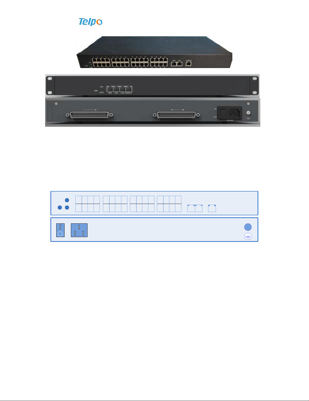
1.5 Device View
Figure 1-3 8FXS(Plastic shell)
Figure 1-4 8FXS(Iron shell)
Figure 1-4 16FXS
Figure 1-5 24FXS
TP-8/16/24/32/64S User Manual Version No.: V1.2
- 12 -
Figure 1-5 32FXS
Figure 1-6 64FXS
1.6 Panel Diagram
Here we take 32FXS for example to introduce the panel part of the product.
The panel diagram of 32FXS is shown as follows.
PWR POTS
SYS 1 3 5 7
2 4 6 8
9 11 13 15
10 12 14 16
17 19 21 23
18 20 22 24
25 27 29 31
26 28 30 32
WAN LAN CONSOLE
ON
OFF
100-240V 1A
50/60Hz
~
Figure 1-7 The Front Panel Diagram of 32FXS
The meaning of each kind of state of indicator light on the front panel of 32FXS is
shown as follows:
Sheet 0-1 Explanation for Panel indicator light and serial configuration port of
TP-8/16/24/32/64S.
Explanation on indicator light as follows. Indicator lights of FE port and CONSOLE interface are on
RJ45 of the port.

TP-8/16/24/32/64S User Manual Version No.: V1.2
- 13 -
LED Color Status Explanation
PWR Green
Often lighted
The device has been charged
Non-lighted The device runs out of power
SYS Green
Green Flashed The device is in service
Non-lighted The device runs out of power or operates abnormally
POTS Green
Green Lighted Any POTS port has off-hook
Non-lighted POTS port has no off-hook
LINK Green
Green Lighted FE port is in LINK status
Non-lighted FE port is not in LINK status
ACT Green Flashed FE port has data receiving and sending
Non-light FE port has no data receiving and sending
TXD Green Flashed CONSOLE interface sends data
Non-light There has no data sending
RXD Green Flashed CONSOLE interface receives data
Non-lighted There has no data receiving

TP-8/16/24/32/64S User Manual Version No.: V1.2
- 14 -
Chapter II Product Installation
This chapter focuses on deliberately explaining the matters with respect to installation
preparation, fixing and cable connection of Voice gateway. It mainly includes:
Installation preparation
Device fixing
Cable connection
Configuration environment establishment
2.1 Installation Preparation
Before IAD installation, make sure all components and conditions are complete.
2.1.1 Open-box Inspection
Open the box and inspect whether stuffs in the box are consistent with the list. If not,
please directly contact us.
2.1.2 Installation Precautions
Voice gateway can be installed on the desk or wall. Before installation, you are
required to pay attention to:
The place where IAD will be installed should meet the conditions to connect the
device with the external sites (such as: power line, network line, PC machine, etc.).
AC power socket should be single-phase three-core power socket, and ensure the
earth line is reliably grounded.
Where installation is executed should be well-ventilated, to help the device to
dissipate heat (the suitable environment is -10℃~55℃).
Installation place should be free from water, moisture and thunder, etc. (the suitable
humidity is 10%~95%).
2.2 Device Fixing
This section introduces various installation modes of Voice gateway to help users
choose what they need in accordance with their demands.

TP-8/16/24/32/64S User Manual Version No.: V1.2
- 15 -
2.2.1 Cabinet-type Fixing
Users are able to install the Voice gateway with big port in the standard cabinet
based on needs. If on-site installation is necessary, users are required to comply with:
1. First, clean up where the subframe will be put in the cabinet, tidy the former
cables and place them in the cable area at two sides of rack, adjust the supporting plates
of right and left subframes to be in place, and insert the combined nuts in the attachment
into square holes at front two sides of the cabinet (4 for each side);
2. Operated by two persons, slightly put the subframe on the supporting plate of the
cabinet , and push it in place slowly;
3. After positioning, use the combined screws (M6×16) with packing ring from the
accessories to tightly fix subframe and cabinet together.
Figure 2-1 Installation Completion Diagram
2.2.2 Plan Fixing
Take out four rubber mats equipped with Voice gateway and clip them into four
small holes on the device’s base plate, and then put the device on a stable and flat desk,
and make sure right and left sides have a good ventilation.
Reminding: Ensure Voice gateway to ventilate well at two sides; and
prohibit to place any object on it.
2.3 Cable Connection
1. General connection
By cable, voice gateway’s LAN port is connected with user’s computer, switch or hub,
and the WAN port is connected with Ethernet (for instance, ONU) or ADSL modem. FXS
port is connected with 32 pair of single-core copper connector. AC power port is
connected with AC power .

TP-8/16/24/32/64S User Manual Version No.: V1.2
- 16 -
Figure 2-2 TP-64S Cable Connection Diagram
Warning: for operating safely, do not energize the device until all
cables of it are connected and installation inspection is finished.
Reminding: It is suggested to utilize single-phase three cord power
socket of neutral connector or multi-function microcomputer power
socket. The socket should be reliably grounded. Do not use power
extension cords.
2. Cascade connection
Reminding:
In cascade connection, need to differentiate between primary
device and slave device
Turn on the Cascade Mode in primary device Web GUI
To keep the slave device software version is same with primary
device software version. Turn on the function to receive the
primary device testing packet in WAN port, and DO NOT turn
on the LAN port cascading mode in slave device. Then connect
slave device with primary device.
Warning:
Do not turn on LAN cascade in slave device.
After turn on the cascade mode in primary device, do not connect the
LAN port of primary device with local area network.
Take TP-64S cascading mode for example.
TP-64S primary voice gateway WAN port connects with upward ethernet network (like

TP-8/16/24/32/64S User Manual Version No.: V1.2
- 17 -
ONU)/ASDL modem by cable.
TP-64S primary voice gateway LAN port connects with slave voice gateway WAN port
by cable.
And so on, it can cascade three device including primary and slave devices
FXS ports(1-192 telephone ports) connect with user telephones by 6*32 pair single-core
copper connectors.
Figure 2-3 Two TP-64S devices connecting by cascade mode
Chapter III Rapid Configuration
This chapter mainly introduces how to simply configure SIP business function for Voice
gateway by WEB website, and also simply introduces Voice gateway’s other two login
methods, Telnet and Console. The aim is to let customers rapidly configure Voice
gateway in special circumstances. Main contents include:
Cable connecting, PC address modification
Network access settings
Rapid configuration
Voice gateway offers users an imaging and simple-operation WEB conversation
interface, so users are able to configure all functions of voice gateway just on the
common web browser without installing a special software, which is helpful for
consumers to lessen business opening cycle, quickly position failure and shorten failure
restoration time, so as to satisfy users and save operation and maintenance cost.

TP-8/16/24/32/64S User Manual Version No.: V1.2
- 18 -
3.1 Preparation before Configuration
Before configuring Voice gateway, you are required to first confirm:
1. Network access method:
2. Voice gateway’s WAN port supports PPPoE dialing, dynamic IP address and static
IP address.
3. SIP server address, port, account and password.
For example: Voice gateway data configuration information (enter the italic
information pursuant to the practical requirements).
Voice gateway gateway IP: 192.169.0.1 //static IP address/
Voice gateway subnet mask: 255.255.255.0
Routing gateway address: 192.168.0.1
SIP server address: 192.168.0.10
SIP server port: 5060
SIP account: 6400~6407
SIP account password: 123456
3.2 Cable Connecting
1.Connect the device power cord;
2.Link the upward network cable with Voice gateway’s WAN port;
3.Connect Voice gateway’s LAN port with PC, which is used to carry out
management;

TP-8/16/24/32/64S User Manual Version No.: V1.2
- 19 -
4.Connect route 32 RJ-11 business port with user’s telephone.
3.3 PC’s IP Address Modification
Connect computer with Voice gateway’s LAN port, and set its IP address as
192.169.0.2~192.169.0.254, subnet mask as 255.255.255.0, and gateway as 192.169.0.1.
It is fine not to fill in DNS or keep the initial value.
1. Open network connection, right click “local connection”, click property;
2. Open local connection property, choose “Internet protocol (TCP/IP)”, click
property (R);
3. Choose the option of “Use of the following IP address”, modify PC’s IP address
according to the practical needs.

TP-8/16/24/32/64S User Manual Version No.: V1.2
- 20 -
3.4 Voice gateway Gateway Login
Open IE browser and input LAN port’s default IP address (IP 192.169.0.1 or
192.169.0.235) in address column.
Enter username as admin and password as psw.iad (note the capital and small letters),
then import security code. It will immediately skip to gateway main interface once input
This manual suits for next models
9
Table of contents
Other Telpo Gateway manuals


