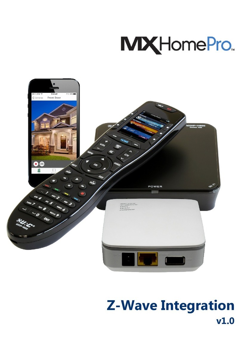
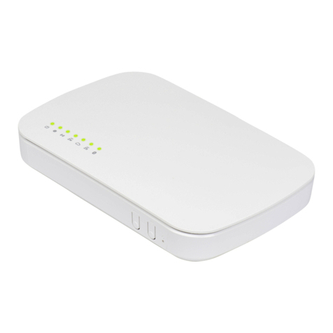
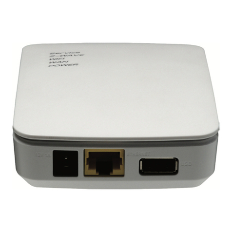
URC Total Control TRF-ZW10 User manual

TRF-ZW10
Owner’s Manual
Total Control TRF-ZW10
Owner’s Manual

Total Control TRF-ZW10
Owner’s Manual
Rev 1.6
Technical Suppor t
Toll Free: 800-904-0800
Main: 914-835-4484
techsupport@urc-automation.com
H o u r s : 9 : 0 0 a m - 5 : 0 0 p m E S T M - F
Overview....................................................................................................................... 1
Adding the TRF-ZW10 to a Project ........................................................................... 2
Network Di covery ..................................................................................................... 4
Upgrading the Firmware ......................................................................................6
Navigating the TRF-ZW10 Sub- tep......................................................................... 7
Device ....................................................................................................................8
Device - Working with Z-Wave .....................................................................11
Gateway Tool ...............................................................................................14
Device - Gateway Tool Option ............................................................15
Device - Controlling, Te ting, & Viewing Statu ..................................17
Node Information.................................................................................................20
Node Information - Viewing the Node Information ......................................21
Unknown Device ...............................................................................................22
Recovering an Unknown Device......................................................................23
Removing an Unknown Device.........................................................................24
Scene ...................................................................................................................25
Scene Controller ................................................................................................26
Scene Controller - A igning a Scene..........................................................27
Scene Controller Verification............................................................................29
TRF-ZW10 Programming - Including Device ...................................................... 30
SmartStart Inclu ion...........................................................................................34
SmartStart Provi ioning Li t ................................................................................... 36
TRF-ZW10 Programming - Excluding Device ..................................................... 38
Factory Default........................................................................................................... 40
A ociation Capabilitie /Command Cla e ....................................................... 41
Limited Warranty Statement.................................................................................... 42
Table of Content

1
Total Control TRF-ZW10
Owner’s Manual
Overview
The TRF-ZW10 is URC’s latest Z-Wave Plus™ gateway that allows for integration of
supported rd party Z-Wave™ lights, door locks, and other compatible devices.
This product can be operated in any Z-Wave network with other Z-Wave certied
devices from other manufacturers. All mains operated nodes within the network will act
as repeaters regardless of vendor to increase reliability of the network.
Non-Battery operated Z-Wave Plus™ devices act as Z-Wave repeaters and can help
extend the discovery/communication range of the TRF-ZW10.
This gateway can only be configured u ing URC oftware.
For additional hardware information on the TRF-ZW10, please refer to the device’s
Owner’ Manual.
URC Compatibility
The TRF-ZW10 is compatible with the following URC software platforms:
• Accelerator 3 (Expressway or Total Control Experience)
Requirement
• A compatible URC y tem must already be in place and operational prior
to integrating with the TRF-ZW10.
• Assure that all Z-Wave device are excluded and fully operational prior
to including with the TRF-ZW10.
• The TRF-ZW10 MUST be connected to the network via an
ethernet connection.
• It is strongly recommended that the TRF-ZW10 be congured with a
static IP address by using a DHCP/MAC re ervation.

2
Total Control TRF-ZW10
Owner’s Manual
Adding the TRF-ZW10 to a Project
The TRF-ZW10 can be added to any new or existing project. Perform the following steps
from within the Accelerator software:
1. Select Step 3: Add URC Device .
2. View the Current Room (i.e. Equipment Closet) and assure that it is the zone
where the TRF-ZW10 physically exists in the system.
. Beneath the Ba e Station column, locate and elect the TRF-ZW10.
This device can be selected by performing one of the following:
• Perform a double-click on the model name.
• Perform a ingle-click and then select Add to Room.
• Perform a ingle-click and then drag-n-drop this model name onto the
system’s Project Tree.
1
2
3
Use the Previou /Next
buttons to change Rooms.

3
Total Control TRF-ZW10
Owner’s Manual
4. Congure the Unified Module - Room Selection, Z-Wave offers Unied
Lighting, Climate, Access, and Scene Control module. Perform the to congure:
A. Select Unified Module: Click on either Lighting Control, Scenes Control,
Climate Control, or Access Control
B. Select Unified Module Room : Check the boxes of the Rooms/Zones that
need access to the module type selected on the previous step.
C. Repeat tep A and B for each module type required in the system.
D. Select Apply.
4
A
B
C
D
5. The Device Propertie displays, this window contains no actual values until
the device has been discovered on the network.
For instructions on how to di cover the
TRF-ZW10, please refer to page 4.
Click OK.
The TRF-ZW10 ha been ucce fully
added to the system and can be viewed on the
Project Tree.
5

4
Total Control TRF-ZW10
Owner’s Manual
Network Di covery
Anytime a new URC device has been added to the Project Tree, it must be defined on
the local network within Step 6: Network Setup.
For consistent and stable network communication, it is recommended that the
TRF-ZW10 be congured to a DHCP/MAC re ervation in the system’s local router.
Perform the following:
1. Select Step 6: Network Setup.
1
2. Select the URC Device sub-step.
. Locate and select the TRF-ZW10 from the list displayed on the left.
2
3

5
Total Control TRF-ZW10
Owner’s Manual
4. Click on Refre h.
This scans the local network for an available TRF-ZW10 and populates the
results on the right-hand side of the screen.
5. Select the TRF-ZW10 from the results list at the right, verify that this is the
correct device by matching the discovered MAC address with the one physically
marked on the device.
6. Click on A ign.
The IP addre and MAC addre of the device are applied to the device list
found on the left side of the screen indicating that the device has been
successfully discovered.
4
6
5

6
Total Control TRF-ZW10
Owner’s Manual
Upgrading the Firmware
Firmware upgrades are applied when downloading the Total Control conguration to
the system. However, this process can be performed manually by following these
steps after the TRF-ZW10 ha been di covered:
1. Select Step 6: Network Setup.
2. Select the URC Device sub-step.
. Locate and select the TRF-ZW10 from the list displayed on the left.
4. Select Set Device Network Option .
1
2
3
4
5. Click on Z-Wave Firmware Update.
A window with a tatu bar is displayed on the screen, do not interrupt
this procedure and do not di connect power from the TRF-ZW10.
5

7
Total Control TRF-ZW10
Owner’s Manual
Navigating the TRF-ZW10 Sub- tep
This section of the document provides information of the interface found in the
TRF-ZW10 sub-step of Accelerator 3.
In order to view this sub-step, click on Step 10: URC Sub y tem .
This sub-step includes four (4) sub-sections:
• Device : Use this section to Include/Exclude devices, test device functionally,
create associations, and congure device specic settings.
• Node Information: This section provides detailed information about a selected
Z-Wave device (node) such as manufacturer, association groups, command
classes, and much more.
• Scene : Use this section to create Z-Wave ba ed event , such as
Welcome Home, that can be triggered from any custom macro and/or
automated event.
• Scene Controller : Use this section only when a Z-Wave device has been
included, and it has scene controller functionality.
Scene Controllers allow a programmer to a ign Z-Wave Scene to Z-Wave
Scene Controller that are included in the y tem.

8
Total Control TRF-ZW10
Owner’s Manual
Device
This section is used to include/exclude Z-Wave devices, congure device settings,
test functionality/feedback, and more.
The Device tab is the default landing location when the TRF-ZW10 sub-step has
been selected.
Below are descriptions of each available button:
1. TRF-ZW10 Device : This list contains all of the Z-Wave devices that have
been included with the TRF-ZW10 gateway.
Devices can display here in three ( ) different colors, each color indicating a
specic status condition:
• Black: Connection status is normal.
• Red: Z-Wave device is offline.
• Gray: The Z-Wave device exists on the list but does not exist
within the TRF-ZW10 gateway.
Z-Wave devices are displayed on this list with a Node ID and an
End Point ID:
• Node ID: Example - Dining Room Light (8) - Represents the
value the TRF-ZW10 has assigned to the device.
This value is used when conguring associations, scenes, device
events, and troubleshooting.
• End Point ID: Example - AllLoadDimmer (264) - Represents the
node’s end point. Nodes can have multiple end points. This value
can be used when troubleshooting.
1

9
Total Control TRF-ZW10
Owner’s Manual
2. Refre h Node Info: Click on an available Z-Wave device
(i.e. AllLoadDimmer) then click on this button.
Once pressed, this TRF-ZW10 refre he the Z-Wave device’
information and status.
3. Include Node: Select a TRF-ZW10 located on the TRF-ZW10 Device
list and then select this button.
Once pressed, the Accelerator software prompts the programmer to begin
the proce of including a Z-Wave device.
For more details on how to include Z-Wave device with the
TRF-ZW10, please refer to page 0.
4. Exclude Node: Select a TRF-ZW10 located on the TRF-ZW10 Device
list and then select this button.
Once pressed, the Accelerator software prompts the programmer to begin
the proce of excluding a Z-Wave device.
For more details on how to exclude Z-Wave device with the
TRF-ZW10, please refer to page 8.
432

10
Total Control TRF-ZW10
Owner’s Manual
5. Tool : Select a TRF-ZW10 located on the TRF-ZW10 Device list and
then select this button.
Once pressed, the software displays the Gateway Tool window.
For more information on the options available within the Gateway Tools
window, refer to page 14.
6. Z-Wave Device Contextual Tool : The contents of this window vary
depending on the type of Z-Wave device elected from the TRF-ZW10
Device Li t.
This area can contain:
• Control Element : Buttons that directly control the selected
Z-Wave device such as “power on” when selecting a light switch.
• Statu Element : Areas of text that provide information ba ed
on the condition of a Z-Wave device such as the current
temperature when selecting a thermostat.
5

11
Total Control TRF-ZW10
Owner’s Manual
Device - Working with Z-Wave
The Device tab can be used to te t and further configure included
Z-Wave devices.
When an included Z-Wave device has been selected from the TRF-ZW10 Device
list, the Z-Wave Contextual Tool display the status and control buttons
supported by that device.
To view the status and controls of a Z-Wave device, perform the following:
1. Select Step 10: URC Sub y tem .
2. Locate and select the TRF-ZW10 ub- tep.
. Click on Device tab.
4. View the TRF-ZW10 Device Li t and elect a Z-Wave device
(i.e. Door Lock).
Select the End Point ID value, for example (267), to display the control and
status elements of the Z-Wave device.
This displays the control and tatu elements within the Z-Wave
Contextual Tool area.
1
2
3
4

12
Total Control TRF-ZW10
Owner’s Manual
3
Now that the Control and Statu options are available, this page describes all of
the available selections:
1. Rename: Enter a new custom name for the Z-Wave device, this affects
the name of the Endpoint ID display name.
2. Control & Statu Area: This section presents control options (if
applicable) of the Z-Wave device.
Control option vary depending on the type of included device,
such as unlock/lock commands for a Z-Wave door lock.
Press these control buttons to directly control the selected Z-Wave
device from within the Accelerator software.
The Status of the device can also be viewed here. The available status
conditions depend on the type of Z-Wave device that has been selected.
Lighting Dimmers present brightness and power feedback, Lighting
Switches provide power status, Door Locks display lock starts and more.
Different types of Z-Wave devices provide different options.
. Communication Feedback: Displays information that is being relayed
from the TRF-ZW10 to the connected Z-Wave device.
1
2

13
Total Control TRF-ZW10
Owner’s Manual
4. A ociation : Allow programmers to congure two or more Z-Wave
device to work in conjunction with each other such as an area that
requires three-way lighting.
5. Setting : Allows the programmer to congure device specic
parameters such as Delayed Off, Basic Set Value, and more. The
owner’s manual or supporting resources of the included Z-Wave device
may be required.
6. Tool : Displays options that allow the programmer to troubleshoot or
provide maintenance over a specied Z-Wave device:
• Remove Failed Node: If the node is unresponsive and cannot be
excluded, select this option to exclude the failed node from the
TRF-ZW10 Device List.
• Replace Failed Node: Select to exclude an unresponsive node
and replace it with another device.
• Update Network: Select to have the TRF-ZW10 rediscover
devices and update communication routes from the gateway to
the Z-Wave device.
• Update Firmware: Before selecting this button, assure that the
rmware update le has been retrieved from the manufacturer.
Click on this button to update the selected device’s rmware.
• Find: If supported by the device, this button makes a form of
physical identication (for example blinking lights) to assist in
locating the device.
4
5 6

14
Total Control TRF-ZW10
Owner’s Manual
Gateway Tool
The Gateway Tools window contains various advanced options that can be used
when troubleshooting the TRF-ZW10’s installation.
Perform the following steps from the TRF-ZW10 ub- tep of Step 10: URC
Sub y tem with the Device tab opened:
1. Select the TRF-ZW10 text found in the Z-Wave Device list.
2. Click on the Tool button.
. The Gateway Tool window is displayed.
12
3

15
Total Control TRF-ZW10
Owner’s Manual
Device - Gateway Tool Option
Below are descriptions of the available options found in this window:
• SmartStart Inclu ion: Allows the programmer to include SmartStart
upported Z-Wave device .
Make note of the device’s full DSK information as it is required.
[40 digit number]
• Backup Z-Wave Network: Allows the programmer to create a
backup (.bak) of the current TRF-ZW10 conguration.
This le can be stored within any folder of the local PC.
• Re tore Z-Wave Network: Allows the programmer to restore the
current TRF-ZW10 with a backup le (.bak).
The backup le must be stored on the local PC.
• Re et Z-Wave Network: When selected, this permanently era e all
of the information tore on the TRF-ZW10 and restores it to its
factory etting. This cannot be reversed.
• Reload Engine: When selected, this option “power cycles” the
Z-Wave network. No programming information is lost.

16
Total Control TRF-ZW10
Owner’s Manual
• Update Network (All Node ): When selected, this rediscovers all
available nodes and saves communication routes, removing any old
routes, to rebuild the Z-Wave network.
This can assist with communication issues if a Z-Wave device is
phy ically removed from it original location and set elsewhere in
the system.
Depending on the total number of device in the Z-Wave network,
the update process can take everal minute to complete.
• Learn Mode: Places the TRF-ZW10 into “learn mode” so a rd party
controller can include it. After Learn Mode is activated, the TRF's Learn
Mode DSK will be advertised in the application log. Enter it on the
including controller side.
• Controller Replication: Controller Replication is the process of
updating network information from a primary controller to
econdary controller , such as the node li t and routing
information. These steps are usually not required unle you have a
multiple controller on the network.
1. Start Add Mode on the primary controller.
2. Start Learn Mode on the econdary controller.
. All Z-Wave network relevant information will be updated for
the econdary controller.

17
Total Control TRF-ZW10
Owner’s Manual
Device - Controlling, Te ting, & Viewing Statu
Once a Z-Wave device has been included, it can be controlled from within the
Accelerator software on the local network.
Devices connected to the TRF-ZW10 gateway display on the TRF-ZW Devices
List and can be selected to reveal status and control options.
Certain devices, such as sensors, only offer status which provides information
on a device’s attributes.
Perform the following steps from within the Device tab of the TRF-ZW10
ub- tep to view the status and control elements of any included
Z-Wave device:
1. View the TRF-ZW10 Device Li t and elect a device, assure that
the end point ID is selected (i.e. Switch (265)).
2. Once selected, the Control and Statu area di play compatible
option of the Z-Wave device.
• Z-Wave Device - Lighting Switch: These types of devices
provide control options to turn the light switch On or Off.
Additionally, the software highlights the button that the device is
current set to (the example on the right is currently on).
1
2

18
Total Control TRF-ZW10
Owner’s Manual
• Z-Wave Device - Lighting Dimmer: These types of devices
provide control options to turn the light on or off.
Additionally, a lider i provided to adju t the brightne of the
device. The drop-down menu can also be used to set the device to
a specied percentage.
Feedback is provided by viewing the position of the brightness
slider and by viewing which button is highlighted (on / off).
Table of contents
Other URC Gateway manuals