TemperZone OPA 465RKTB Maintenance and service guide

GENERAL INSTALLATION
OPA 465–960 RKTB (c/w UC6)
Air Cooled Packaged Units - Reverse Cycle - R410A
Installation & Maintenance
1. GENERAL
Follow these instructions to ensure the optimum
performance, reliability and durability.
Units must be installed in accordance with all national and
regional regulations and bylaws. National Health and Safety
regulations must be followed to avoid personal injuries.
The appropriate local permits must be acquired and
adhered to.
Local regulations on maximum boundary noise need to
be considered when positioning the unit.
2. INSTALLATION
Refer to dimension diagrams below (Fig.1) for minimum
clearances. If multiple units are to be placed side-by-side
then allow at least 2m between coil faces.
2.1 Mounting
The unit should be fastened to a rm at horizontal
base using the holes supplied in the mounting
channels. When the unit is being installed on a roof it is
recommended that the unit is installed on a substantial
structure with vibration isolating springs beneath the
unit. These springs are not supplied with the unit.
Flexible duct connections are recommended between
the supply and return ducts and the unit.
Unit is shipped with wooden blocks installed under the
compressors. Ensure these blocks are removed from
the compressor feet prior to starting the unit
(not required for operation).
Factory lter slides are tted. Access to the lter access
door should be considered when designing return
and supply air ductwork. Access to the lters can still
be achieved by removing the return air access door,
however it is imperative that the rubber insulating
washers be retted to the screws prior to replacing
the panel.
2.2 Condensate Drain
The condensate drain should be ‘U’ trapped outside the
unit. The trap should have a vertical height of at least
100 mm. The drain should have a slope of at least 1 in
50 and must not be piped to a level above the unit drain
pipe. (refer g. 2)
003-000-029 02/17
SUPPLY
AIR
RETURN
AIR
OUTDOOR
AIR FLOW
OUTDOOR
AIR FLOW
OPTIONAL
WEATHER
HOOD
1000 MIN. CLEARANCE
500 MIN. CLEARANCE
ELECTRICAL
ACCESS
PANEL
1000 MIN.
CLEARANCE
FOR FILTER
ACCESS
500 MIN. CLEARANCE
2000 MIN. CLEARANCE
1000 MIN. CLEARANCE
FAN
ACCESS
PANEL
Figure 1.
OPEN
DRAIN
MINIMUM
SLOPE
20 mm PER m
(1 IN 50)
100 mm
MINIMUM
200 mm
APPROX.
'U' TRAP
100 mm
APPROX.
VENT PIPE
FOR LONG
CONDENSATE
DRAIN RUNS
Figure 2.

- 2 -
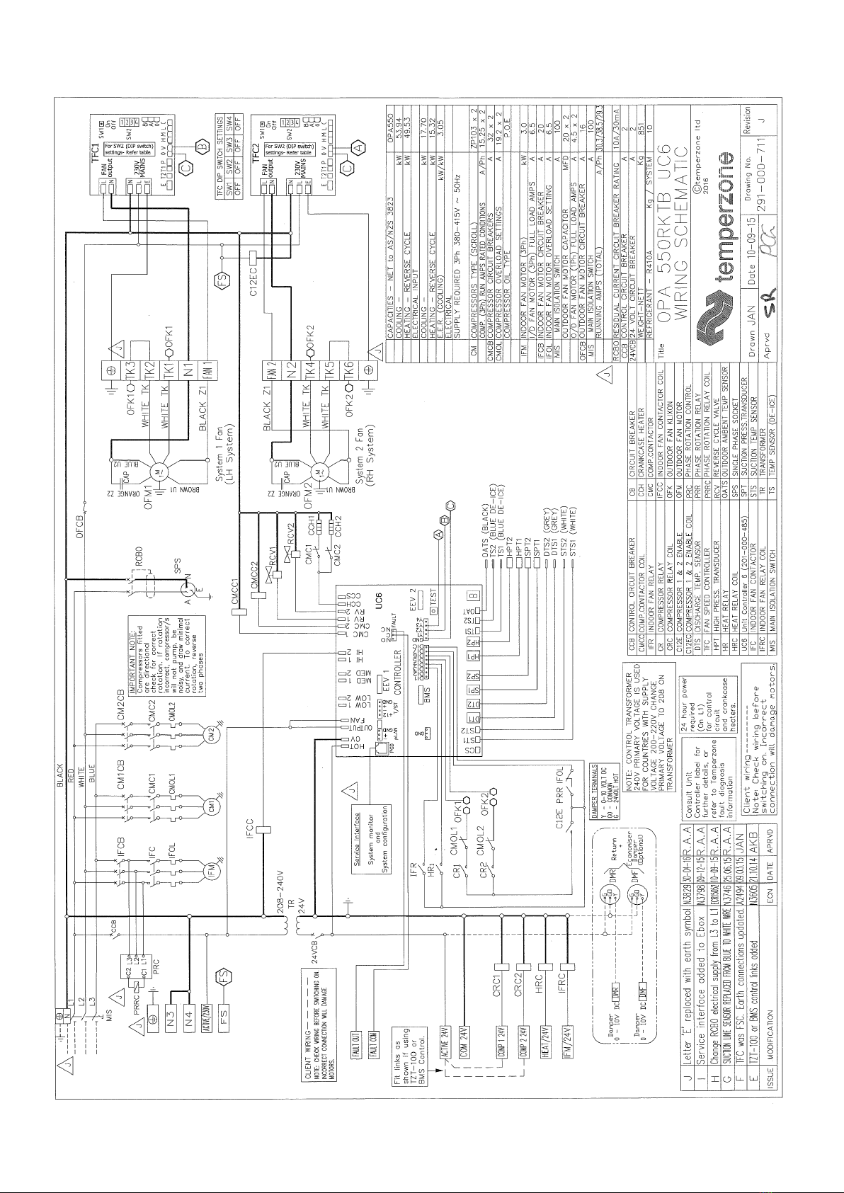
REFRIGERATION SYSTEMWIRING
3. REFRIGERATION SYSTEM
3.1 General
The OPA 465–960 models have two independent
refrigeration circuits and two compressors to provide
the exibility and economy of two stage operation, i.e.
utilising one or two circuits as conditions vary, plus the
advantage of staggered starting.
Units are supplied with a UC6 service interface display
tted for ease of service, maintenance and trouble
shooting. Operating pressures and status can be read
from its various display screens (refer user manual).
Each refrigeration system has been charged with
HFC-410A (R410A) refrigerant; refer wiring diagram
specication table for amount. This charge is based
on nominal capacity, nominal conditions and nominal
airow and is sufcient under these conditions to
maintain a refrigerant superheat of approximately 6
Kelvin. If the unit is installed in subtropical or tropical
conditions, has a high fresh air content or has been
installed with maximum supply
air quantity, the superheat should be checked and if
found to be above 6 Kelvin, refrigerant may need to
be added to the system to return the superheat to the
factory required state. These readings should be taken
with each stage operating independently and after the
space has achieved conditions. The additional charge
should be recorded for future reference.
3.2 Compressors
The compressors are directional scroll type. The
compressor lubricant is polyolester oil (POE). Note, this
oil absorbs moisture quickly if exposed to open air.
On commissioning, the compressors must be checked
for correct rotation (refer Start Up Procedure). A
time delay prevents simultaneous starting of the
compressors.
3.3 Economiser (Option)
If the outdoor air temperature or heat (enthalpy) content
preferably, is below that of the return air the fresh air
damper opens and the return air damper closes to
provide the rst stage of cooling. The fresh air damper
should return to minimum setting and the return air
damper open before the compressors are allowed to
operate to provide further cooling.
3.4 Setting Supply Air Flow
If the indoor air returning to the unit is regularly
expected to be above 50%RH, then the coil face
velocity should be limited to be 2.5 m/s or less (refer Air
Handling graph on page 5).
High humidity levels can occur in tropical or subtropical
conditions, and/or when heavily moisture laden fresh
air is introduced. Select a fan speed that avoids water
carry-over problems.
In a free blow or low resistance application, beware
of exceeding the fan motor’s full load amp limit (refer
wiring diagram).
The indoor air fan motor is tted with a factory set
adjustable pitch pulley. Instructions for the adjustment
of pulleys is included on the back page of the supplied
Commissioning Sheet. One revolution of adjustment is
equal to approx. 7% change in air volume ow rate.
4. WIRING
4.1 Electrical Requirements
Electrical work must be done by a qualied electrician.
DANGER LIVE ELECTRICAL CONNECTIONS. ONLY QUALIFIED
PERSONS WHO ARE COMPETENTLY TRAINED SHOULD
PERFORM SERVICE AND MAINTENANCE TASKS.
The unit must be wired directly from a distribution board
by means of a circuit breaker or H.R.C. fuse, and a
mains isolator provided - preferably close to the unit.
Note: DO NOT USE REWIRABLE FUSES.
The OPA unit is provided with a 24V ac control circuit
thermostat (TZT Optional), on/off switch and/or time
clock, eld supplied and tted. The control transformer
240V primary is used for countries with 230-240V
power supply. Alternatively control can be via a Modbus
connection.
For countries with supply voltages 200-220V, change
the primary voltage on the transformer to 208V.
Standard units are suitable for use with thermostats
with either manual Heat/Cool selection or automatic
changeover subject to the contact ratings of the
thermostats.
A 24 hour power supply to the compressor crank case
heaters is required, otherwise the warranty is void.
4.2 Unit Controller (UC6)
The temperzone Unit Controller 6 (UC6) combines the
µPC controller board from Carel plus an interface board
to connect temperzone standard sensors and plugs.
The UC6 receives requests such as “Unit On/Off”,
“Start 1 or 2 compressors”, “Activate HEAT (Reverse
Cycle)” and transfers these requests to the outputs after
enforcing safety timers. The UC6 ensures unit safety by
continuously monitoring input signals such as pressures
and temperatures. Beside the normal controls and unit
safety the UC6 has many other functions, for example
head pressure control, capacity control, superheat
control, serial communications and more.
The Unit Controller provides system protection
functions such as coil frost protection, de-icing, high
head pressure and low suction pressure cut-out. It also
protects against rapid cycling of the compressor(s) and
loss of refrigerant. The UC6 regulates the superheat
of the refrigeration system by controlling the position
of an electronic expansion valve (EEV). Various
methods of head pressure control (or limiting) are
employed in temperzone units. The particular method
used varies from model to model, but is also handled
by the Unit Controller. In combination, these features
deliver optimised performance across a wide operating
temperature range.
As a result of the UC6’s control of these inter-related
functions, the outdoor fans may take some time to start
rotating after each compressor start. They may also run
on when the compressor stops. The fans will stop during
a de-ice cycle and the speed will vary either smoothly,
or in steps, in order to protect against excessively low or
high head pressure.
Refer to temperzone for operation & fault diagnostics
information OR www.temperzone.biz.

- 3 -
START UP PROCEDURE
5. STARTUP PROCEDURE
5.1 Pre -Startup
1.
Leave the external temperature controller on/off switch
in the off position and close the unit’s mains isolating
switch. A four hour delay period is required to allow the
crankcase heaters to drive any liquid refrigerant out of
the compressor oil.
2. Check that the shipping blocks beneath each
compressor have been removed and that each
compressor is secure on its mounts
3. Check that all fan motors are free running.
4. Check that the thermostat is correctly wired to the
unit and is set at the desired temperature.
5. Check that the air lters have been correctly installed
if tted.
6. Check air diffuser dampers are open.
7. Check and tighten all electrical connections.
5.2 Commissioning
Use the supplied Commissioning Sheet to help you
complete the following procedure:
1. After the four hour delay period has crankcase heater
thermostat has been reconnected.
2. Check the supply voltage between each phase
and neutral.
3. Compressors tted are directional. Check for correct
rotation. If rotation is incorrect the compressor will
not pump, be noisy, and will draw minimal current.
To correct motor rotation, change the phasing at the
main power terminal. If changing the phasing, check
the indoor air fan then runs in the correct direction
also.
4. Measure the current draw on each phase to the
compressor motors and measure the current draw
of each fan motor. Check all readings against the
specied values in the wiring diagram.
5. Use the on board UC6 Service Interface display
(if supplied) or t R410A compatible gauges and
measure the suction and discharge pressures of both
refrigeration circuits.
6. Check that the outdoor air fan motors are running
smoothly.
7. Test the operation of the reversing valve in cooling
and heating mode (refer Commissioning Sheet).
8. Check the supply air ow at each outlet after
commissioning of fans
9. Check the tightness of all electrical connections and
sign the check label.
10. Touch up any outdoor unit paintwork damage to
prevent corrosion
OPERATION
6. OPERATION
6.1 Remote on/off
The remote on/off function can be enabled or disabled
by using the UC6 Service Interface (option).
When the function is enabled the remote on/off signal
must connect to input DI7, signal return is DIC1. The
remote on/off signal must be an external voltage free
switched relay contact.
The unit is active when DI7 is connected to DIC1.
6.2 High pressure protection (HP)
If high pressure transducers are connected to inputs
HP1 and HP2 then a compressor is switched off when
the discharge line pressure reading exceeds 42.0bar.
Instead of high pressure transducers some systems
may be tted with high pressure switches. These
also connect to inputs HP1 and HP2. When a high
pressure switch activates (electrical circuit opens) the
compressor is stopped.
Similarly, if the condensing temperature reported by an
outdoor coil temperature sensor (connected to TS1 and
TS2) reports a coil temperature above +66°C (cooling
mode) the compressor is switched off.
The UC6 will automatically reduce capacity of a digital
scroll compressor before the maximum value of 42bar /
66°C is reached.
When a compressor is stopped due to high pressure
it is held off for a period of 3 minutes, after which it is
allowed to restart (provided pressure has fallen well
below the maximum).
If three consecutive trips occur then the unit will be
“locked out”. The trip counter is reset to 0 when there
has been no compressor run request for longer than 60
minutes.
Display indication when protection is active -
number 4 (ashing)
6.3 Loss of refrigerant protection (LOR)
When a compressor is running the UC6 continuously
monitors the various temperatures. The controller
software applies logic that enables it to determine
whether the system has an adequate amount of
refrigerant. Signals used for this check are mid-coil
temperatures (TS1, TS2), suction temperatures (ST1,
ST2 and discharge line pressures (HP1 and HP2, if
present).
The check is not made during the rst 5 minutes
after a compressor is started to allow pressures and
temperatures to settle.
If the compressor is a variable speed type or a digital
scroll type then the check is made only when the
capacity is at 100%.
When a compressor is stopped due to loss of
refrigerant it is held off for a period of 3 minutes, after
which it is allowed to restart.
If three consecutive trips occur then the unit will be
“locked out”. The trip counter is reset to 0 when there
has been no compressor run request for longer than 60
minutes.
Display indication when protection is active -
number 3 (ashing)
6.4 Indoor coil frost protection (FROST)
When the unit is cooling the evaporating temperature
in the indoor coil must remain above -10°C (adjustable
from -10°C to -2°C by using a UC6 service tool). If
this temperature falls below the threshold then some
amount of ice (frost) is likely to have formed on the
indoor coil.

- 4 -
OPERATION (CONT'D)TEST MODECOMMISSIONING
7. TEST MODE
Test mode can only be activated when both compressors are OFF.
To start test mode press and hold down the push button on the lower board between 1 and 5 seconds.
In test mode each output is activated for 5 to 10 seconds, one output at a time. When test mode completes the unit
automatically returns to normal operation.
Display indication during test mode - letter A
8. COMMISSIONING MODE
To start commissioning mode press and hold down the push button on the lower board between 10 and 15 seconds.
In commissioning mode all time delays are reduced to 1/10th their standard value to enable rapid diagnostic testing.
Commissioning mode automatically completes after 30 minutes and the unit will return to normal operation. Cycling
mains power off and on again also ends commissioning mode.
Display indication during commissioning mode - letter C
When indoor coil frost protection is activated the
compressor is stopped for 15 minutes, after which it is
allowed to restart.
If three consecutive trips occur then the unit will be
“locked out”. The trip counter is reset to 0 when there
has been no compressor run request for longer than 60
minutes.
Display indication when protection is active -
number 7 (ashing)
6.5 High discharge line temperature protection (HDT)
The controller monitors the discharge line temperature
(inputs DT1, DT2) and should it rise above 110°C the
compressor will be stopped.
When high temperature protection is activated the
compressor is stopped for at least 3 minutes. The
compressor is allowed to restart after 3 minutes
provided that the discharge line temperature has fallen
to below 100°C.
If three consecutive trips occur then the unit will be
“locked out”. The trip counter is reset to 0 when there
has been no compressor run request for longer than 60
minutes.
Units with a variable compressor or digital scroll
compressor will automatically reduce capacity before
the discharge temperature rises close to the threshold.
Display indication when protection is active -
number 9 (ashing)
6.6 Compressor lock-out
Certain faults (as outlined in the preceding paragraphs)
can cause the unit to be “locked out” if they occur
three consecutive times while the compressor-run
request has remained active. When a unit is locked out
the compressor is not allowed to start until the lock-
out is manually reset. Lock-out protects the unit from
repeatedly starting the compressor when a serious fault
exists that requires the attention of a service technician.
When a unit is locked out the alarm relay output (NO7,
NC7) will be active.
A unit that is locked out can be reset by either of the
following two methods:
1. Remove mains power from the unit for at least 3
seconds, then restore power.
2. Use a UC6 service tool service tool to manually reset
the lock-out condition.
Display indication when protection is active -
letter F (ashing)
6.7 Sensor alarm
If the signal of a temperature sensor or pressure
transducer is out of normal operating range the UC6
will generate an alarm. The sensor may be faulty,
disconnected or short circuit.
Display indication temperature sensor alarm -
number 5 (ashing)
Display indication pressure transducer alarm -
number 6 (ashing)

- 5 -
9. PERFORMANCE DATA
Air Handling
Note: Airows are for a dry coil. Reduce airow by 5% In high moisture removal conditions. In a free blow or low
resistance application, beware of exceeding indoor fan motor’s full load amp limit (refer wiring diagrams). As lters are
optional, the fan air ows given are for units installed without lters.
l/s - Pa
OPA 850/855
l/s - Pa
3000 3500 4000 4500 5000 5500
0
100
200
300
AIR FLOW (l/s)
AVAILABLE EXTERNAL PRESSURE (Pa)
2.5 m/s Face Velocity
625 RPM
400
500
680 RPM
750 RPM
5.5kWMOTORLIMIT
3000 3500 4000 4500 5000 5500
0
200
400
600
AIR FLOW (l/s)
AVAILABLE EXTERNAL PRESSURE (Pa)
2.5 m/s Face Velocity
800 RPM
800
900 RPM
1000 RPM
7.5kW MOTORLIMIT
OPA 960
PERFORMANCE DATA
OPA 465
l/s - Pa
OPA 550
l/s - Pa
l/s - Pa
OPA 705
3000 3500 4000 4500 5000 5500
0
100
200
300
AIR FLOW (l/s)
AVAILABLE EXTERNAL PRESSURE (Pa)
2.5 m/s Face Velocity
625 RPM
400
500
680 RPM
750 RPM
5.5kWMOTORLIMIT
l/s - Pa
OPA 800
2200 2400 2600 2800 3000 3200
0
100
200
300
AIR FLOW (l/s)
AVAILABLE EXTERNAL PRESSURE (Pa)
2.3 m/s Face Velocity
730 RPM
400
500
670 RPM
900 RPM
3
kW
MOTOR LIMIT
2000 2200 2400 2600 2800 3000
0
100
200
300
AIR FLOW (l/s)
AV
AILABLE EXTERNA
L PRESSURE (Pa)
2.3 m/s Face Velocity
670 RPM
400
500
650 RPM
730 RPM
3
kW
MO
TO
R
LI
M
IT
3000 3500 4000 4500 5000 5500
0
100
200
300
AIR FLOW (l/s)
AVAILABLE EXTERNAL PRESSURE (Pa)
2.5 m/s Face Velocity
700 RPM
400
500
770 RPM
850 RPM
5.5 kW MOTOR LIMIT
2500

- 6 -
CONTROLS
10. CONTROLS
10.1 Modbus Connections
The bridging wires should be screwed to terminals A and B separately and should be long enough to be used as the
bridging cables between the 24 V hot terminal and compressors 1 and 2. If in the event a TZT is not used, they can
stay there and not be of anyone’s concern. If on the other hand a TZT with Modbus is used, the installing contractor
will see the label and wires and then wire them to the 24 volt terminals.
RS485 Terminal on UC6
Lower Board Connections
Serial Card BMS
TZT Controller Installation
If a TZT-100 controller is used in Modbus format these cables should be
wired to the following terminals on the low voltage input terminal strip.
24V Hot terminal to Comp 1
Comp 1 terminal to Comp 2 terminal
Please disregard this instruction if non-Modbus controllers are used.
12V
GND
B- A-

- 7 -
COMMUNICATION PORTS MAINTENANCE
11. COMMUNICATION PORTS
11.1 Several types of communication ports are available on the UC6.
Note 1: Connectors to the UC6 show R+/T+ for signal A, R-/T- for signal B.
11.2 Temperzone TZT-100 thermostat connection
The UC6 can connect directly to the temperzone TZT-100 thermostat using a shielded cable with two twisted pair
wires suitable for RS485 serial communications. The drawing below shows connection details.
COMM PORT Signal Notes
RS4851Modbus / CAREL RS485 Thermostat, Inverter
pLAN UC6 service tool Programmable graphic display
PLD1Fieldbus (RS485 or TLan) Supervisory System
BMS Modbus RS485, or
BACnet TCP/IP
Available only with additional plug-in module connected to the
“BMS” connector (adjacent to the Digital Input connector).
12. MAINTENANCE
WARNING HAZARDOUS VOLTAGE. ENSURE ALL POWER SUPPLIES
ARE ISOLATED BEFORE PERFORMING MAINTENANCE. FAILURE TO
ISOLATE POWER CAN LEAD TO SERIOUS INJURY.
12.1 Monthly
1. Check air lters, if tted, and vacuum or wash
clean as necessary.
2. Check condensate drain for free drainage.
3. Check compressor compartment for oil stains
indicating refrigerant leaks.
4. Check system operating pressures and history
using UC6 Service Interface display (option).
12.2 Three Monthly (or every 1200 hrs of operation)
Check the indoor unit’s fan belt tension and adjust if
necessary.
12.3 Six Monthly
1. Check the tightness of electrical connections.
2. Check the tightness of fans, motor mountings,
pulleys and belt tension.
3. Check suction and discharge operating pressures
using UC6 service interface display (if supplied)
or t R410A compatible gauges and measure
the suction and discharge pressures of both
refrigeration circuits.
4. Check and or replace indoor air lters
5. Check condensate drain for free drainage.
12.4 Yearly
1. Check all refrigerant piping for chang and
vibration.
2. Check the operation of electric heaters, if tted
3. Check air supply at all diffusers
4. Check for excessive noise and vibration and
correct
as necessary.
5. Check for insulation and duct damage and repair
as necessary.
6. Check system operating pressures and history
using UC6 Service Interface display (option).
7. Remove lint and dust accumulation from outdoor
coil ns with soft brush or low pressure water
spray.
8. Touch up any paintwork damage to prevent
corrosion.

- 8 -
TROUBLE SHOOTINGWARRANTY
13. TROUBLESHOOTING
13.1Roomtemperaturevariessignicantlyfromits
setting
• Unit may have been incorrectly sized for the
building.
• Drafts from wrongly placed supply air diffusers or
from the back of the wall plaque could be affecting
the temperature sensor built into the wall plaque.
• Poor air circulation in the room can cause incorrect
temperature readings.
13.2 Air conditioner does not seem to deliver the
heating when most needed
• Heating capacity at design conditions may be
incorrect. As the outside temperature falls, heat
losses through the walls, oor and ceiling increase.
• Check the unit’s brochure for information on the
minimum/ maximum operating temperatures.
13.3 When heating, units have de-icing cycles built in
to remove ice on the outdoor coil.
• This usually means reversing the cycle for a few
minutes during which time there is no heating and in
fact a little cooling can occur.
13.4 In a new building, why does it take some days
before the air conditioning heat hump unit seems
to work properly
• Many new buildings, especially a commercial
buildings, have a large amount of concrete and
other structural materials that are generally cold and
full of moisture. This is most evident in the winter
when trying to heat the building from scratch.
13.5 Unit is leaking water
• Check the drain trap/vent/slope before moving on to
• Water carry-over : Reduce the maximum fan speed
to the factory default setting.
13.6 Air conditioner runs excessively – the
temperature remains too hot in summer or too
cold in winter.
• Windows or doors may be opened to non
conditioned areas.
• Keep doors to unconditioned areas closed.
• Leaves, papers or other items blocking air ow over
the outdoor unit coil.
• Location of wall controller or remote temperature
sensor is incorrect.
• Check for leaks in supply or return air ductwork.
13.7 Outdoor unit displays an error code:
• Refer to UC6 Controller label on the unit for
operation & fault diagnostics information;
model search ‘UC6 - www.temperzone.biz
14. WARRANTY
Please refer to the separate warranty document supplied with the unit, or visit www.temperzone.biz for details.
Australia: New Zealand:
warranty@temperzone.com.au customerservices@temperzone.co.nz
spares@temperzone.com.au Telephone: 0800 TZWARRANTY
Telephone: 1800 21 1800
NOTE: The manufacturer reserves the right to make changes in specications at any time without notice or obligation.
Certied data is available on request.

- 9 -
OPA 465RKTB

- 10 -
OPA 550RKTB

- 11 -
OPA 705RKTB
230V
MAINS
TFC1
FAN
output
For SW2 (DIP switch)
settings- Refer table
230V
MAINS
TFC2
FAN
output
For SW2 (DIP switch)
settings- Refer table

- 12 -
OPA 800RKTB

- 13 -
OPA 850RKTB

- 14 -
OPA 855RKTB

- 15 -
OPA 960RKTB

Branches
Distributors
Auckland
(Head Office and Manufacturing)
Sydney
(Australian Head Office and Manufacturing)
Wellington, Christchurch
Brisbane, Melbourne, Adelaide
Singapore, Shanghai
North Queensland, Perth, Hobart, Newcastle
Singapore, Shanghai, Beijing, Jakarta, Hong Kong,
Sri Lanka, Mauritius, Bangalore, Bangkok, Hanoi,
Cambodia, South Pacific Islands, Bangladesh
www.temperzone.biz
This manual suits for next models
34
Table of contents
Other TemperZone Fan manuals
Popular Fan manuals by other brands

HealthyAir
HealthyAir Source Capture HA-SCV-G1-WS owner's manual

Lomanco
Lomanco Deck-Air DA-4 quick start guide

UNITED
UNITED UIF-763 instruction manual

minkaAire
minkaAire Supra F569 instruction manual

Maico
Maico ECA 100 ipro KF product manual

Monte Carlo Fan Company
Monte Carlo Fan Company 5SCR60BR3 owner's manual