Tempest Tornado 1900 User manual

Cyclone Enclosure User Manual page 1
User Manual and Installation Guide
Tornado Moving Light Enclosures
Tempest Lighting, Inc.
13110 Saticoy Street, Unit C
N. Hollywood, CA 91605, USA
Tel +1 818 787 8984
Fax +1 818 982 5510
www.tempest.org
For the following products, manufactured after
August 2013
Tornado 1900, 1950
Tornado 2000, 2100
Tornado 2200, 2300
Tornado 2400
With DEC3.3 GoldilocksTM rev 0.01.006 or higher
In the interest of continuous product improvement, the information in this document is subject to change without
notice. Neither Tempest Lighting, Inc. nor its representatives or agents may be held liable for expense or injury
arising from it.
© Tempest Lighting Inc. All Rights Reserved September, 2013
Lamp
Heater Fan RelayOn DMXTemp
ESC OK
User Manual
Tornado Moving Light
Enclosures

Cyclone Enclosure User Manual page 2
Table of Contents
1Introduction.........................................................................................................6
Dimensions ...................................................................................................7
2Installation........................................................................................................ 10
Planning...................................................................................................... 11
Mounting –Tornado 1900-1950............................................................... 11
Mounting –Tornado 2000 and up ............................................................ 12
Orientation Guidelines............................................................................... 14
Drainage ..................................................................................................... 15
Installation above public Spaces ............................................................... 16
3Wiring and Control ........................................................................................... 17
Conduit entry holes ................................................................................... 17
One or Two Power Circuits? ...................................................................... 18
4Digital Enclosure Control DEC3.3TM with GoldilocksTM.......................... 20
DEC3.3 Schematic...................................................................................... 21
DEC3.3 Main Functions.............................................................................. 22
Factory Settings –Basic Mode ................................................................... 22
Operating Modes ....................................................................................... 23
DEC3.3 Control Parameters....................................................................... 24
Start-up Validation ..................................................................................... 25
DMX Connections....................................................................................... 25
Remote Device Management (RDM) .......................................................... 27
Control Interface........................................................................................ 28
RDM Monitoring and Configuration.......................................................... 32
Firmware Upgrade over RDM..................................................................... 33
5Mounting the Luminaire................................................................................... 34
Tornado 1900-1950 .................................................................................. 35
Tornado 2000, 2100, 2200, 2300............................................................ 36
Vari*Lites and the Vari*Lite Hook Bracket ................................................ 38
Martin MAC III and other tall Luminaires .................................................. 39
Shorter Luminaires Requiring Bracket Standoffs...................................... 40

Cyclone Enclosure User Manual page 3
Mounting the Luminaire –Tornado 2400................................................. 41
6Closing up the Enclosure ................................................................................. 42
7Operation.......................................................................................................... 44
8Routine Maintenance........................................................................................ 45
9Troubleshooting............................................................................................... 47
10 Limited Warranty .............................................................................................. 49
11 Tempest Product Support ................................................................................ 50

Cyclone Enclosure User Manual page 4
CERTIFICATE AND DECLARATION OF CONFORMITY FOR CE MARKING
Tempest Lighting, Inc.
13110 Saticoy Street, Unit C, North Hollywood, CA 91605, USA
t: +1 818 787 8984 f: +1 818 982 5770 e: info@tempestlighting.com
www.tempest.org
Tempest Lighting, Inc. declares that their:
Tornado Lighting Enclosure Series 19xx.xxx, 2xxx.xxx
complies with the Essential Requirements of the following EU Directives:
Low Voltage Directive 2006/95/EC Test Report 60065-2000-13
Electromagnetic Compatibility Directive 2004/108/EC Test Report 61000-2000-15
and further conforms with the following EU Harmonized Standards:
EN 60065 : 2002 Test Report 60065-2000-13
EN 60529:2001-2002 Test Report 60529-2000-14
EN 61000-6-3:2007+A1:2011 Test Report 61000-2000-15
EN61000-6-1:2007 Test Report 61000-2000-15
EN55015:2006+A2:2009 Test Report 61000-2000-15
Dated: 1st March 2013
Position of signatory: President
Name of Signatory: Tim Burnham
Signed below:
on behalf of Tempest Lighting, Inc.
. . . . . . . . . . . . . . . . . . . . . . . . . . . . .

Cyclone Enclosure User Manual page 5
This is to certify that the following products
Tornado 2000.US(H,V) Lighting Enclosure
Tornado 2050.US Lighting Enclosure
Tornado 2000.US(H,V) Lighting Enclosure
Tornado 2200.US(H,V) Lighting Enclosure
Tornado 2300.US(H,V) Lighting Enclosure
Tornado 2400.US Lighting Enclosure
Have been tested and approved to standards UL 508 (electrical) and UL 50 (environmental), as
NEMA 3R enclosures, for use in the United States and Canada.
This declaration is made by the manufacturer
Tempest Lighting, Inc.
13110 Saticoy Street, Unit C
North Hollywood, CA 91605, USA
This declaration is based on tests that were conducted on the submitted samples of the above
mentioned products.
Listing Report No. 3198609LAX-001a refers.
Dated: December 12th, 2010
Signature . . . . . . . . . . . . . .
Tempest Lighting Inc
Tempest Lighting, Inc.,
13110 Saticoy Street, North Hollywood, CA 91605, USA
www.tempest.org info@tempestlighting.com
t: +1 818 787 8984
f: +1 818 982 5582

Cyclone Enclosure User Manual page 6
1Introduction
Using This Manual
Please read this manual in its entirety before starting work. All the information contained is
important, and should be read carefully before proceeding. Heed all warnings and advisories.
Terminology:
Enclosure - Tornado Lighting Enclosure
Luminaire - intelligent lighting fixture that will be placed into the enclosure
DMX - ANSI E1.11-2008, Entertainment Technology - USITT DMX512-A, Asynchronous Serial Digital
Data Transmission Standard for Controlling Lighting Equipment and Accessories.
RDM - ANSI E1.20-2006, Entertainment Technology - RDM, Remote Device Management over
DMX512 Networks
Icon Key:
Valuable information
Electrical Warning
Safety Information
IMPORTANT SAFETY NOTICE: All safety instructions provided by the luminaire manufacturer must be
followed carefully. Failure to do this may void both the luminaire and the enclosure warranties.
When working at heights or in awkward locations, it is imperative to develop a safety plan, based on
the information in this manual, and on local conditions and safety regulations. The safety plan must
be approved by the site engineer/safety officer, as appropriate to local conditions. NEVER attempt
to install Tornado enclosures in high winds or when precipitation is present or imminent.

Cyclone Enclosure User Manual page 7
Dimensions
CAD drawings in DWG and PDF format are available for download at www.tempest.org
Tornado 1900 Tornado 1950
Down)
Tornado 2000-2100
Tornado 2000-2100

Cyclone Enclosure User Manual page 8
Tornado 2200-2300
Tornado 2400

Cyclone Enclosure User Manual page 9
Note –Draw Latch Clearance
Allow adequate clearance for all latches.
Note - Marine Latches
Marine Latches require a tool to open the enclosure.
Latch Plate
3”/75mm
Latch Plate
Marine Latch.
Designs vary slightly by
model.
Note: Tornado 2400 may be installed base up or base down only

Cyclone Enclosure User Manual page 10
2Installation
Safety and Warnings
Read the Manual before installing the enclosure
Read the manual before opening or servicing the enclosure
Never leave the enclosure unattended when open.
Ensure all bolts and terminals are tight and clean
Do not touch the heater unless you can be sure that it is cool.
Observe all warning labels in the enclosure itself.
Do not open any electrical boxes until power is off
Do not open the enclosure in wet weather.
Never move the enclosure with the luminaire inside.
Never handle the enclosure by the globe.
Always lift the enclosure from under the base.
Cyclone Enclosure User Manual page 11
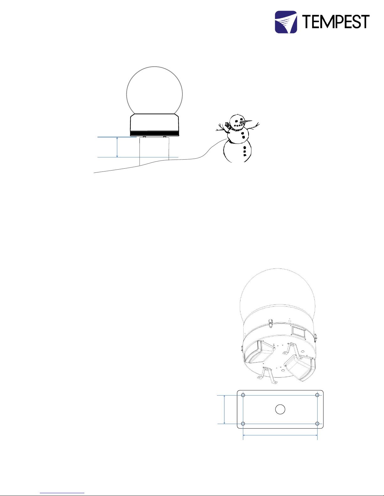
Planning
Snow clearance:
Enclosure must be powered 24/7/365.
Warning: This installation cannot be safely completed by 1 person.
Mounting –Tornado 1900-1950
Each Enclosure must be wall, floor or ceiling mounted with the two stainless steel
brackets provided.
Tempest Lighting recommends only stainless steel
mounting hardware for permanent installation
outdoors.
Floor, Wall or Ceiling Mounting
Use the two stainless steel mounting brackets provided
with the Tornado 1900/1950.
Fix the holes in the bracket feet to a secure structure using
3/8” [M10] stainless steel hardware (not supplied).
Pole Mounting
To mount to the top of a pole, fabricate a plate
with four 0.434”/11mm holes and weld to the top
of your pole. Use these dimensions:
MINIMUM
24”/60c
m
6”
[152mm]
Wiring Hole
15.5”
[394mm]

Cyclone Enclosure User Manual page 12
Pipe Mounting
Pipe Clamps
4900.MCT Pipe clamp, for pipes 1.5” (38mm) to 2” (50mm) OD.
Order TWO per enclosure.
4925.MCT Pipe clamp, for pipes 2” (50mm) to 2.5”/64mm OD.
Order TWO per enclosure.
Pipe Clamps mount to the enclosure base in the same
locations as the mounting brackets provided.
NOTE: Chesboro’ style half-couplers may be used for
temporary installations, but are not recommended for
permanent installs.
Mounting –Tornado 2000 and up
Each Enclosure must be mounted with FOUR points.
Tempest Lighting recommends only stainless steel mounting hardware.
The bolts attaching the enclosure to its shipping pallet are mounting bolts. Do not Discard.
All mountings must be made using the two Unistrut channels on the base of the enclosure.
Pipe Mounting
Pipe Clamps
4900.MCT Pipe clamp, for pipes 1.5” (38mm)
to 2” (50mm) OD. Order FOUR per enclosure.
4925.MCT Pipe clamp, for pipes 2” (50mm) to
2.5”/64mm OD. Order FOUR per enclosure.
Note: These parts are supplied with the
Tornado enclosure.
Cyclone Enclosure User Manual page 13
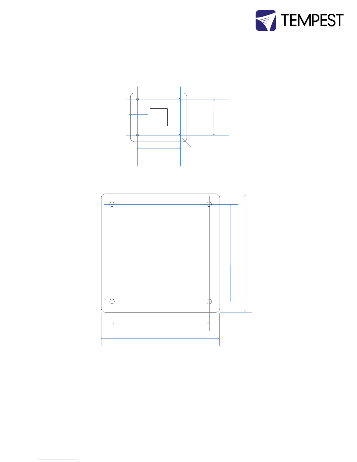
Mounting plate Guidelines
Use ¼” (6mm) or greater galvanized steel or stainless steel plate.
Do not obstruct wiring access.
Tornado 2000, 2200, 2300 Mounting Hole Pattern
Tornado 2400 Mounting Hole Pattern
10.0”
254mm
12.5”
317.5mm
Mounting holes
9/16”/13mm
Wiring Access
opening, 5” x 5”
(125 x 125mm)
12.25” /311mm
12.25” /311mm
15.00” /381mm
15.00” /381mm

Cyclone Enclosure User Manual page 14
Orientation Guidelines
Tornado 1900.xx
Tornado 1950.xx
Tornado 2000.xx
Tornado 2100.xx
Tornado 2200.xx
Tornado 2300.xx
Tornado 2000.xxH
Tornado 2100.xxH
Tornado 2200.xxH
Tornado 2300.xxH
Tornado 2000.xxV
Tornado 2100.xxV
Tornado 2200.xxV
Tornado 2300.xxV
Tornado 2400.xx
42”
(1067mm)
35.25”
(895mm)
34.25”
(870mm)
56.25”
(1429mm)
43.1”
(1092mm)
42”
(1067mm)
35.25”
(895mm)
34.25”
(870mm)
56.25”
(1429mm)
43.1”
(1092mm)
42”
(1067mm)
35.25”
(895mm)
34.25”
(870mm)
56.25”
(1429mm)
43.1”
(1092mm)
42”
(1067mm)
35.25”
(895mm)
34.25”
(870mm)
56.25”
(1429mm)
43.1”
(1092mm)

Cyclone Enclosure User Manual page 15
Drainage
For base up/globe down or horizontal operation, a small drainage hole will be drilled in the globe,
to permit any water draining through the enclosure to exit harmlessly.
This will normally be done at the factory, but if done on site, YOU MUST USE THE APPROPRIATE
TAPERED DRILL BIT, OBTAINABLE FREE OF CHARGE FROM TEMPEST LIGHTING. A standard drill
bit may crack the plexiglass globe. Tempest Lighting will not be responsible for such damage.
Horizontal Enclosures –be sure to replace the globe with the drainage hole at the lowest point
after relamping.
Note: A tapered drill bit is included with all Tornado 1900-1950 shipments. Weep holes must be
drilled on site as part of the installation process.
36”/914mm
Cyclone Enclosure User Manual page 16
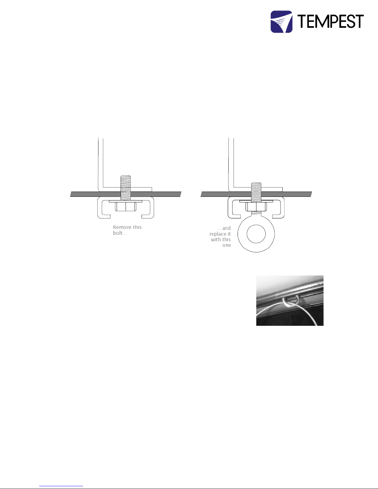
Installation above public Spaces
If the Tornado enclosure is to be installed above an area accessible to the public (eg a street or an
auditorium), some jurisdictions require a safety bond to be installed.
A stainless steel eyebolt is included with base-up and horizontal versions, and should be installed
as follows:
1. Remove one of the four bolts holding the Unistrut onto the enclosure base
2. Replace it with the eye bolt, washer and nut supplied, and screw down tight
Safety Bond
Use a suitably-rated steel wire rope, threaded through the eyebolt, and
attach securely to a structural member, in accordance with local safety
regulations.
Cyclone Enclosure User Manual page 17
3Wiring and Control
All electrical work must be carried out by a properly licensed electrician, in compliance with
local electrical standards. Failure to observe this point will void the factory warranty for the Tempest
Enclosure.
1Switch off power to the branch circuit, carefully following lockout and tag-out procedures. Failure to do so
could cause serious injury or death.
2You will need two electrical junction boxes, located within a short distance from the enclosure, one for power,
one for DMX control. Use outdoor-rated flexible conduit between the box and the enclosure.
3AC and control circuits must be wired in separate conduits.
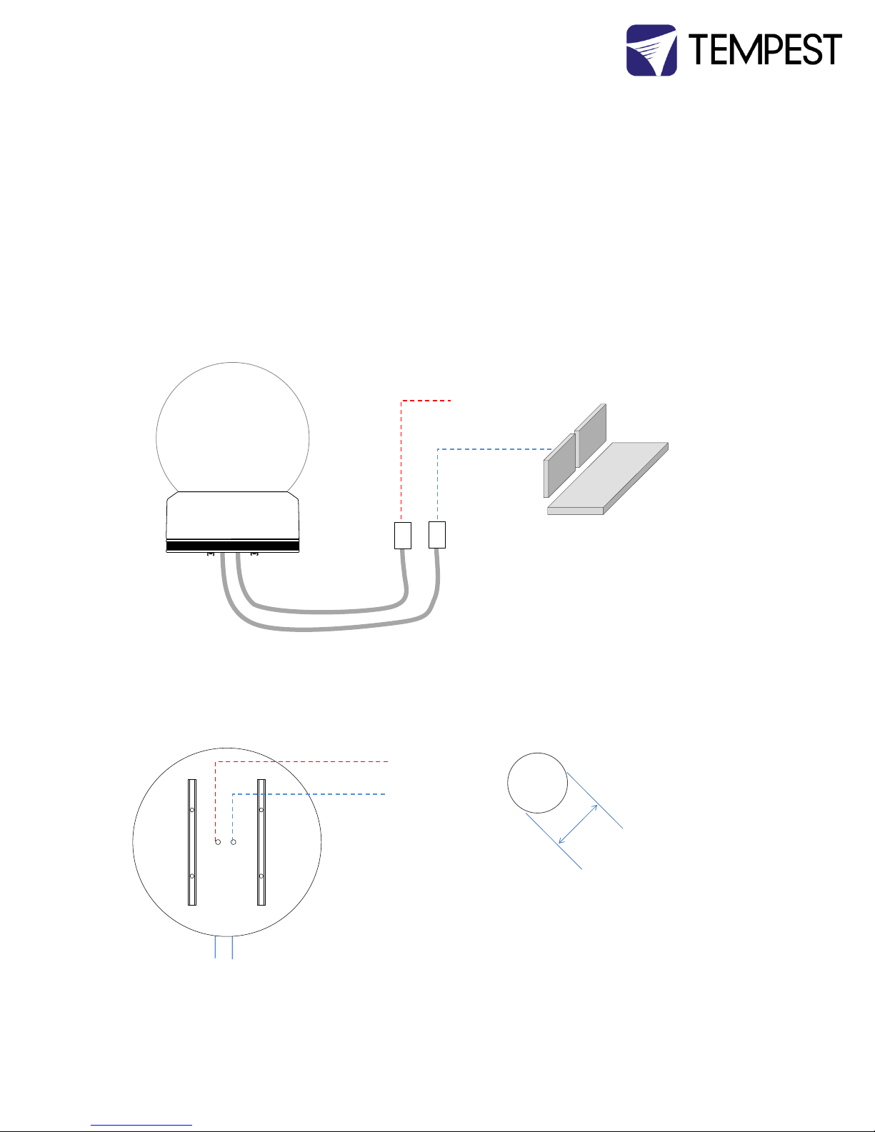
Conduit entry holes
Power and DMX conduit entries
The conduit entry holes accept US ½” conduit fittings, and
international 20-22mm (OD) conduit fittings.
For temporary installations, use a suitable cable and clamp in the
same openings.
AC
Power
DMX
Control
Flexible Conduit
120VAC, or
208VAC
or 230VAC
Lighting
Control
AC Power
DMX Control
Ø 0.875”
22.2mm

Cyclone Enclosure User Manual page 18
One or Two Power Circuits?
Single Feed Split Feed
Tempest enclosures may be wired on single or double line supplies. On a single feed, both
enclosure and luminaire are permanently on. With a double-line supply, you can switch off the
luminaire when not in use, while the enclosure continues to protect it 24/7.
Single Feed
Enclosure and luminaire are permanently on.
Enclosure and Luminaire must be rated for the same voltage.
Supply must be rated for luminaire current plus 150 watts.
Supply must be permanently ON.
Split feed
Enclosure power must be permanently ON.
Luminaire power may be switched off.
Enclosure power must be rated for 1150 watts.
Luminaire power must be rated for the luminaire (see luminaire manual).
Luminaire and enclosure power must be same voltage.
Either way, the enclosure must be powered 24/7, in order to protect the luminaire inside against
condensation and extremes of temperature.
Since the enclosure heater(s) never operate when the projector/fixture lamp is on, it is NOT
necessary to rate the power service for the SUM of the enclosure and the projector/light fixture.
IMPORTANT Tempest enclosures are supplied for either 120VAC 50/60Hz, or 208-240VAC,
50/60Hz operation. Tempest Lighting is not liable for damage or failure to
operate correctly due to connection to an inappropriate electrical supply.
ALL ELECTRICAL CONNECTIONS MUST BE UNDERTAKEN BY A QUALIFIED
ELECTRICIAN, IN COMPLIANCE WITH LOCAL NORMS AND STANDARDS.
1 21

Cyclone Enclosure User Manual page 19
Split Feed Connections
Note: wire colors may differ depending on applicable electrical standards. European wire colors are shown here.
IMPORTANT: MAKE SURE THAT TERMINAL SCREWS ARE FULLY BACKED OUT BEFORE INSERTING WIRES.
Common Feed Connection (factory default)
Enclosure and projector share the same electrical circuit.
Circuit must be powered ON 24/7.
Connect incoming power to the terminals labeled MAINS:
(E) Earth/Ground
(L) Live
(N) Neutral
E L N
Projector Supply
(split mode)
Enclosure Supply
(100-250VAC 50/60Hz)
Fan 1
Fan 2
Heater(s)
Projector
receptacle
Cut here for split
supply operation
Projector Supply
(split mode)
Enclosure Supply
(100-250VAC 50/60Hz)
Fan 1
Fan 2
Heater(s)
Projector
receptacle
Cut here for split
supply operation
1

Cyclone Enclosure User Manual page 20
4Digital Enclosure Control
DEC3.3TM with GoldilocksTM
DEC3.3TM –that’s Digital Enclosure Control, third Generation, revision 3 –is the brain of your
Tempest enclosure. It will maintain the internal environment in a comfortable temperature and
humidity range, and prevent condensation –the real killer of outdoor equipment. DEC3.3
monitors internal temperature, humidity and lamp current at all times, and uses this information
to control the enclosure’s lamp relay, fan(s) and heater(s). It can report back over the DMX cable,
using the RDM protocol (Remote Device Management) if desired.
From summer 2013 DEC is running Tempest’s new GoldilocksTM operating system (patents
pending). A completely new OS, Goldilocks analyzes temperature and humidity trends, targeting
and maintaining safe ranges, and acting to prevent condensation before it happens. Goldilocks is
also much more energy-efficient than previous generations, so your equipment is always in the
Goldilocks zone, and you save money too.
Lamp
Heater Fan RelayOn DMXTemp
ESC OK
This manual suits for next models
6
Table of contents
Other Tempest Lighting Equipment manuals

Popular Lighting Equipment manuals by other brands


Pentair
Pentair T40-F installation instructions

HAYASHI-REPIC
HAYASHI-REPIC LA-HDF5010RL instruction manual

Conrad
Conrad 1302513 operating instructions

Xiaomi
Xiaomi Mi Motion-Activated Night Light 2 user manual

LIVARNO home
LIVARNO home 373086-2204 Assembly, operating and safety instructions

DOTLUX
DOTLUX 5102 user manual