Templari KITA ARIA Manual
Installaon and maintenance manual
versione ARIA - ACQUA
vers. 24/01/19 G

Summary
1 Introducon ........................................................................................................... 6
1.1 General warnings.................................................................................................... 6
1.2 Recommended equipment ..................................................................................... 6
1.3 Series descripon ................................................................................................... 6
2 Read carefully before use ....................................................................................... 7
2.1 Important informaon ............................................................................................ 7
2.2 Proper use .............................................................................................................. 7
2.3 Rules and law provided .......................................................................................... 7
2.4 Energy saving.......................................................................................................... 7
3 Intended use of the heat pump ............................................................................... 7
3.1 Fields of work and safety devices ............................................................................ 7
3.2 Allowed operang zone .......................................................................................... 8
3.3 System structure with heat pump ........................................................................... 8
3.4 Components ........................................................................................................... 9
3.5 Mode of operaon ............................................................................................... 10
4 Equipment of supply ............................................................................................. 10
4.1 Main unit .............................................................................................................. 10
4.2 Name of the type and registraon number ........................................................... 10
4.3 Components scheme of external device of the heat pump KITA S/M/M3Phase
Templari® ............................................................................................................. 11
4.4 Components scheme of the external device of the heat pump KITA L33/L42/L66
Templari® ............................................................................................................. 12
5 Trasport ................................................................................................................ 13
6 Assembly and installaon ..................................................................................... 13
6.1 Oponal components on demand......................................................................... 13
6.2 Measures of the device ......................................................................................... 13
6.3 Free spaces for the assembly ................................................................................ 14
6.4 Choice of installaon place ................................................................................... 14
6.5 Assembly of the heat pump .................................................................................. 14
6.6
Preparaon of the condensate drain ........................................................................... 14
6.7 Alignment of the heat pump KITA Templari® ......................................................... 16
6.8 Probe installaon ................................................................................................. 16
7 Hydraulic connecons .......................................................................................... 16
7.1 Equipment control ................................................................................................ 16
7.2 Parcular Components ......................................................................................... 16
7.3 Installaon of hydraulic part ................................................................................. 17
7.4 Choice of the system scheme ................................................................................ 17
7.5 Scheme 1: Cooling/heang system ad DHW, with buer on return pipes. ............. 18
7.6 Scheme 2: Cooling/heang system, with buer on return pipes. .......................... 19
7.7 Scheme 3: System only DHW, with buer. ............................................................. 20
7.8 Scheme 4: Cooling/heang system and DHW with buer. ..................................... 21
7.9 Scheme 5: System with heat pump, solar thermic for heang and producon DHW,

with buer. ........................................................................................................... 22
7.10 Scheme 6: Cooling/heang system, with buer. ................................................... 23
7.11 Scheme 7: Cooling/heang system, DHW and integraon, with buer on return
pipes. ................................................................................................................... 24
8 Maintenance and cleaning .................................................................................... 25
8.1 Cleaning of the baery ......................................................................................... 25
8.2 Cleaning of the condensate drain .......................................................................... 25
8.3 Cleaning of hydraulic system side ......................................................................... 25
9 Electrical connecons ........................................................................................... 25
9.1 General informaon ............................................................................................. 25
9.2 Laying operaons ................................................................................................. 25
9.3 Supply .................................................................................................................. 26
9.4 Probes and remote panel ...................................................................................... 27
9.5 Terminal block wiring
KITA S/S Plus/M/M3Phase/ M3Phase plus ..................................... 27
9.6 Terminal block wiring single-phase models supply ................................................ 28
9.7
Terminal block wiring KITA L33/L42/L66 ........................................................................ 29
9.8 Terminal block wiring for three-phase models ...................................................... 30
9.9 Network wiring pLAN - “mul-KITA” ..................................................................... 30
10 Electronic board ................................................................................................... 31
10.1 Digital outputs ...................................................................................................... 31
10.2 Digital inputs ........................................................................................................ 31
10.3 Analogic outputs .................................................................................................. 31
10.4 Analogic inputs ..................................................................................................... 31
10.5 Wiring diagram KITA S/S Plus/M ........................................................................... 32
10.6 Wiring diagram KITA S 3Phase/S Plus 3Phase/M 3Phase / M Plus ......................... 33
10.7 Wiring diagram KITA L33/L42/L66 ......................................................................... 34
10.8 Internal wiring connecon diagram ...................................................................... 35
11 Inial operaon .................................................................................................... 36
11.1 Preliminary checks ................................................................................................ 36
11.2 Tesng and startup ............................................................................................... 36
12 Control terminal ................................................................................................... 38
12.1 Fixing of the panel ................................................................................................ 38
12.2 Unit control measures .......................................................................................... 38
12.3 Menu overview .................................................................................................... 39
12.4 Terminal buons .................................................................................................. 40
12.5 Display of the terminal ......................................................................................... 40
12.6 Main menu ........................................................................................................... 41
12.7 ON-OFF menu ....................................................................................................... 41
12.8 SETPOINT menu .................................................................................................... 41
12.9 Clock/metable menu .......................................................................................... 42
12.10 Input/Output menu .............................................................................................. 43
12.11 Alarms history menu ............................................................................................ 43
12.12 Board change menu .............................................................................................. 43
12.13 Assistance menu ................................................................................................... 43
13 Alarms .................................................................................................................. 48

13.1 Alarms resoluon ................................................................................................. 50
13.2 Nocaons ......................................................................................................... 51
14 Performances ....................................................................................................... 53
15 Declaraon of Conformity .................................................................................... 55
15.1 Declaraon of conformity KITA S/M/M3Phase ...................................................... 55
15.2 Declaraon of conformity KITA L/L42/L66 ............................................................. 56


6
www.templari.com
1 Introducon
This guide wants to give every informaon necessary to the
installaon and the correct funoning of the heat pump KITA
Templari®, from its put in acon during its whole life cycle . The
document is divided in chapters, in each of them there are general
informaon and mode of the operaons to be performed.
1.1 General warnings
• The choice and the use of the unit to serve the condioning
system have to be made by a competent sta according to
the current regulaons in place so to completely sasfy the
requests of the system.
• The installaon, the put in acon and the maintenance
have to be made by a competent sta able to evaluate the
possible presence of risk factors or malfuncon of the
machine.
• The unit is supplied complete with all the opons and the
operaons directly by the constructor, every manumission
of the fridge part or the soware aren’t allowed. Any
manumissions will make fall the operaons of the machine
and constructor’s responsibility.
• Periodic inspecons and a proper manintenance of the
heat pump KITA Templari®, can avoid damages to the unit
and possible costs for repairs.
• The warranty expires in case of installaon not complying
the specicaons.
• Keep this guide with the necessary diagrams in places
easily accessible.
• In case of malfuncon verify the error code on the control
panel, if necessary contact the installer; if necessary
require original spare parts.
• On the label of the heat pump KITA Templari® you can
nd all the informaon in relaon to current regulaons of
labeling, in parcular you can nd:
• Power to the machine in tension e frequency;
• Thermal power in heang and cooling schemes;
• Maximum power absorpon;
• Sound power level;
• Refrigerant used.
1.2 Recommended equipment
• Set of star and shear e screwdrivers;
• Nippers;
• Scissors;
• Set of wrenches or pipe wrench;
• Ladder;
• Hydraulic material for thread gasket;
• Electric equipment for connecons;
• Protecve gloves;
• Tester and current clamp;
1.3 Series descripon
The series of the heat pumps KITA Templari® presents monoblock
water heat engines for the producon of heang and cooling
thermal energy and the producon of domesc hot water with
the best technologies in the market.
The heat pump KITA Templari® is a series of machines full-
inverter that is with high performance components and widely
dimensioned to privilege the eciency of the machine. One
more parcularity is the implementaon of EVI technology
(Enhanced Vapour Injecon) in models KITA L, L42 and L66,
that broaden the eld of work and the power output to the
heat pump. The use of the gas R410A permits to reach high
performances and a low environmental impact. The presence of
two electronic valves, reversing valve, pressure transducers and
temperature sensors ensure, through the soware integrated in
the electronic board as microprocessor, the full funconality and
reliability of the machine in the dierent operaong regimes.
The control of the machine is done through a remote control that
permits to monitor the operaon of the machine and change
the temperature set of the water produced and the mode of
operaon (summer/winter).

7
www.templari.com
2 Read carefully before use
2.1 Important informaon
WARNINGS!
The pracce and the maintenance of the heat pump KITA
Templari®, are subject to legal systems of the countries where it
is used. According to the quanty of cooling uid it is necessary
to check e annotate the hermec seal of the heat pump at
regular intervals resorng to a qualied sta.
• During the transport it is possible to lt the heat pump no
more than 45° (in each direcon).
• The safety for the transport has to be removed before of
the put in acon.
• The aspiraon and unloading zone mustn’t be reduced or
covered.
• Respect specic building regulaons of each countries.
• For the installaon near the wall you have to consider degli
inuences due to building physiscs factors. In the area of
unload of the fan there must be no windows or doors.
• With the installaon near the wall the air ow in the
aspiraon and unloading zone can give a greater deposit
of impurity. The colder outside air has to go out so to not
increase the heat loss of bordering heated rooms.
• the dirt trap, not included but supplied on demand of
the customer, must be assembly on the heang return
upstream of the heat pump.
• The istallaon in niches or inner courtyards isn’t allowed,
because the cooled air accumulates on the ground and in
case of prolonged operaon it would be aspirated back by
the heat pump.
• The freezing limit can change following the climac region.
Respect the regulaons in force for the countries concerned.
• Respect the right-handed rotaon eld: in case of incorrect
wiring the start of the heat pump is hindered. The programmer
of the heat pump shows the relevant warning indicaon (to
correct the wiring).
• The operaon of the heat pump with too low temperature
system can cause its total block. Aer a prolonged power cut
you have to use the method of put in acon described below.
• Clean at regular intervals the dirt trap.
• Before opening the device cut o power to all the electrical
circuits.
• Works on the heat pump can be done only by authorized and
competent people of the customer care.
2.2 Proper use
The heat pump KITA Templari® is homologate just for the use
providede by the manufacturer. A dierent use moving away
from the provided one is considered not-compliant. The proper
use also includes the respect of the informaon included in
the relevant informave. It’s forbidden to make changes or
transformaons to the device.
2.3 Rules and law provided
This heat pump is desned, according to the arcle 1, chapter 2
k) of Direcve CE 2006/42/CE (Machines Direcve), to the use in
domesc and for this reason it is subject to the requirements of
the Direcve 2006/95/CE (Low power Direcve). In this way it
is arranged to be used by inexperienced people to heat shops,
oces and similar work environments, farms, hotels, small
hotels and similar or other residenal buildings.
In the planning and realizaon of the heat pump all the
correspondant CE direcves and DIN and VDE regulaons are be
respected (see Dichiarazione di conformità CE).
The electrical connecon of the heat pump KITA Templari® has to
be made following the current rules VDE, EN e CEI. Furthermore
the connecon condions of network operators of supply have
to be respected.
Concerning the heang system connecon you have to follow
current provisions.
People, in parcular kids, who on the base of physical, sensory
or mental abilies, or for inexperience or incompetence aren’t
able to use the device in safety, must’t use the device without a
responsible person’s supervision or guide.
Make sure kids don’t play with the device.
2.4 Energy saving
Using the heat pump KITA Templari® you contribute to the
respect of the environment. Condion for a energi saving
operaon mode is the correct disposion of heat sources and of
the system for the ulizaon of thermal energy.
Very important for the eciency of a heat pump is to keep the
dierence of temperature between the heang water and the
heat source as low as possible. For this reason we strongly
recommend an accurate sizing of the heat source and of the
heang system. A dierence of temperature higher than a degree
Kelvin (a °C) causes an increase of energy consumpon of 2,5 %
about. It is necessary to be careful, during the heang system
sizing, how special users are considered, as for example hot water
producon, and and how they are sized for low temperatures. An
underoor heang (surface heang) is the ideal to use a heat
pump thanks to ow temperatures (from 30 °C to 40 °C).
During the operaon it is important that impuries aren’t
accumulated in the heat exchangers, because the make increase
the dierence of temperature, worsening then the coecient of
performance.
3 Intended use of the heat
pump
3.1 Fields of work and safety devices
The heat pump KITA Templari® is enable to work at outdoor
temperature between -22°C (for the version S and M) and -32°C
(for the version L) and +46°C.
The machine allows following operaons elds relang to the
temperatures of the water produced:
• Heang: mimimum temperature 10°C, maximum
temperature 55°C
• Producon of domesc hot water: minimum temperature
35°C, maximum temperature 55°C
• Cooling: minimum temperature 7°C, maximum
temperature 40°C.
The heat pump KITA Templari® is equipped with a safety pressure
switch that stop the operaon of the machine when a pressure
8
www.templari.com
of 4,5 MPa (45 bar) is reached.
The product is provided with a ow sensor by volume (ow
switch). The ow switch ensures the stop of the machine if the
ow of water falls below the minimum threshold equal to 35-
40% of the nominal ow (1400 l/h).
The machine is equipped with an anfreeze system prevenng
the freezing of the water content in hydraulic pipes linked to the
heat pump in case of outdoor low temperature. The anfreezing
protecon, when working, keep the circulator is state of ON,
even if the heat pump is set in OFF. The machine stays in state of
“alert” when the protecon is acve because it could start if the
condions require it (even if it is in OFF)
WARNINGS!
Before of performing maintenance works on the machine make
sure to unplug the machine from the power supply.
• During the summer operaon an anfreezing protecon
prevents the freezing of the water in the system.
• Heat pump KITA Templari® is provided of a sonde that
controls the compressor discharge temperature. The
computer of the machine ensures that the discharge
temperature doesn’t exceed the maximum allowed value.
N O T E !
The device isn’t suitable to be used with a frequency converter.
If the machine is powered o (unplugged from the network)
for long periods, don’t stop oil heang procedure starng when
the machine is powered again. This procedure serves to prevent
compressor breakage.
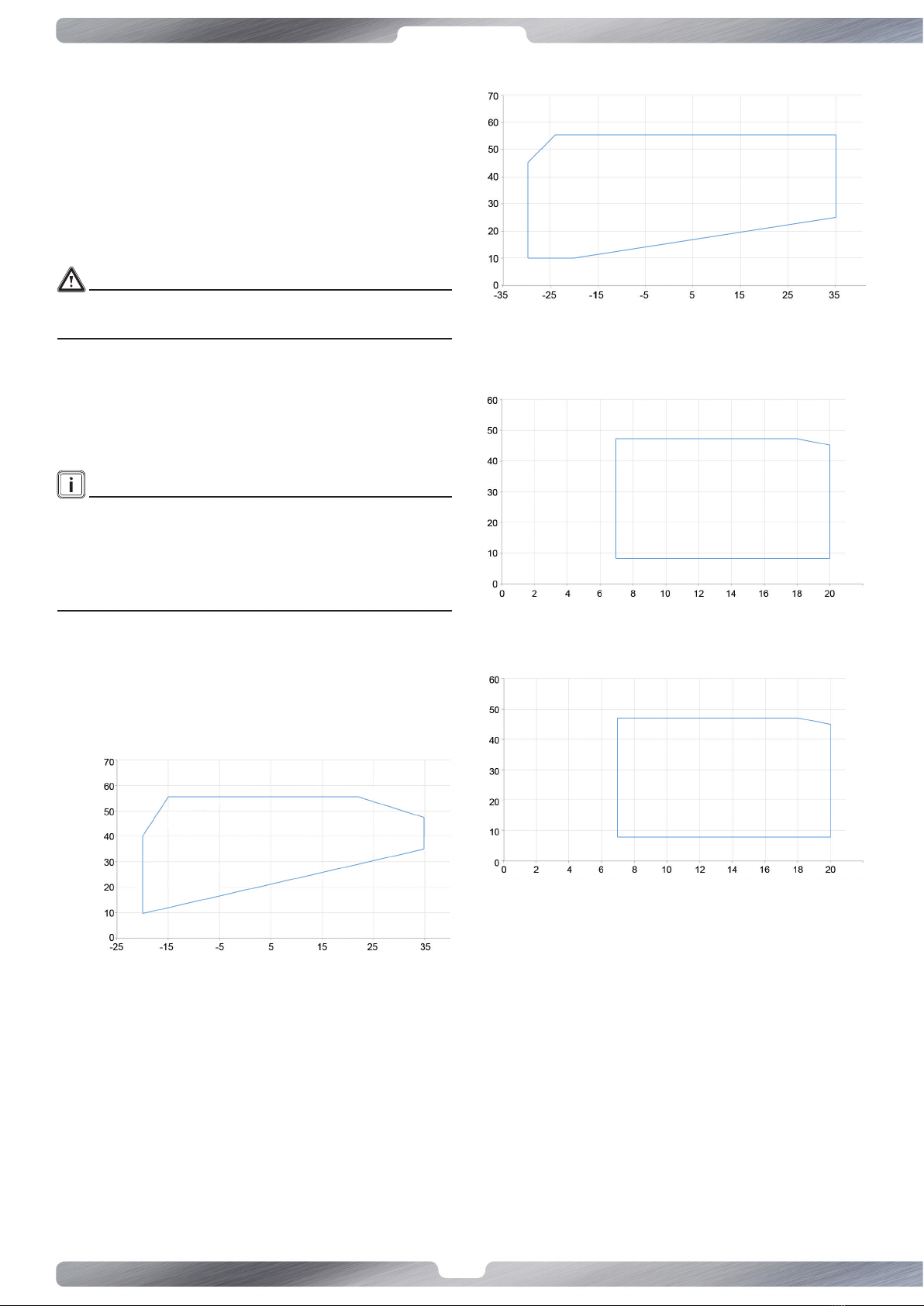
3.2 Allowed operang zone
KITA S - S 3phase - S plus - S plus 3phase / M
- M 3phase - M plus: heat pump
Water output temperature +/-2 [°C]
Outdoor air temperature +/-1 [°C]
KITA L - L42 - L66: heat pump
Water output temperature +/-2 [°C]
Outdoor air temperature [°C]
KITA S - S 3phase - S plus - S plus 3phase / M
- M 3phase - M plus: chiller
Outdoor air temperature +/-2 [°C]
Produced water temperature +/-1 [°C]
KITA L - L42 - L66: chiller
Water output temperature +/-2 [°C]
Water output temperature +/-1 [°C]
3.3 System structure with heat pump
The system with heat pump includes following components:
• Heat pump KITA Templari®;
• Control command of heat pump;
• Oponal hydraulic components, that can be required to
the manufacturer: a heang resistor for the condensate
drain, una a three-way valve for the combined system and
domesc hot water management, mesh lter, switching
relé operang with boiler integraon.
The control of machine funcons is totally done by command.
9
www.templari.com
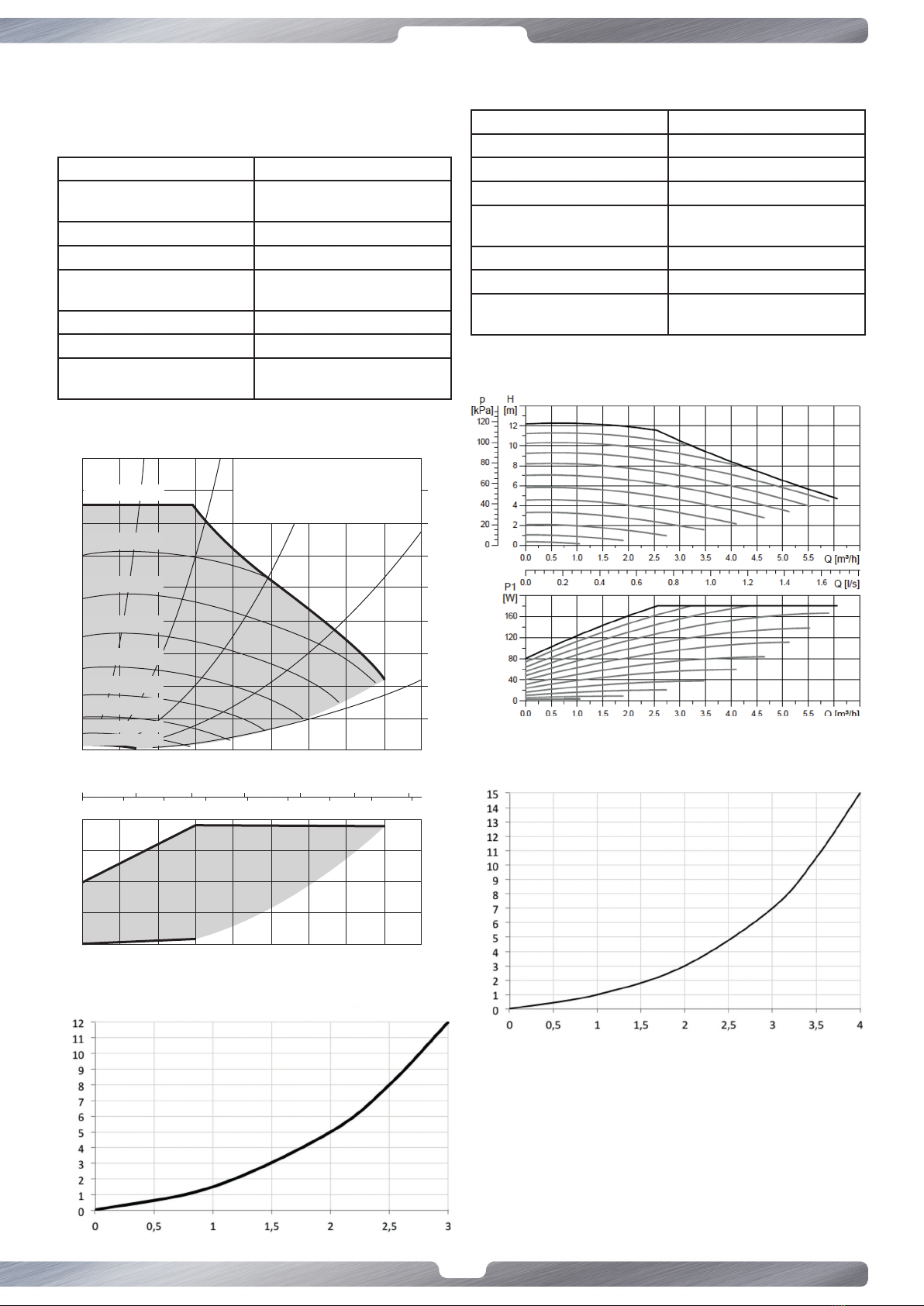
3.4 Components
KITA KITA S - S 3phase - S plus - S plus 3phase
/ M - M 3phase - M plus / L: Circulator Wilo
Yonos Para RS
Model Wilo Yonos Para RS 25/7.5
Voltage- frequenza di
alimentazione
1-230-V 50/60Hz
Indice di ecienza energeca A
Massima potenza assorbita 75 W
Massimo assorbimento di
corrente
0,6 A
Massima prevalenza 7,6 m
Minima pressione ingresso 0,5 bar
Temperatura producibile
dell’acqua
Da -10 a 95 °C
Characterisc curves of the circulator
max
max
80
70
60
50
40
30
20
10
0
8
7
6
5
4
3
2
1
0
p/kf
Q m3/h
Q m3/h
Q l/s
Q/lgpm
P1/W
H/m
4770/≤5PWM1
4270/15PWM1
3780/25PWM1
3280/35PWM1
2780/45PWM1
2280/55PWM1
1780/65PWM1
1290/75PWM1
790/85PWM1
0
0
0 2 4 6 8 10 12 14
0,2 0,4 0,6 0,8 1,0
0,5 1,0 1,5 2,0 2,5 3,0 3,5 4,0
0 0,5 1,0 1,5 2,0 2,5 3,0 3,5 4,0
Wilo - Yonos PARA RS
15/7.5 , 25/7.5 , 30/7,5
1-230 V - Rp ½, Rp 1, Rp ¼
n=1/min/ % PWM 1
60
40
20
0
Pressure loss in the plate heat exchanger
Water ow in heang [m³/h]
Loss of pressure [kPa]
KITA L42 - L66:
Circulator GRUNDFOS UPMXL
Model Grundfos UPMXL GEO 25-125
Tensione- supply frequency 1-230-V 50/60Hz
Energy eciency index A
Maximum power 180W
Maximum current
consumpon
1,4 A
Maximum head 12 m
Minimum input pressure 0,1 bar
Producible water
temperature
Da -10 a 95 °C
Characterisc curves of the circulator
Pressure loss in the plate heat exchanger
Water ow in heang [m³/h]
Loss of pressure [kPa]
10
www.templari.com
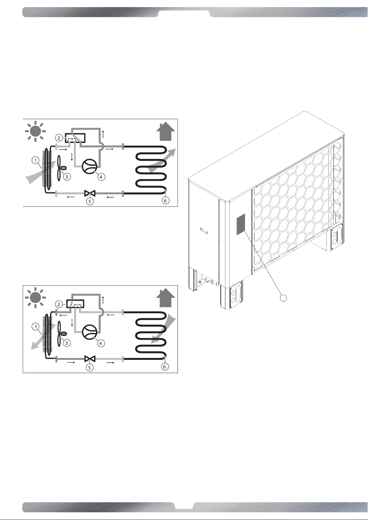
3.5 Mode of operaon
The heat pump can work in two ways, achievable through the
switching of the 4-way valve: as shown below, these modes are
heang and cooling/defrosng.
It’s also posssible to enter a special management module DHW
(domesc hot water) composed by relè, temperature sensors
and 3-way valves. Thanks to that the pump can manage the DHW
both in summer and in winter as a priority.
Heang mode
1 Evaporator
2 4-way valve
3 Fan
4 Compressor
5 Electronic expansion
valve
6 Plate heat exchanger
Cooling and defrosng mode
c
1 Evaporator
2 4-way valve
3 Fan
4 Compressor
5 Electronic expansion
valve
6 Plate heat exchanger
4 Equipment of supply
4.1 Main unit
The heat pump KITA Templari® is supplied in two units and it is
composed by the components showed in gure 1.
4.2 Name of the type and registraon
number
Model name and registraon number are on the plater (1) gure
1.
gure 1
1
11
www.templari.com
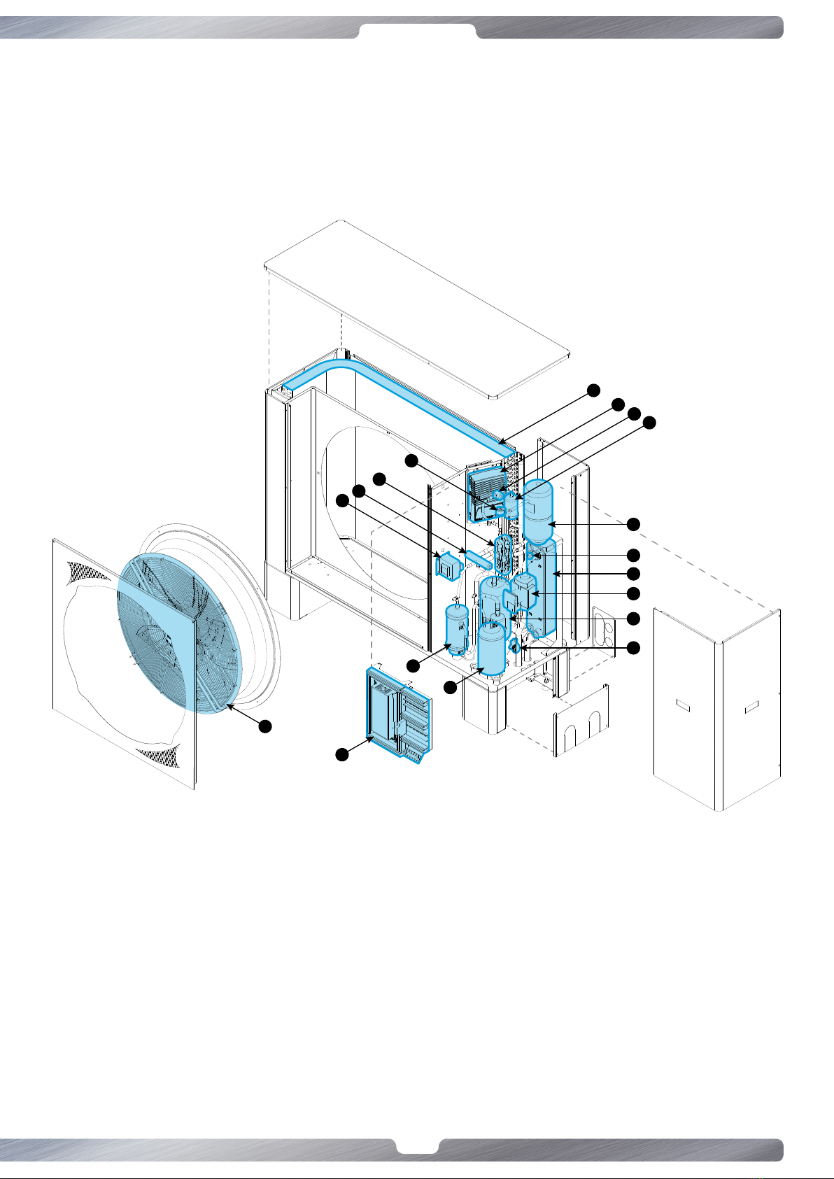
4.3 Components scheme of external device of the heat pump KITA S/M/M3Phase
Templari®
3
5
14
1
10
9
12
6
7
8
2
15
17
16
4
13
18
11
1 Vent valve
2 Inductance
3 Evaporaon/Condensaon baery
4 Compressor
5 Filter
6 Flowmeter
7 Liquid indicator
8 Inverter
9 Circulaon pump
The image is intended only to indicate the main internal components. The actual product may looks dierent.
10 Receiver of liquid
11 Electric board
12 Liquid separator
13 Oil separator
14 Heat plate exchanger
15 Check valves
16 Electronic expansion valve
17 4-way valve
18 Fan
12
www.templari.com
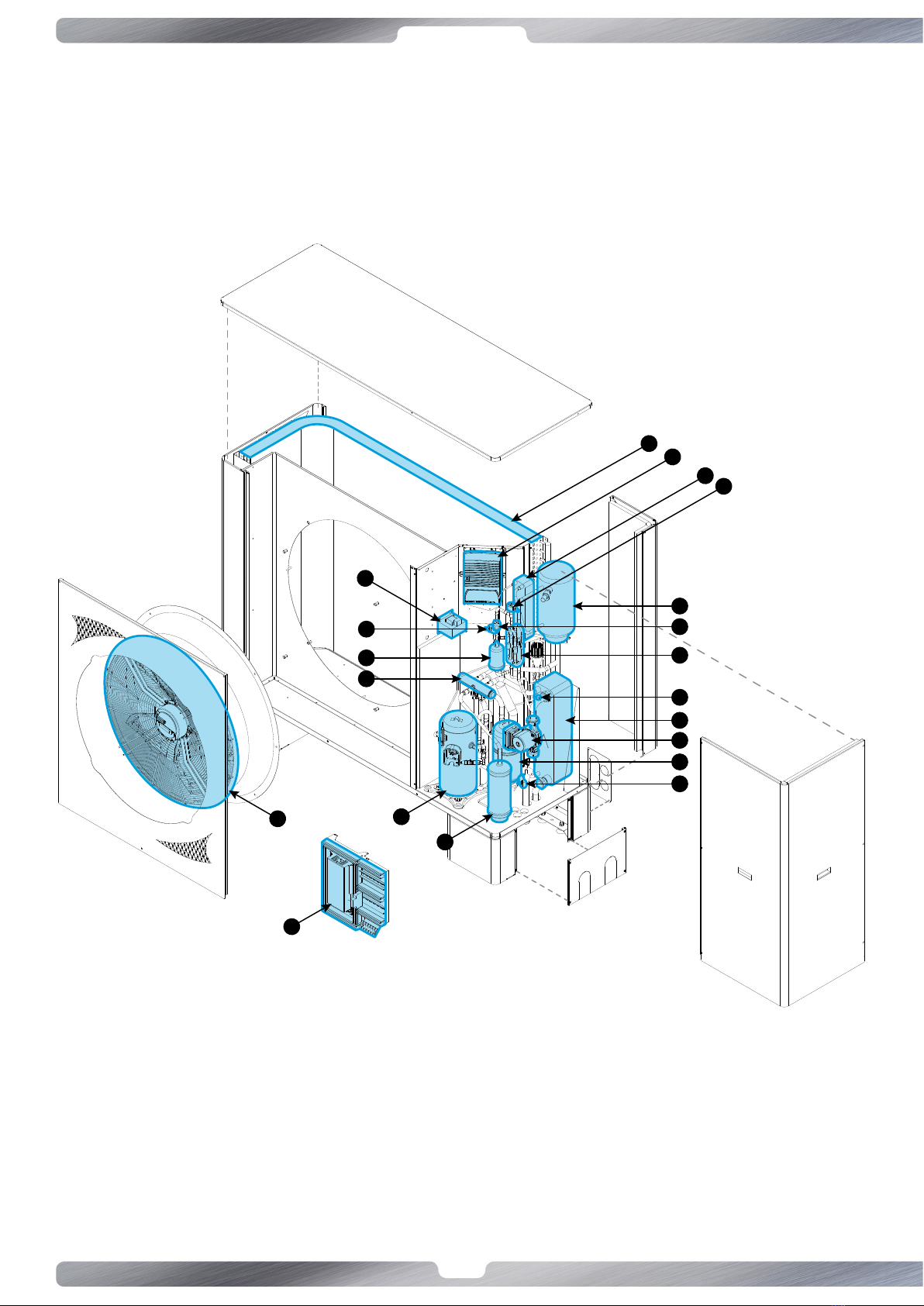
4.4 Components scheme of the external device of the heat pump KITA L33/L42/L66
Templari®
3
19
1
10
7
15
9
12
6
16
8
14
17
5
16
2
4
13
18
11
1 Vent valve
2 Inductance
3 Evaporaon/Condensaon baery
4 Compressor
5 Filter
6 Flowmeter
7 Liquid indicator
8 Inverter
9 Circulaon pump
10 Receiver of liquid
L’immagine ha il solo scopo di indicare i principali componen interni. Il prodoo può presentarsi diversamente.
11 Electric board
12 Liquid separator
13 Oil separator
14 Injecon plate exchanger
15 Check valves
16 Electronic expansion valve
17 4-way valve
18 Fan
19 Heat plate exchanger

13
www.templari.com
5 Trasport
WARNINGS!
Regardless of the type of transport, must never be inclined more
than 45°. Contrary you can have anomalies in the refrigerant
circuit in the next operaon. In severe cases this may have as a
consequence a failure inside.
The transport to the nal place of installaon should be done
on a pallelt. The heat pump KITA Templari® can be transported
using a forkli.
KITA S
KITA S PLUS
KITA S3Phase Kg. 180
KITA S3Phase Plus
KITA M
KITA M3Phase Kg. 220
KITA M3Phase Plus
KITA L33/L42/L66 Kg. 280
• Protect the sidewalls of the product coming into contact
with the forkli to prevent scratches and damages.
• Li the product only from the back and from the side of the
ngs.
• The liing of excessive weights can cause spinal injuries, for
example.
• Consider the weight of the product riported in the technical
data.
• In the transport of heavy loads, comply with the instrucons
and the provisions in force.
6 Assembly and installaon
6.1 Oponal components on demand
• Circulator for hydraulic system;
• Anvibraon for ground mounng support;
• Y lter;
• Anvibraon for piping.
6.2 Measures of the device
KITA S / S 3Phase / S Plus / S Plus 3Phase
271
210
76120
1406
908259550
R30
225 949 225 188 170 186186 170 188
1167
550
121
AB
CD
KITA M/M 3Phase/ M Plus
1591
1271
259 1012
225 1134 225
546
R30
122 91
121
221
282
188 188168
546
AB
CD
KITA L33/L42/L66
1516
325 1133 325
259 1257
1791
121
122
89
292
352
233 170 231
641
231 170 233
A
B
C
D
A: condensate drain
B: OUT
C: IN
D: cable passages

14
www.templari.com
6.3 Free spaces for the assembly
Distance Measures in millimeters
A >300
B >2500
C>300 KITA S >400 KITA M >500 KITA L
D>3000
E >1000
Respect the minimum distances menoned above to ensure a
sucient air ow and facilitate maintenance works.
• Verify there is asucient space for the installaon of the
hydraulic piping.
• If the product is installed in areas prone to heavy snowfalls,
verify the snow doesn’t accumulate around the product
and the minimum distances menoned above are
respected. If these condions can’t be sased, install then
an addional heat generator in the heang circuit.
6.4 Choice of installaon place
• Observe all the rules in force.
• Install the product outside the building.
• Don’t install the product:
- near a heat source,
- near ammable substances,
- near venlaon opening of conguous buildings,
- Below deciduous trees.
• For the installaon of the product observe:
- prevailing winds,
- noise of the fan and the compressor,
- opcal impression on the environment
• Avoid place where on the air outlet of the product there is
the eect of strong winds.
• Don’t orient the fan towards the near windows.
• If necessary, install noise-protecon system.
• Install the product on one of the following supports:
- Concrete pavement,
- T steal beem
- Concrete block.
• Don’t expose the product to dusty and corrosive air (e.g.
near rough roads).
• Don’t install the product near wells of air discharge.
• Prepare the laying of electrical cables.
• In places where there are snowfalls, install the heat pump
at least 25 cm from the ground to avoid clogging at the
inlet and drain zone.
6.5 Assembly of the heat pump
1. Before installing the product, observe the safety warnings
content in this manual and service manuals.
2. Assembly the product on steel beams, blocks of concrete
or with the help of a wall holder (accessory).
3. Verify that under the product water doesn’t accumulate
non si accumuli.
4. Verify that the oor in front of the product can well absorb
water to avoid ice formaon.
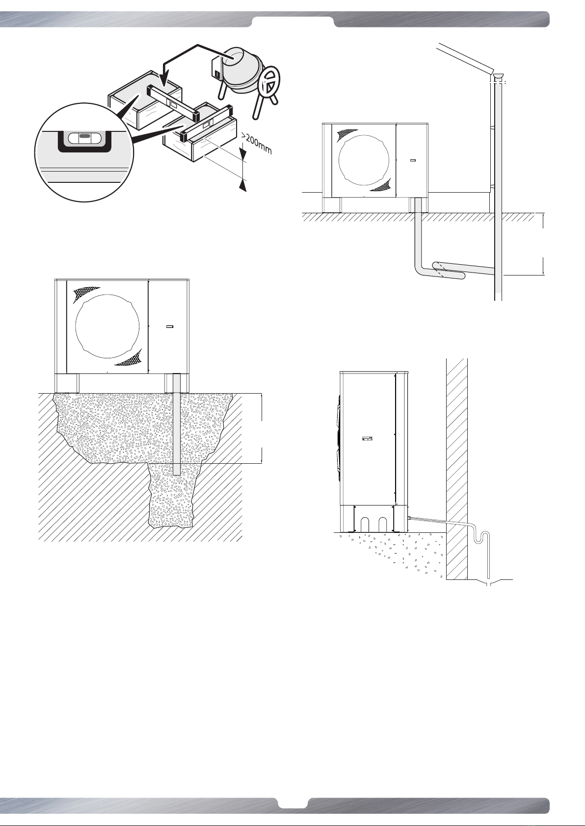
6.6
Preparaon of the condensate drain
The condensate is discharged in a centralized way from the back
of the heat pump KITA Templari®.
Prepare the condensate drain through a drain pipe or a gravel
bed.
WARNINGS!
The condensate frozen on the avenues can cause falls. Verify that
the condensate doesn’t ow on the avenues and can’t freeze on
them.
Frost proof
depth
min 200mm
Frost
proof
depth
Frost proof
depth
min 200mm
Frost
proof
depth
15
www.templari.com
• Example 2 condensate drain
• Example 3 condensate drain with condensate drain element
The condensaon water accumulated during the operaon must be
carried away without it can freeze. To ensure the correct oulow the
heat pump must be in a horizontal posion. The condensaon water
pipe must have a minimum diametre of 18mm and must ow in the
drain channel without it can freeze. Don’t discharge the condensate
directly into puricaon basins and moats. The aggressive fumes
and the condensaon pipe, if it isn’t protected against frost, can
cause irreparable damages to the evaporator.
In places where there are snowfalls, install the heat pump at least 25
cm from the oor to avoid clogging in the sucon and condensate
drain area.
• Preparaon of the base for condensate drain
• Example 1 condensate drain (it is advisable inter the
condensate drain pipe to avoid ice if you don’t buy the
oponal heang element for the condensate drain).
Frost proof
depth
min 200mm
Frost
proof
depth
Frost proof
depth
min 200mm
Frost
proof
depth
Frost proof
depth
min 200mm
Frost
proof
depth
16
www.templari.com
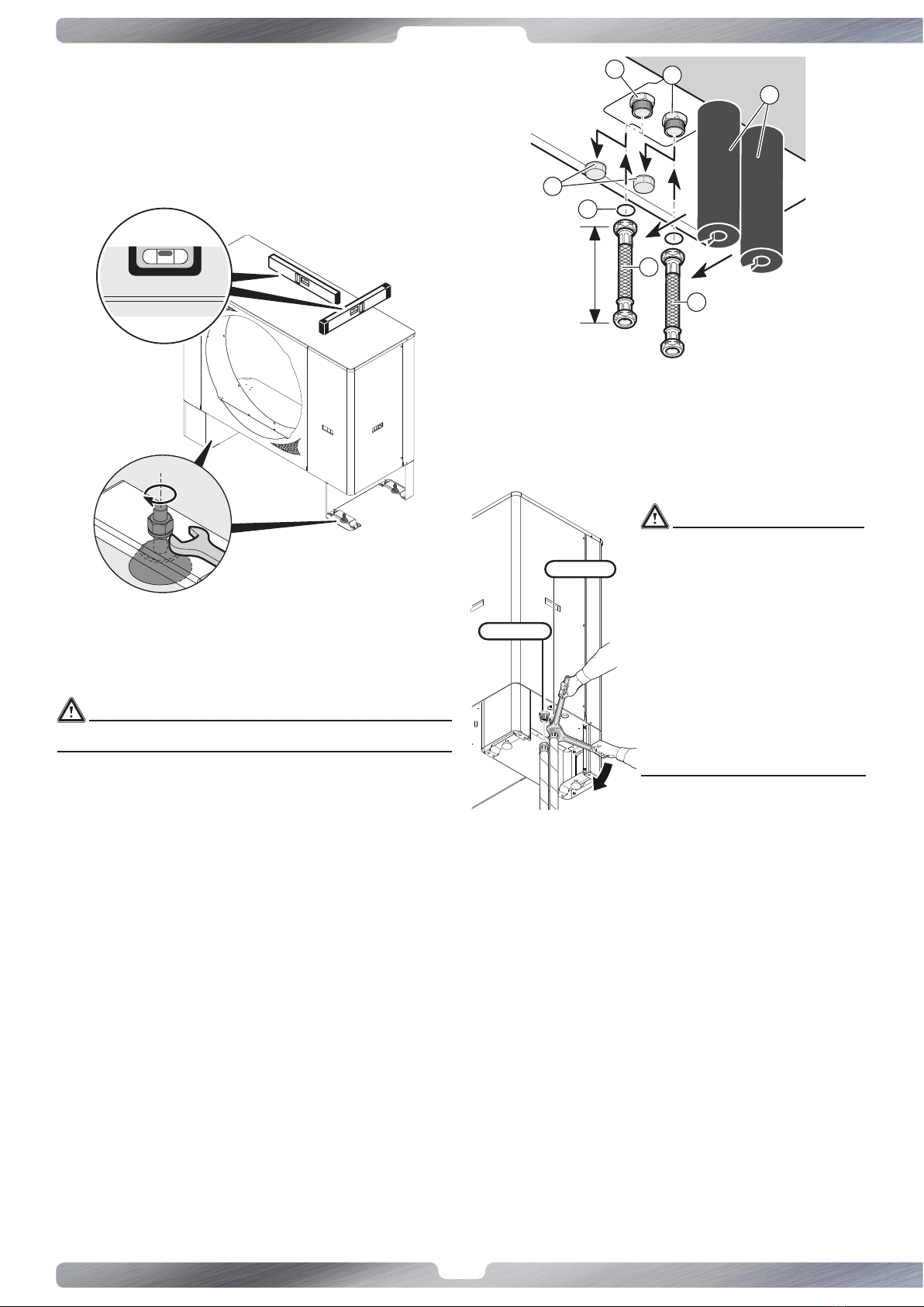
6.7 Alignment of the heat pump KITA
Templari®
Put horizontally the heat pump KITA Templari® so that the
condensate can ow. The product must be installed with
amorzed feet, purchased separately. The amorzed feet
increase the height of the product, facilitang the ow of
condensate and reducing vibraons.
6.8 Probe installaon
All probe used for the operaon of the plant must be installed
properly in the appropriate wells using a suitable thermal paste.
WARNINGS!
Installing the probes not in a proper way will voids the warranty.
7 Hydraulic connecons
7.1 Equipment control
1 Insulate wires (even underground) between product and
heang system con un isolamento resistente ai raggi UV e
alle alte temperature.
2 To avoid the transmission of vibraons on adjacent
buildings, use connecon lines to product with a lenght of
at least 0,75 m.
3 If the product isn’t installed in the hightest point of heang
circuit, install then in a suitable point some addional vent
valves.
4 Remove the covers (3) from the hydraulic ngs of the
circuit.
5 Install in the return of the heang circuit, between two
shut-o valves, an an-dirty lter to clean at regular
intervals.
6 Install a fexible pipe (1) e (6) (to be made on site) with a
gasket and a closing valve in the discharge ngs and the
riturn of the heang circuit of the heat pump.
7 Control the connecon seal.
5
4
7
3
2
2
6
0,75m min.
1 Flexible connecon tube in the
return of the heang to the building
(in place)
2 Gasket
3 Cover
4 Juncon (Ø 1”) return of the heang
to the building
5 Juncon (Ø 1”) heang supply to the
heat pump
6 Flexible connecon pipe in the
heang supply towards the heat
pump (in place)
7 Insulaon (in place)
WARNINGS!
If you use glycole, collect it on the
safety valve to avoid the polluon of
the environment.
The welding residues, slivers, hemp,
stucco, rust, dirt
and similar coming from the
pipelines can stand in the product
causing anomalies.
Rince thoroughtly the heat system
bifore of connecng the product to
remove possible residues!
Obligatory Y lter, contrary the
warranty will expire.
outlet
inlet
Operarate according to the rules in force, make sure the unit sia is
stably balances before of doing any operaons and always adopt
sempre protecon systems. The posioning indicaons shown
below are necessary for the correct operaon of the machine,
the maintenance and the operator protecon near the unit.
7.2 Parcular Components
The installer has to make the choice and the installaon of the
necessary components of the system, here below are listed
useful devices for the operaon of the machine:
• Shut-o valves at the entrance and exit of the circuit
allow maintenance operaons senza without draining the
system;
• Safety valve hydraulic side
• Thermometers and pressure gauges at the entrance and
exit of the main components ensure a beer monitoring
and facilitate the maintenance;
• Vent valves in the hightest points of the system ensure the
air vent from the circuit;
• Drain cocks in the boom of the system to facilitate the
emptying;
• Expansion vessel to keep the correct water pressure

17
www.templari.com
compensang thermal expansions, has to be sized
considering water total volumes in the system;
• The installaon of a Y lter is necessary.
WARNINGS!
Install hydraulic system side a safety valve.
7.3 Installaon of hydraulic part
• Thorough washing of the system with clean water lling
and emptying it many mes. This operaon allows to
riduce the number of maintenances and avoid damages to
exchangers and other components;
• Test of possible losses in the circuit;
• Insulate all the pipelines to reduce heat losses and avoid
the formaon of condensaon;
• Free up the service points like wells vents etc...;
• Verify that the quality of the water is suitable, contrary:
performance penalty, higher loading losses, possible
damages.
If there is the risk of water freezing in the system take the
following prevenve measures:
• Always powered machine for frost protecon;
• Mix water with ethylene glycol or propylene glycol
considering that the pressure losses increse and you have
to verufy the compability of all the hydraulic parts of all
these compounds;
• In case of long stops completely empty the system opening
all the cocks and pay aenon to avoid water stagnaon
points.
7.4 Choice of the system scheme
Make reference to the schemes shown in the following pages for
the realizaon of the hydraulic system according to your needs
and adapng it to the installaon context.
WARNINGS!
The buer, if on outlet pipe, must always comply with a minimum
quanty of liters according to the heat pump KITA used:
KITA S 200 Liters
KITA M 300 Liters
KITA L 500 Liters
WARNINGS!
If you have a pressure drop of more than 7 meters it is mandatory
to use an increased circulator.
WARNINGS!
Probe B2, when used, must always be placed in a buer mounted
on outlet pipe, never inlet.
WARNINGS!
The following diagrams are purely an example and Templars
s.r.l. will not be responsible for any reason for the plant made at
home. The plant shall be designed and manufactured exclusively
by qualied personnel.
WARNINGS!
For the producon of domesc hot water always use a puer-
type tank with rapid DHW producon or through outside
exchangers, contrary the warranty will be void.
WARNINGS!
it is extremely important that the puer dedicated to domesc
hot water producon, if used, is adequate for the power
produced by the heat pump.
Adequate puer must accumulate technical water, and not
domesc hot water.
pompa di calore ritorno
pompa di calore mandata
heat-pump
outlet DHW
technical
water heang
integraon
solar thermal
technical water
DHW
heat-pump
inlet
SUITABLE
BUFFER EXAMPLE*
heat-pump
outlet
DHW
plate heat
exchanger
instant
producon
DHW
technical water
technical water
heat-pump
inlet
SUITABLE
BUFFER EXAMPLE*
pompa di calore ritorno
pompa di calore mandata
DWH technical
water heang
integraon
heat-pump
outlet
heat-pump
inlet
DWH
NOT SUITABLE BUFFER EXAMPLE*
*
The image is intended only to indicate the main internal components and are
just examples.
Using a not suitable buer causes the compressor warranty to
vanish.
18
www.templari.com
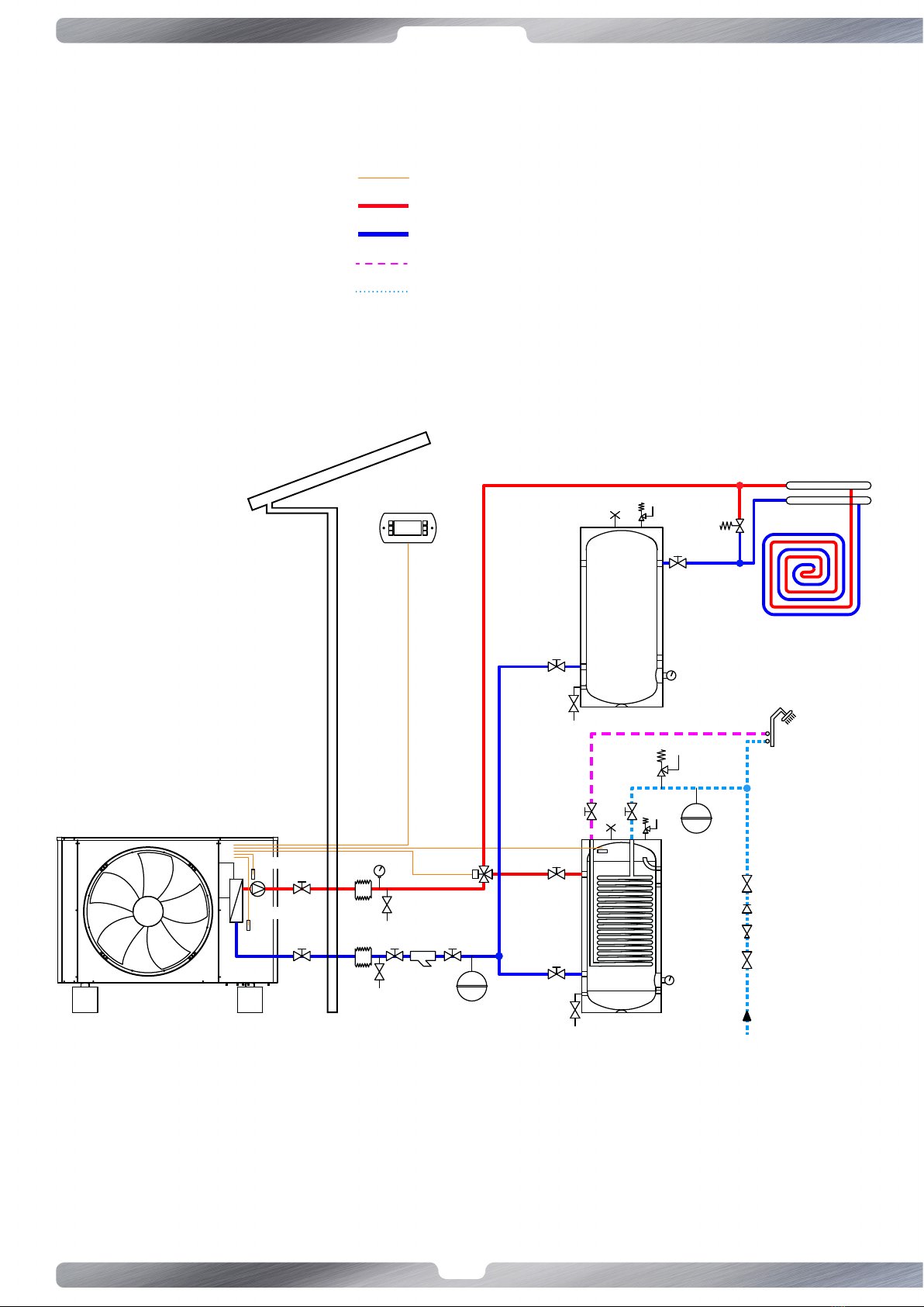
7.5 Scheme 1: Cooling/heang system ad DHW, with buer on return pipes.
In this conguraon, you MUST always keep open at least 25% of the collector area.
The bypass valve must have a broad scope to ensure the proper operaon of the heat pump when the radiant system allows lile
water passage.
PROBE B7
PROBE B4
GA
GA
RD
MA
USER INTERFACE
PROBE B3
COLLECTOR
FY
VE
UE
VE
RD
3W
SIGNAL CABLES
OUT
IN
GA
MA
RD
3W
VE
FY
UE
An�-vibra�on joint
Manometer
Drin tap
3 way valve
Expansion vessel
Y-filter
External unit
DHW
DW

19
www.templari.com
7.6 Scheme 2: Cooling/heang system, with buer on return pipes.
In this conguraon, you MUST always keep open at least 25% of the collector area.
The bypass valve must have a broad scope to ensure the proper operaon of the heat pump when the radiant system allows lile
water passage.
PROBE B7
PROBE B4
GA
GA
RD
MA
USER INTERFACE
COLLECTOR
FY
VE
RD
SIGNAL CABLES
OUT
IN
GA
MA
RD
VE
FY
UE
An�-vibra�on joint
Manometer
Drin tap
Expansion vessel
Y-filter
External unit
20
www.templari.com
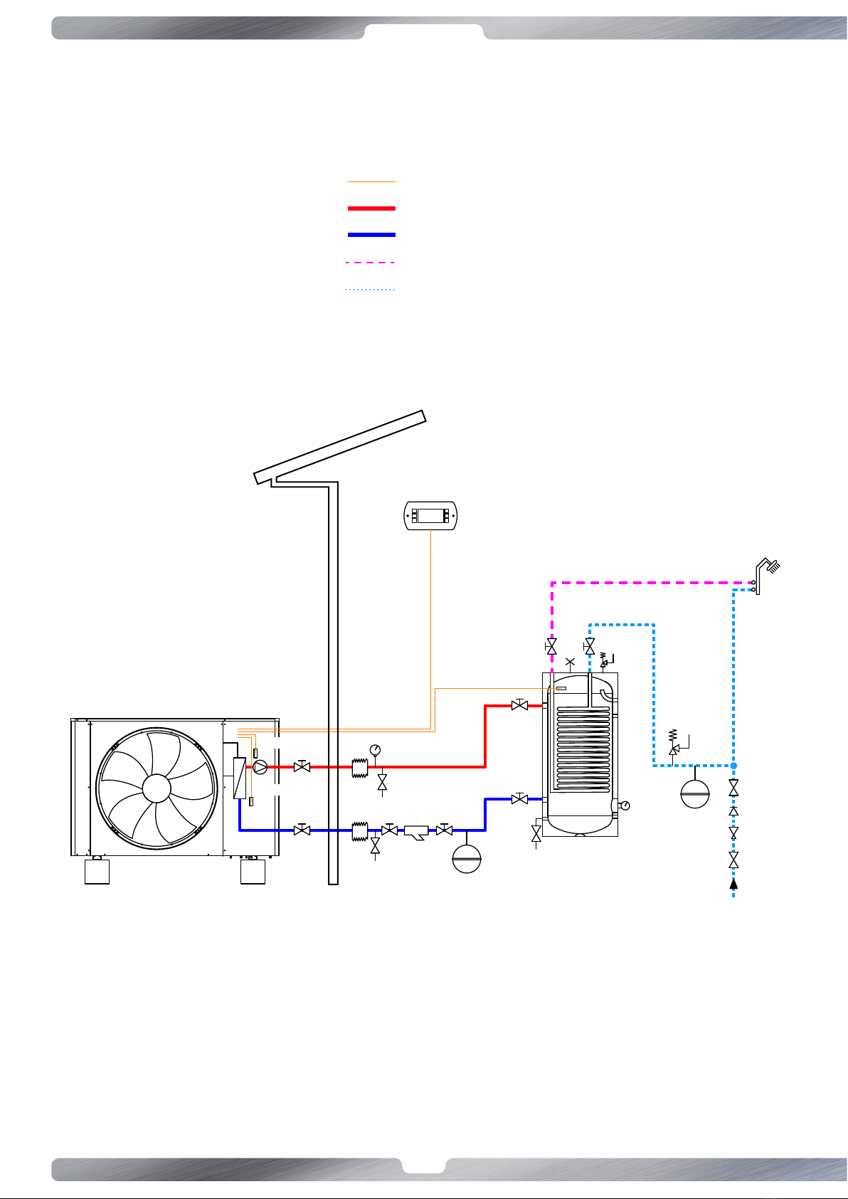
7.7 Scheme 3: System only DHW, with buer.
GA
GA
RD
UE
MA
USER INTERFACE
PROBE B3
FY
VE
VE
RD
PROBE B7
PROBE B4
SIGNAL CABLES
OUT
IN
GA
MA
RD
VE
FY
UE
An�-vibra�on joint
Manometer
Drin tap
Expansion vessel
Y-filter
External unit
DHW
DW
This manual suits for next models
11
Table of contents
Other Templari Heat Pump manuals


Popular Heat Pump manuals by other brands


Carrier
Carrier 50ZH Series Product data

ThermoPlus Air
ThermoPlus Air KHPE Series Installation, operation and maintenance manual

emmeti
emmeti MIRAI SMI 4.0 Installation and use manual

Nibe
Nibe F1345 Series operating manual

Kripsol
Kripsol Komfort RC2200 Installation instructions manual

Carrier
Carrier 50PEC09-18 Aquazone Installation, Start-Up and Service Instructions


