Temposonics GB Series User manual

Operation Manual
GB-Series SSI
Magnetostriktive Lineare Positionssensoren

2
Temposonics®GB-Series SSI
Operation Manual
Table of contents
1. Introduction.......................................................................................................................................................3
1.1 Purpose and use of this manual....................................................................................................................................................................3
1.2 Used symbols and warnings .........................................................................................................................................................................3
2. Safety instructions...............................................................................................................................................3
2.1 Intended use..................................................................................................................................................................................................3
2.2 Forseeable misuse.........................................................................................................................................................................................3
2.3 Installation, commissioning and operation....................................................................................................................................................4
2.4 Safety instructions for use in explosion-hazardous areas .............................................................................................................................4
2.5 Warranty........................................................................................................................................................................................................4
2.6 Return ...........................................................................................................................................................................................................4
3. Identification......................................................................................................................................................5
3.1 Order code Temposonics®GB ....................................................................................................................................................................... 5
3.2 Nameplate (example) ....................................................................................................................................................................................7
3.3 Approvals ......................................................................................................................................................................................................7
3.4 Scope of delivery........................................................................................................................................................................................... 7
4. Product description and commissioning .....................................................................................................................7
4.1 Functionality and system design ...................................................................................................................................................................7
4.2 Styles and installation of Temposonics®GB-J / GB-K / GB-N / GB-S............................................................................................................. 8
4.3 Styles and installation of Temposonics®GB-M / GB-T / GB-B .....................................................................................................................10
4.4 Magnet installation......................................................................................................................................................................................12
4.5 Change orientation of sensor electronics housing.......................................................................................................................................14
4.6 Replacement of base unit............................................................................................................................................................................14
4.7 Electrical connection ...................................................................................................................................................................................15
4.8 Frequently ordered accessories...................................................................................................................................................................16
5. Operation........................................................................................................................................................ 18
5.1 Getting started.............................................................................................................................................................................................18
5.2 Programming and configuration .................................................................................................................................................................18
6. Maintenance and troubleshooting .......................................................................................................................... 21
6.1 Error conditions, troubleshooting................................................................................................................................................................21
6.2 Maintenance................................................................................................................................................................................................21
6.3 Repair..........................................................................................................................................................................................................21
6.4 List of spare parts .......................................................................................................................................................................................21
6.5 Transport and storage ................................................................................................................................................................................. 21
7. Removal from service / dismantling........................................................................................................................ 21
8. Technical data.................................................................................................................................................. 22
8.1 Technical data GB-J / GB-K / GB-N / GB-S.................................................................................................................................................. 22
8.2 Technical data GB-M / GB-T ........................................................................................................................................................................ 23
9. Appendix ........................................................................................................................................................ 24
3
Temposonics® GB-Series SSI
Operation Manual
1. Introduction
1.1 Purpose and use of this manual
The content of this technical documentation and of its appendix is
intended to provide information on mounting, installation and com-
PLVVLRQLQJE\TXDOLğHGDXWRPDWLRQSHUVRQQHO1or instructed service
technicians who are familiar with the project planning and dealing
with Temposonics®sensors.
1.2 Used symbols and warnings
Warnings are intended for your personal safety and for avoidance of
damage to the described product or connected devices. In this doc-
umentation, safety information and warnings to avoid dangers that
might affect the life and health of operating or service personnel or
cause material damage are highlighted by the preceding pictogram,
ZKLFKLVGHğQHGEHORZ
2. Safety instructions
2.1 Intended use
7KLVSURGXFWPD\EHXVHGRQO\IRUWKHDSSOLFDWLRQVGHğQHGXQGHULWHP
1 and only in conjunction with the third-party devices and compo-
nents recommended or approved by MTS Sensors. As a prerequisite
of proper and safe operation, the product requires correct transport,
storage, mounting and commissioning and must be operated with
utmost care.
1. The sensor systems of all Temposonics®series are intended
exclusively for measurement tasks encountered in industrial,
commercial and laboratory applications. The sensors are
considered as system accessories and must be connected to
suitable evaluation electronics, e.g. a PLC, IPC, indicator or
other electronic control unit.
Before starting the operation of Temposonics®position sensors read
this documentation thoroughly and follow the safety information.
Keep the manual for future reference!
Symbol Meaning
This symbol is used to point to situations
that may lead to material damage, but not to
personal injury.
NOTICE
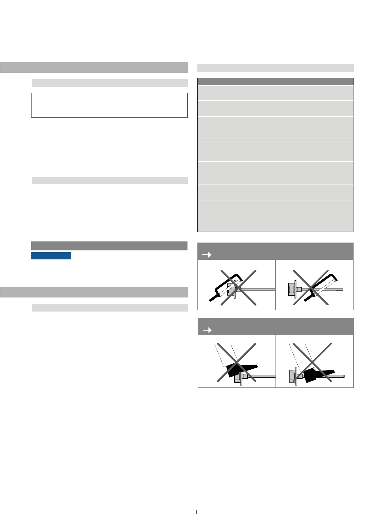
2.2 Forseeable misuse
Do not step on the sensor.
The sensor might be damaged.
Do not alter the sensor afterwards.
The sensor might be damaged.
1/ 7KHWHUPTXDOLğHGWHFKQLFDOSHUVRQQHOFKDUDFWHUL]HVSHUVRQVZKR
• are familiar with the safety concepts of automation technology applicable to the
particular project,
• DUHFRPSHWHQWLQWKHğHOGRIHOHFWURPDJQHWLFFRPSDWLELOLW\(0&
• have received adequate training for commissioning and service operations
• are familiar with the operation of the device and know the information required for
correct operation provided in the product documentation.
Foreseeable misuse Consequence
Wrong sensor connection The sensor will not work
properly or can be damaged
Operate the sensor out of the
operating temperature range
No signal output
The sensor can be damaged
Power supply is out of the
defined range
Signal output is wrong /
no signal output /
the sensor can be damaged
Position measurement is
influenced by an external
magnetic field
Signal output is wrong
Cables are damaged
Short circuit – the sensor can
be destroyed / sensor does not
respond
Spacers are missing /
installed in wrong order Error in position measurement
Wrong connection
of ground / shield
Signal output is disturbed
The electronics can be damaged
Use of a magnet that is not
certified by MTS Sensors Error in position measurement

4
Temposonics®GB-Series SSI
Operation Manual
2.3 Installation, commissioning and operation
The position sensors must be used only in technically safe condition.
To maintain this condition and to ensure safe operation, installation,
FRQQHFWLRQDQGVHUYLFHZRUNVKRXOGRQO\EHSHUIRUPHGE\TXDOLğHG
technical personnel.
If danger of injury to persons or of damage to operating equipment is
caused by sensor failure or malfunction, additional safety measures
VXFKDVSODXVLELOLW\FKHFNVOLPLWVZLWFKHV(0(5*(1&<6723V\V-
tems, protective devices etc. are required. In the event of trouble, shut
down the sensor and protect it against accidental operation.
Safety instructions for commissioning
To maintain the sensor's operability, it is mandatory to follow the
instructions given below.
1. Protect the sensor against mechanical damage during installation
and operation.
2. Do not open or dismantle the sensor.
3. Connect the sensor very carefully and pay attention to the polarity
of connections and power supply.
4. Use only approved power supplies.
5. ,WLVLQGLVSHQVDEOHWRHQVXUHWKDWWKHVSHFLğHGSHUPLVVLEOHOLPLW
values of the sensor for operating voltage, environmental condi-
tions, etc. are met.
6. Check the function of the sensor regularly and provide documenta-
tion of the checks.
7. %HIRUHDSSO\LQJSRZHUHQVXUHWKDWQRERG\łVVDIHW\LVMHRSDUGL]HG
by starting machines.
2.4 Safety instructions for use in explosion-hazardous areas
7KHVHQVRULVQRWVXLWDEOHIRURSHUDWLRQLQH[SORVLRQKD]DUGRXVDUHDV
2/ See also applicable MTS Sensors terms of sales and delivery on
www.mtssensors.com
2.5 Warranty
MTS Sensors grants a warranty period for the Temposonics®posi-
tion sensors and supplied accessories relating to material defects and
faults that occur despite correct use in accordance with the intended
application 2. The MTS Sensors obligation is limited to repair or re-
SODFHPHQWRIDQ\GHIHFWLYHSDUWRIWKHXQLW1RZDUUDQW\FDQEHSURYLG-
ed for defects that are due to improper use or above average stress of
the product, as well as for wear parts.
Under no circumstances will MTS Sensors accept liability in the event
of offense against the warranty rules, no matter if these have been as-
sured or expected, even in case of fault or negligence of the company.
MTS Sensors explicitly excludes any further warranties.
1HLWKHUWKHFRPSDQ\łVUHSUHVHQWDWLYHVDJHQWVGHDOHUVQRUHPSOR\HHV
DUHDXWKRUL]HGWRLQFUHDVHRUFKDQJHWKHVFRSHRIZDUUDQW\
2.6 Return
For diagnostic purposes, the sensor can be returned to MTS Sensors
or a repair facility explicitly authorized by MTS Sensors. Any shipment
cost is the responsibility of the sender 2. For a corresponding form,
see chapter “9. Appendix” on page 24.

5
Temposonics® GB-Series SSI
Operation Manual
3. ,GHQWLğFDWLRQ
3. rder code Temposonics®GB
Trademarks and trade names mentioned in this document are those of their
respective owners.
d onnector type
4 0PDOHFRQQHFWRUSLQ
1RWHWKHRSHUDWLQJWHPSHUDWXUHRIWKHFRQQHFWRU
0PDOHFRQQHFWRUSLQ
1RWHWKHRSHUDWLQJWHPSHUDWXUHRIWKHFRQQHFWRU
+Ľ+ĽP4;;P385FDEOH
SDUWQR
+Ľ+ĽIW4 ft 385FDEOH
SDUWQR
1RWHWKHRSHUDWLQJWHPSHUDWXUHRIWKHFDEOH
T 7Ľ7ĽP4;;P7HĠRQ®cable
SDUWQR
7Ľ7ĽIW4 ft 7HĠRQ®cable
SDUWQR
9Ľ9ĽP4 m Silicone cable
SDUWQR
9Ľ9ĽIW4 ft Silicone cable
SDUWQR
e perating oltage
9'&ũ
a Sensor model
G B 5RG
3/ 7KHVHQVRULQVWDLQOHVVVWHHO$,6,/LVRQO\DYDLODEOHZLWKIROORZLQJRSWLRQ
SũĽŹ&ũĽŹ)
*/ 1RQVWDQGDUGVWURNHOHQJWKVDUHDYDLODEOHPXVWEHHQFRGHGLQPPLQLQFUHPHQWV
4/ (QFRGHLQPHWHUVLIXVLQJPHWULFVWURNHOHQJWK(QFRGHLQIHHWLIXVLQJ86FXVWRPDU\
stroke length
12 3 45679111 12 1314151617 19 2 21
G B S
a c d e f gh
.
c Stroe length
25325 mm
ĽLQ
Standard stroe length mm rdering steps
25 5 mm 5 mm
5 75 mm 1 mm
751 mm 25 mm
125 mm 5 mm
25325 mm 1 mm
Standard stroe length in. rdering steps
1 2 in. .2 in.
2 3 in. .5 in.
3 4 in. 1. in.
41 in. 2. in.
ĽLQ 4. in.
esign
*%ZLWKWKUHDGHGĠDQJH
B%DVHXQLWIRUWKUHDGHGĠDQJHVŊ0ʼnDQGŊ7ʼnUHSODFHPHQWRQO\
7KUHDGHGĠDQJHZLWKĠDWIDFH0ūJ
T7KUHDGHGĠDQJHZLWKUDLVHGIDFHŧ81)$
*%ZLWKSUHVVXUHğWĠDQJH
ousing material stainless steel .435 ISI 33,
rod material stainless steel .43 ISI 34
3UHVVXUHğWĠDQJHPPPPURGEDU
ousing material stainless steel .435 ISI 33,
rod material stainless steel .436 .43 ISI 34
3UHVVXUHğWĠDQJHPPPPURGZLWKEXVKLQJ
on rod end
ousing material stainless steel .444 ISI 36,
rod material stainless steel .444 ISI 363
3UHVVXUHğWĠDQJHPPPPURG
Sousing material stainless steel .435 ISI 33,
rod material stainless steel .436 .43 ISI 34
3UHVVXUHğWĠDQJHPPPPURG fSee next page
gh

6
Temposonics®GB-Series SSI
Operation Manual
g perating temperature
ũĽŹ&ũĽŹ)
SũĽŹ&ũĽŹ)
h rogramming
ia cable
f utput
S 4 5 6
Synchronous Serial Interface
ata length ox no. 4
25 bit
224 bit
utput format ox no. 5
Binary
G*UD\
Resolution ox no. 6
.5 mm
2.1 mm
3.5 mm
4.1 mm
5.2 mm
iltering performance ox no.
1RğOWHU
2$YHUDJHğOWHU
3$YHUDJHğOWHU
4$YHUDJHğOWHU
erformance ox no. ,
Measuring direction forward, asynchronous measurement
Measuring direction reverse, asynchronous measurement
2 Measuring direction forward, synchronous measurement
3Measuring direction reverse, synchronous measurement
7
Temposonics® GB-Series SSI
Operation Manual
3.2 ameplate example
3.3 pproals
&(FHUWLğFDWLRQ
4. roduct description and commissioning
3.4 Scope of deliery
GB- GB- GB- GB-S(rod sensor with pressure fit flange)
Sensor
O-ring
ack-up ring
GB- GB-T (rod sensor with threaded flange)
Sensor
O-ring
GB-B (base unit for rod sensor with threaded flange)
Sensor
4. unctionality and system design
roduct designation
Position sensor Temposonics®*%6HULHV
Sensor model
Temposonics®*%-*%.*%1*%6*%0*%7VHQVRUURG
Stroke length 25PPĽLQ
utput signal
SSI
pplication
Temposonics®position sensors are used for measurement and con-
YHUVLRQRIWKHOHQJWKSRVLWLRQYDULDEOHLQWKHğHOGVRIDXWRPDWHG
systems and mechanical engineering.
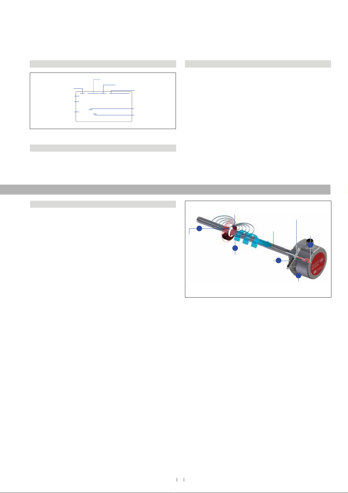
rinciple of operation and system construction
The absolute, linear position sensors provided by MTS Sensors
rely on the companys proprietary Temposonics®magnetostrictive
technology, which can determine position with a high level of
SUHFLVLRQDQGUREXVWQHVV(DFK7HPSRVRQLFV®position sensor
consists of a ferromagnetic waveguide, a position magnet, a strain
pulse converter and supporting electronics. The magnet, connected
WRWKHREMHFWLQPRWLRQLQWKHDSSOLFDWLRQJHQHUDWHVDPDJQHWLFğHOG
at its location on the waveguide. A short current pulse is applied to
WKHZDYHJXLGH7KLVFUHDWHVDPRPHQWDU\UDGLDOPDJQHWLFğHOGDQG
torsional strain on the waveguide. The momentary interaction of the
PDJQHWLFğHOGVUHOHDVHVDWRUVLRQDOVWUDLQSXOVHWKDWSURSDJDWHVWKH
length of the waveguide. hen the ultrasonic wave reaches the end of
the waveguide it is converted into an electrical signal. Since the speed
of the ultrasonic wave in the waveguide is precisely known, the time
required to receive the return signal can be converted into a linear
position measurement with both high accuracy and repeatability.
odular mechanical and electronic construction
The sensor rod protects the inner sensor element.
The sensor electronics housing, a rugged stainless steel
construction, contains the complete electronic interface with active
signal conditioning.
The external position magnet is a permanent magnet. Mounted on
the mobile machine part, it travels along the sensor rod and triggers
the measurement through the sensor rod wall.
The sensor can be directly connected to a control system. Its
electronics generates a position signal output proportional to the
start and end of the active measuring range.
Fig. 1: Example of a nameplate of a GB-S sensor
Fig. 2: 7LPHRIĠLJKWEDVHGPDJQHWRVWULFWLYHSRVLWLRQVHQVLQJSULQFLSOH
5
Sensing element
(Waveguide)
Position magnet (Magnetic field) Torsional strain
pulse converter
4
Current pulse
generates
magnetic field
Interaction with
position magnet
field generates
torsional strain
pulse Torsional strain
pulse propagates
Strain pulse
detected by
converter
Time-of-flight converted
into position
1
2
3
GBS0850MD701S2G5100SC
0.02 mm / 24 Bit gray
Grd.: 2807.46 m/s
FNr. 1601 0376
1601037616010376160103761601
Sensor model
Stroke length (e.g. 850 mm)
Connection type
Output
version
Part no.
Output
Production no. Week
Year
Temposonics®GB-Series SSI
Operation Manual
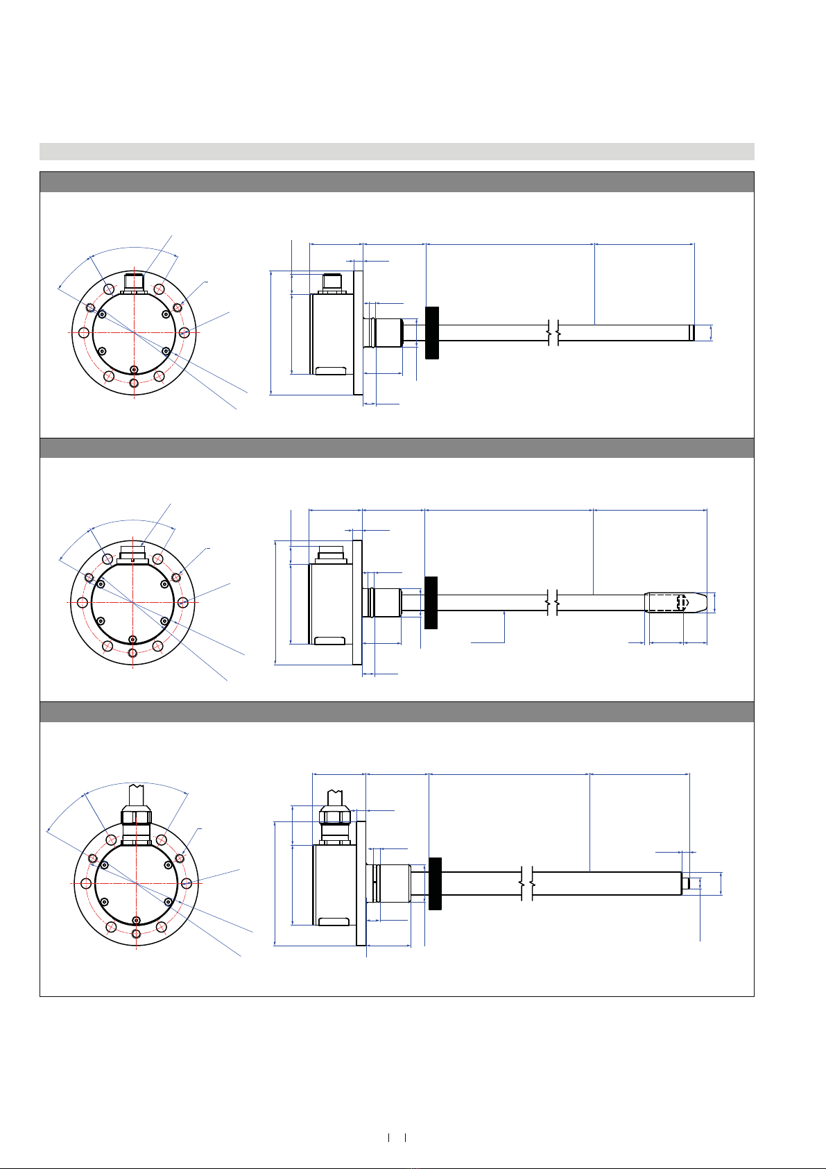
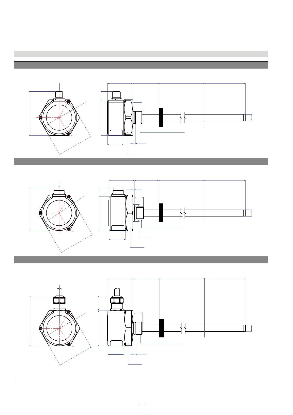
Fig. 3: 7HPSRVRQLFV®GB-N / GB-S / GB-K / GB-J
4.2 Styles and installation of Temposonics®GB- GB- GB- GB-S(rod sensor with pressure fit flange)
GB- GB-S, example With 2 connector
agnet
1 .13
.39 .1
79 3.11
13
.51
25
1
1 f7
6
.24
51
2.1
M6 3
64 2.52
6.5
.26
6
3
53 2.9
Stroe length
25 325
1 12
ull zone
4
1.57
ead zone
63.5
2.5
.1
.32
4.1
.16
2 connector
Sensor electronics
housing
34
1.34
GB-, example With 6 connector
agnet
79 3.11
1 f7
11.3
.44
51
2.1
6
.24
25
1
1
.39
3
.12
22
.7
15
.59
12. .1
.5 .4
M6 3
64 2.52
6.5
.26
6
3
53 2.9
Sensor electronics
housing
34
1.34
Stroe length
25 325
1 12
ull zone
4
1.57
ead zone
7.5
3.1
.1
.32
4.1
.16
6 connector
GB-, example With cale outlet
agnet
25
1
79 3.11
51
2.1
6
.24
M6 3
6.5
.26
64 2.52
6
3
53 2.9
Stroe length
25 325
112
ull zone
4
1.57
ead zone
73.5
2.9
12.7 .13
.5 .1
6.2
.244
4
.16
4.1
.16
.5
.31
25
.9
Sensor electronics
housing
34
1.34
21 f6
&RQWUROOLQJGHVLJQGLPHQVLRQVDUHLQPLOOLPHWHUVDQGPHDVXUHPHQWVLQDUHLQLQFKHV
9
Temposonics® GB-Series SSI
Operation Manual
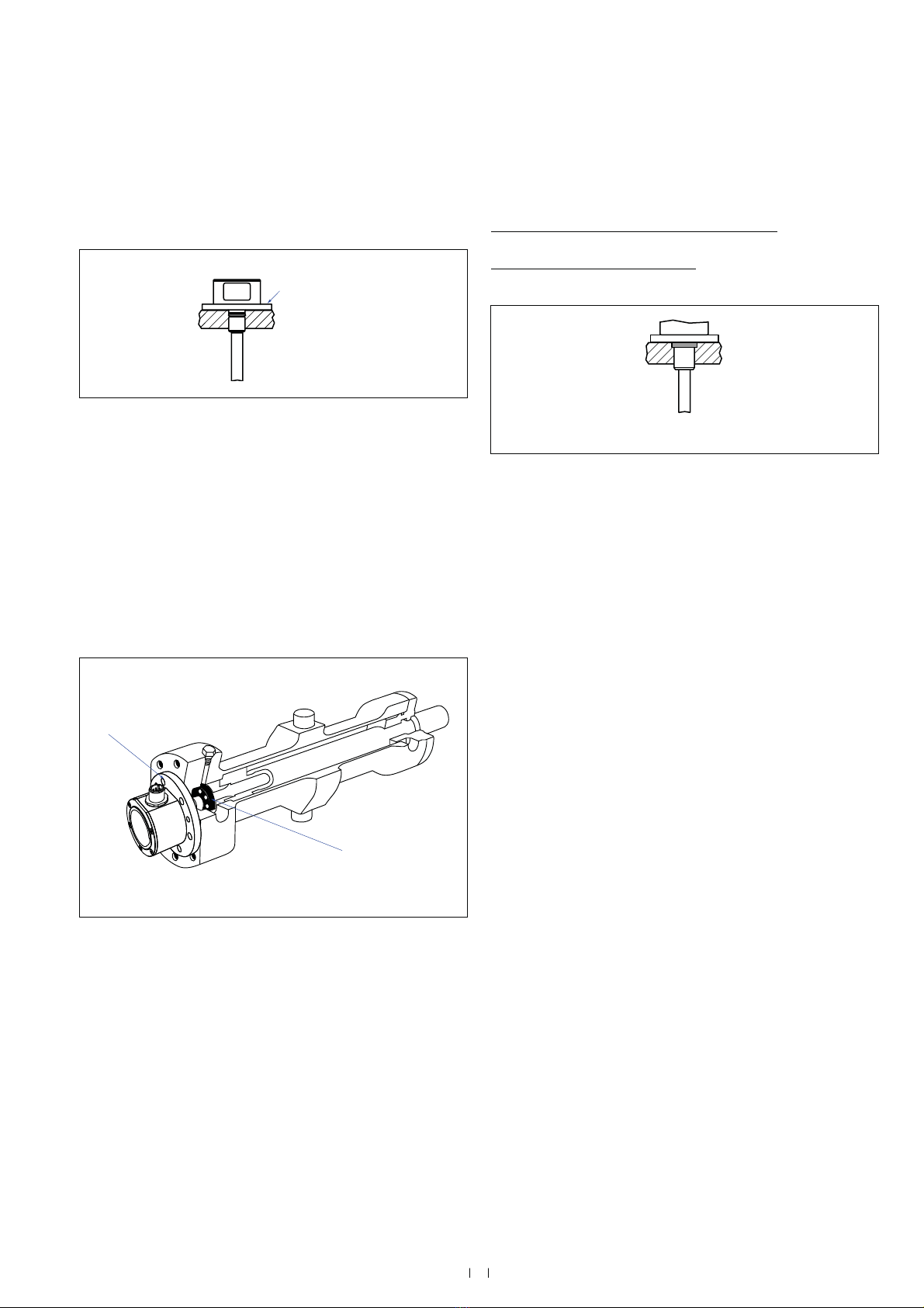
,QVWDOODWLRQRI*%ZLWKSUHVVXUHğWĠDQJH
0RXQWWKHVHQVRUYLDSUHVVXUHğWĠDQJHWKURXJKWKHERUHVLQWKH
VHQVRUHOHFWURQLFVKRXVLQJZLWKPDFKLQHVFUHZV0ū$
,62
Fig. 4: ,QVWDOODWLRQRI*%ZLWKSUHVVXUHğWĠDQJHŊ6ʼnŊ1ʼn
Fig. 5: 6HQVRULQF\OLQGHU
Installation of a rod-style sensor in a hydraulic cylinder
The rod-style version has been developed for direct stroke measure-
ment in a hydraulic cylinder. Mount the sensor through the bores in
WKHVHQVRUHOHFWURQLFVKRXVLQJZLWKPDFKLQHVFUHZV0ū$
,62
Mounted on the face of the piston, the position magnet travels
over the rod without touching it and indicates the exact position
WKURXJKWKHURGZDOOŋLQGHSHQGHQWRIWKHK\GUDXOLFĠXLG
The pressure resistant sensor rod is installed into a bore in the
piston rod.
ydraulics sealing
6HDOWKHĠDQJHFRQWDFWVXUIDFHYLD2ULQJLQWKHXQGHUFXWDVVKRZQLQ
Fig. 6.
)RUSUHVVXUHğWĠDQJHI*%.*%1*%6
2ULQJūPP[LQSDUWQR
)RUSUHVVXUHğWĠDQJHI*%-
25LQJūPP[LQSDUWQR
Fig. 6: Sealing
1RWHWKHIDVWHQLQJWRUTXHRIPDFKLQHVFUHZVRI1P
6HDWWKHĠDQJHFRQWDFWVXUIDFHFRPSOHWHO\RQWKHF\OLQGHUPRXQWLQJ
surface.
The cylinder manufacturer determines the pressure-resistant
JDVNHWFRSSHUJDVNHW2ULQJHWF
The position magnet should not grind on the sensor rod.
7KHSLVWRQURGGULOOLQJ*%1*%6ŰPPŰLQ
*%-*%.ŰPPŰLQGHSHQGVRQWKHSUHVVXUH
and piston speed.
Adhere to the information relating to operating pressure.
Protect the sensor rod against wear.
Fastening torque
6 Nm
Sensor electronics housing
with sensor rod
Position magnet
Sealing via O-ring
in the flange undercut
1
Temposonics®GB-Series SSI
Operation Manual
0FRQQHFWRU([DPSOH:LWKĠDWIDFHGĠDQJH
Ø10 ± 0.13
(Ø 0.39 ± 0.01)
67.5
(2.66)
Ø54
(Ø 2.13)
54.5
(2.15)
13
(0.51)
4.1
(0.16)
14
(0.55)
Null zone
40
(1.57)
Dead zone
63.5
(2.5)
M12 connector
Threaded flange »M«:
M18×1.5-6g
M4 (3×)
55
(2.17)
25
(1)
Stroke length
25…3250
(1…128)
Sensor electronics
housing
39
(1.54)
Magnet
A/F 55
0FRQQHFWRU([DPSOH:LWKUDLVHGIDFHGĠDQJH
Ø10 ± 0.13
(Ø 0.39 ± 0.01)
66
(2.6)
52.5
(2.07)
13.5
(0.53)
14
(0.55)
Null zone
40
(1.57)
Sensor electronics
housing
39
(1.54)
25
(1)
M16 connector
Threaded flange »T«:
¾"-16 UNF-3A
Ø54
(Ø 2.13)
M4 (3×)
55
(2.17)
Stroke length
25…3250
(1…128)
Dead zone
63.5
(2.5)
Magnet
2.5
(0.1)
Ø 25.4
(Ø 1)
A/F 55
&DEOHRXWOHW([DPSOH:LWKĠDWIDFHGĠDQJH
Threaded flange »M«:
M18×1.5-6g
55
(2.17)
M4 (3×)
77.4
(3.05)
Ø54
(Ø 2.13)
54.5
(2.15)
22.9
(0.9)
25
(1)
4.1
(0.16)
14
(0.55)
Null zone
40
(1.57)
Stroke length
25…3250
(1…128)
Dead zone
63.5
(2.5)
Ø10 ± 0.13
(Ø 0.39 ± 0.01)
Sensor electronics
housing
39
(1.54)
Magnet
A/F 55
&RQWUROOLQJGHVLJQGLPHQVLRQVDUHLQPLOOLPHWHUVDQGPHDVXUHPHQWVLQDUHLQLQFKHV
8QOHVVRWKHUZLVHVWDWHGDSSO\WRWKHJHQHUDOWROHUDQFHVDFFRUGLQJWR',1,62P
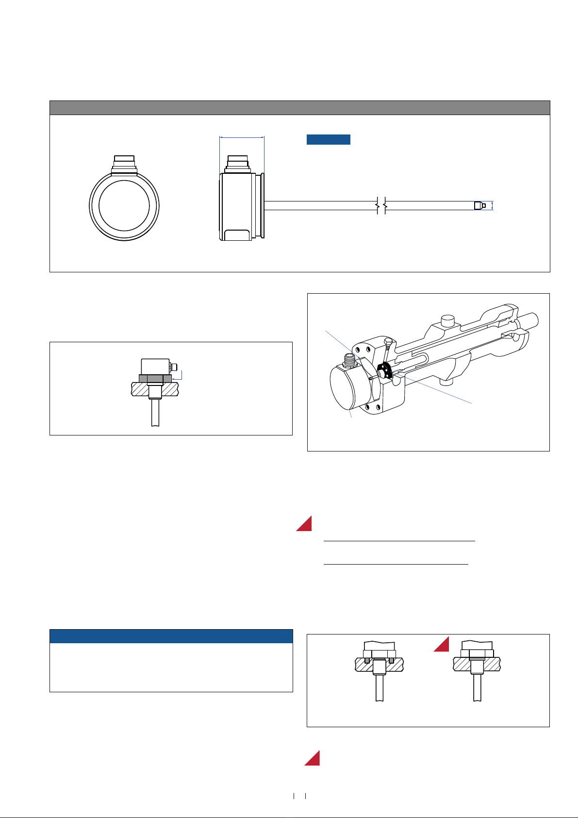
4.3 Styles and installation of Temposonics®GB- GB-T GB-B(rod sensor with threaded flange)
)LJ7HPSRVRQLFV®GB-M / GB-T
11
Temposonics® GB-Series SSI
Operation Manual
,QVWDOODWLRQRI*%ZLWKWKUHDGHGĠDQJHŊ0ʼnŊ7ʼn
)L[WKHVHQVRUURGYLDWKUHDGHGĠDQJH0ūJRUŧ81)$
Base unit xample 6 connector
34.5
(1.36)
Ø 6.81
(Ø 0.27)
&RQWUROOLQJGHVLJQGLPHQVLRQVDUHLQPLOOLPHWHUVDQGPHDVXUHPHQWVLQDUHLQLQFKHV
8QOHVVRWKHUZLVHVWDWHGDSSO\WRWKHJHQHUDOWROHUDQFHVDFFRUGLQJWR',1,62P
)LJ7HPSRVRQLFV®GB-B
Fig. 9: 0RXQWLQJH[DPSOHRIWKUHDGHGĠDQJHŊ0ʼnŊ7ʼn
NOTICE 7KH*%%LVRQO\IRUUHSODFHPHQW
8VHWKH*%%VHQVRUZLWKDURGRIWKH*%0RU*%7VHQVRURQO\
Installation of a rod-style sensor in a hydraulic cylinder
The rod-style version has been developed for direct stroke
measurement in a hydraulic cylinder. Mount the sensor via
WKUHDGHGĠDQJH
Mounted on the face of the piston, the position magnet travels
over the rod without touching it and indicates the exact position
WKURXJKWKHURGZDOOŋLQGHSHQGHQWRIWKHK\GUDXOLFĠXLG
The pressure resistant sensor rod is installed into a bore in the
piston rod.
The base unit is mounted by means of only three screws. It is the
only part that needs to be replaced if servicing is required, i.e. the
hydraulic circuit remains closed. For more information see chapter
Ń5HSODFHPHQWRIEDVHXQLWńRQSDJH
Fig. 10: 6HQVRULQF\OLQGHU
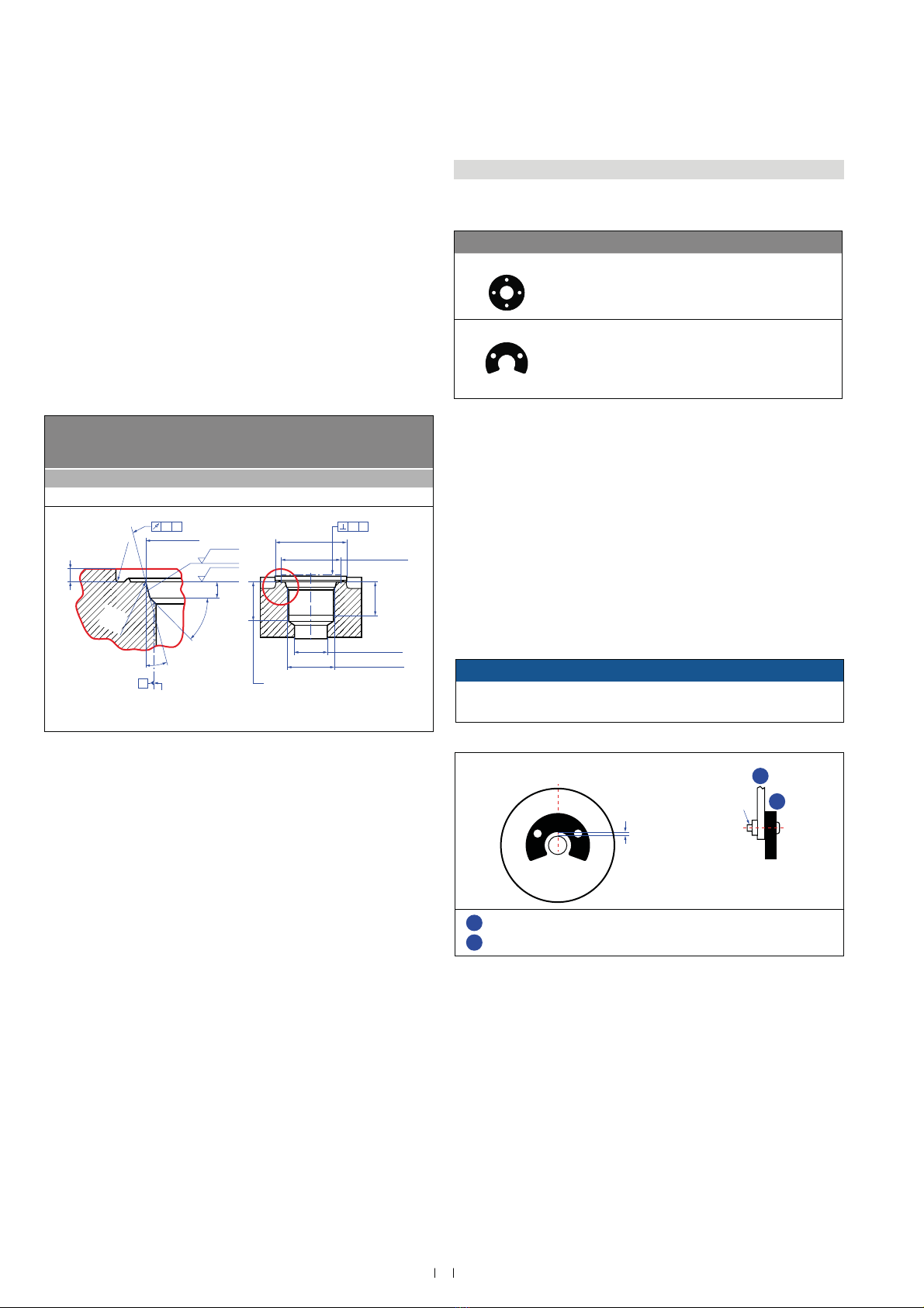
ydraulics sealing
7KHUHDUHWZRZD\VIRUVHDOLQJWKHĠDQJHFRQWDFWVXUIDFH)LJ
1. $VHDOLQJE\XVLQJDQ2ULQJHJūPPūLQ
in a cylinder end cap groove.
2. A sealing via an O-ring in the undercut.
)RUWKUHDGHGĠDQJHŧ81)$*%7
2ULQJūPPūLQSDUWQR
)RUWKUHDGHGĠDQJH0ūJ*%7
2ULQJūPPūLQSDUWQR
,QWKHFDVHRIWKUHDGHGĠDQJH0ūJDVFUHZKROHEDVHGRQ
,62)LJPXVWEHSURYLGHG6HH,62IRUIXUWKHU
information.
Fig. 11: 3RVVLELOLWLHVRIVHDOLQJ
NOTICE
The orientation of the sensor electronics housing respectively of
WKHHOHFWULFDOFRQQHFWLRQRIVHQVRUPRGHOV*%0DQG*%7FDQEH
changed after mounting. For more information see chapter “4.5
Change orientation of sensor electronics housing” on page 14.
MTS recommendation
R
R
R
Fastening torque
50 Nm
In the event of servicing, the sensor rod
with flange remains in the cylinder
Position magnet
Base unit
The sensor electronics housing
with sensing element can be replaced
Sealing via O-ring
in the flange undercut
Sealing via O-ring
in cylinder end cap groove
12
Temposonics®GB-Series SSI
Operation Manual
Fig. 12: 1RWLFHIRUWKUHDGHGĠDQJH0ūJEDVHGRQ',1,62
1RWHWKHIDVWHQLQJWRUTXHRI1P
6HDWWKHĠDQJHFRQWDFWVXUIDFHFRPSOHWHO\RQWKHF\OLQGHUPRXQWLQJ
surface.
The cylinder manufacturer determines the pressure-resistant
JDVNHWFRSSHUJDVNHW2ULQJHWF
The position magnet should not grind on the sensor rod.
7KHSLVWRQURGGULOOLQJŰPPŰLQGHSHQGVRQWKH
pressure and piston speed.
Adhere to the information relating to operating pressure.
Protect the sensor rod against wear.
1RWLFHIRUPHWULFWKUHDGHGĠDQJH
4.4 agnet instal lation
Typical use of magnets
agnet %HQHğWV
Ring magnets 5RWDWLRQDOO\V\PPHWULFDOPDJQHWLFğHOG
-magnets eight tolerances can be compensated
ounting ring magnets and -magnets
Install the magnet using non-magnetic material for mounting
device, screws, spacers etc.. The magnet must not grind on
the sensor rod. Alignment errors are compensated via the air gap.
3HUPLVVLEOHVXUIDFHSUHVVXUH0D[1PP2
)DVWHQLQJWRUTXHIRU0VFUHZV1PXVHZDVKHULIQHFHVVDU\
Minimum distance between position magnet and any magnetic
PDWHULDOKDVWREHPPLQ)LJ
If no other option exists and magnetic material is used, observe the
VSHFLğHGGLPHQVLRQV)LJ
Fig. 13: 7\SLFDOXVHRIULQJPDJQHWVDQG8PDJQHWV
NOTICE
Mount ring magnets and U-magnets concentrically.
Do not exceed the maximum acceptable gap.
Fig. 14: 0RXQWLQJRI8PDJQHWSDUWQR
&RQWUROOLQJGHVLJQGLPHQVLRQVDUHLQPLOOLPHWHUVDQGPHDVXUHPHQWVLQDUHLQLQFKHV
Thread
d
d2d3d4d5
.
.4
234
GB-
0ūJ Ű Ű 24.5 2.4 226 Ź
Ød
5
Ra 3.2
Ra 3.2
Pitch diameter
A
A
Thread
(d
1
× P)
Ød
3(Reference)
A
Ød
2
Ød
4(Gauging)
This dimension applies when
tap drill cannot pass through
entire boss.
≤ R0.4
R0.3
R0.1
Z°
4
5
°
±
5
°
L
3
L
1
L
2
L
4
A0.1 A0.2
&RQWUROOLQJGHVLJQGLPHQVLRQVDUHLQPLOOLPHWHUV
M4 1
2
Air gap
Concentric mounting
of U-magnet
Part no. 201 553:
3 ±1 (0.12 ±0.04)
Part no. 251 416-2:
1.75 ±1 (0.07 ±0.04)
U-magnet
Non-magnetic mounting plate and fasteners
1
2
13
Temposonics® GB-Series SSI
Operation Manual
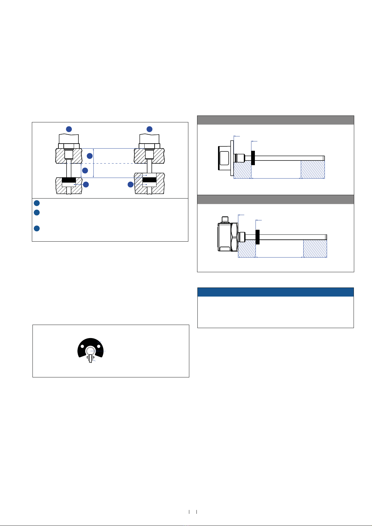
agnet mounting ith magnetic material
hen using magnetic material the dimensions of Fig. 15 must
be observed.
A.If the position magnet aligns with the drilled piston rod
B.If the position magnet is set further into the drilled piston rod,
LQVWDOODQRWKHUQRQPDJQHWLFVSDFHUHJSDUWQRDERYH
the magnet.
6HQVRUVZLWKVWURNHOHQJWKVŰPHWHUIW
6XSSRUWKRUL]RQWDOO\LQVWDOOHGVHQVRUVZLWKDVWURNHOHQJWKIURPPHWHU
mechanically at the rod end. ithout the use of a support, rod and posi -
tion magnet may be damaged. A false measurement result is also possi-
ble. onger rods require evenly distributed mechanical support over the
HQWLUHOHQJWKHJSDUWQR8VHDQ8PDJQHW)LJIRU
measurement.
Fig. 16: ([DPSOHRIVHQVRUVXSSRUW
ctie measuring range
The technical data of each sensor is checked as well as documented
DQGWKHDFWLYHVWURNHOHQJWKXVHIXOHOHFWULFDOVWURNHZLWKLWVVWDUWDQG
HQGSRVLWLRQLVDGMXVWHGGXULQJğQDOLQVSHFWLRQDQGWHVWLQJ)LJ
To ensure that the entire measuring range can be used electrically, the
SRVLWLRQPDJQHWPXVWEHPRXQWHGPHFKDQLFDOO\DVIROORZV
*%6HULHVZLWKSUHVVXUHğWĠDQJHZLWKULQJ8PDJQHW
40 Stroke length 63.5
Reference edge of mounting
Start position
*%6HULHVZLWKWKUHDGHGĠDQJHZLWKULQJ8PDJQHW
40 Stroke length 63.5
Reference edge of mounting
Start position
)LJ$FWLYHPHDVXULQJUDQJH
NOTICE
On all sensors, the areas left and right of the active stroke length
DUHSURYLGHGIRUQXOODQGGHDG]RQH7KHVH]RQHVVKRXOGQRWEH
used for measurement, however the active stroke length
can be exceeded.
&RQWUROOLQJGHVLJQGLPHQVLRQVDUHLQPLOOLPHWHUVDQGPHDVXUHPHQWVLQDUHLQLQFKHV
Fig. 15: ,QVWDOODWLRQZLWKPDJQHWLFPDWHULDO
Magnet Magnet
1
2
3 3
A B
Magnetic
material
1XOO]RQHGHSHQGVRQVHQVRUPRGHOVHH)LJ
2Distance between position magnet and any magnetic material
ŰPPŰLQ
31RQPDJQHWLFVSDFHUŰPPŰLQŋ
5HFRPPHQGDWLRQPPLQ
U-magnet
Sensor rod
Non-magnetic fixing clip

14
Temposonics®GB-Series SSI
Operation Manual
4.6 Replacement of ase unit
7KHEDVHXQLWRIWKHVHQVRUPRGHOV*%0DQG*%7LVUHSODFHDEOHDV
shown in Fig. 19. The sensor can be replaced without interrupting the
hydraulic circuit.
Base unit GB-B
Sensor electronics housing
Plastic tube with
inner sensor element
. oosen the scres.
You do not need to loosen the screws
(3 screws DIN 915 M4x6 A2)
completely. Normally it is
sufficient if you turn the
screws 4 ×.
A/F 2
2. ull out the ase unit.
There is an O-ring inside the
flange of the GB-M and GB-T
sensor.
Position the O-ring as shown in
the figure before inserting the
new base unit (GB-B).
O-ring
3. Insert the ne ase unit. T ighten the scres.
Fastening torque: 1.6 Nm
4.5 hange orientation of sensor electronics housing
The orientation of the sensor electronics housing respectively of
WKHHOHFWULFDOFRQQHFWLRQRIVHQVRUPRGHOV*%0DQG*%7FDQEH
FKDQJHGDIWHUPRXQWLQJ)ROORZWKHLQVWUXFWLRQVLQ)LJ
)LJ$OLJQVHQVRUHOHFWURQLFVKRXVLQJUHVSHFWLYHO\HOHFWULFDOFRQQHFWLRQRI*%0*%7
Fig. 19: 5HSODFHPHQWRIWKHEDVHXQLW*%%
GB- GB-T sensor
. oosen the scres.
You do not need to loosen the screws (3 screws DIN 915 M4x6 A2)
completely. Normally it is sufficient if you turn the screws 3 ×.
A/F 2
2. Turn the sensor electronics housing to the desired orientation.
360°
3. Tighten the scres.
Fastening torque: 1.6 Nm
15
Temposonics® GB-Series SSI
Operation Manual
4. lectrical connection
3ODFHPHQWRILQVWDOODWLRQDQGFDEOLQJKDYHGHFLVLYHLQĠXHQFHRQWKH
VHQVRUŁVHOHFWURPDJQHWLFFRPSDWLELOLW\(0&+HQFHFRUUHFW
LQVWDOODWLRQRIWKLVDFWLYHHOHFWURQLFV\VWHPDQGWKH(0&RIWKHHQWLUH
system must be ensured by using suitable metal connectors, shielded
cables and grounding. Overvoltages or faulty connections can damage
the sensor electronics despite protection against wrong polarity.
Instruction for connection
Use low-resistance twisted pair and shielded cables. Connect the
shield to ground externally via the controller equipment.
eep control and signal leads separate from power cables and
VXIğFLHQWO\IDUDZD\IURPPRWRUFDEOHVIUHTXHQF\LQYHUWHUVYDOYH
lines, relays, etc..
Use only metal connectors and connect the shielding to the
connector housing.
eep the connection surface at both shielding ends as large as
possible. Connect the cable clamps to function as a ground.
eep all non-shielded leads as short as possible.
eep the ground connections short and with a large cross section.
Avoid ground loops.
ith potential differences between machine and electronics earth
FRQQHFWLRQVQRFRPSHQVDWLQJFXUUHQWVDUHDOORZHGWRĠRZDFURVV
the cable shielding.
5HFRPPHQGDWLRQ,QVWDOOSRWHQWLDOFRPSHQVDWLQJOHDGVZLWKODUJH
cross section, or use cables with separate double shielding, and
connect only one end of the shield.
8VHRQO\VWDELOL]HGSRZHUVXSSOLHVDQGPDNHVXUHWKDWWKHVSHFLğHG
connecting values are met.
Fig. 20: &RQQHFWRUZLULQJ'0
Fig. 21: &RQQHFWRUZLULQJ'0
onnector iring
Connect the sensor directly to the control system, indicator or other
HYDOXDWLQJV\VWHPVDVIROORZV
Fig. 22: &RQQHFWRUZLULQJFDEOHRXWOHW
NOTICE
Do not mount the sensors in the area of strong magnetic or
HOHFWULFQRLVHğHOGV
1HYHUFRQQHFWGLVFRQQHFWWKHVHQVRUZKHQYROWDJHLVDSSOLHG
Grounding of rod sensors
Connect the sensor electronics housing to the machine ground via
SUHVVXUHğWĠDQJHUHVSHFWLYHO\YLDWKUHDGHGĠDQJH
4
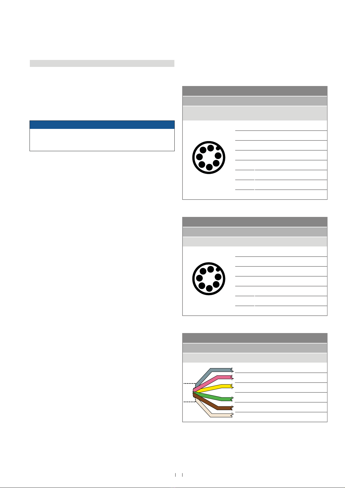
Signal poer supply
2 male connector
-coded
in unction
1
4
2
6
3
5
7
iew on sensor
1&ORFN
2&ORFNũ
3'DWD
4'DWDũ
51RWFRQQHFWHG
61RWFRQQHFWHG
79'&ũ
'&*URXQG9
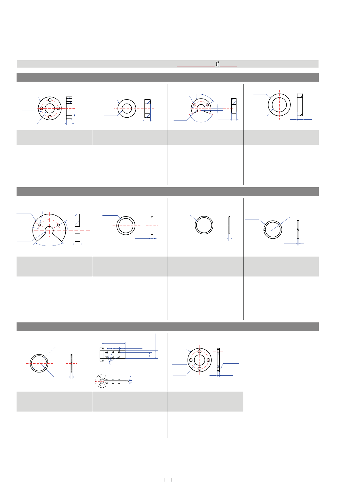
Signal poer supply
6 male connector in untion
1
4
2
6
3
5
7
iew on sensor
1'DWDũ
2'DWD
3&ORFN
4&ORFNũ
59'&ũ
6'&*URXQG9
71RWFRQQHFWHG
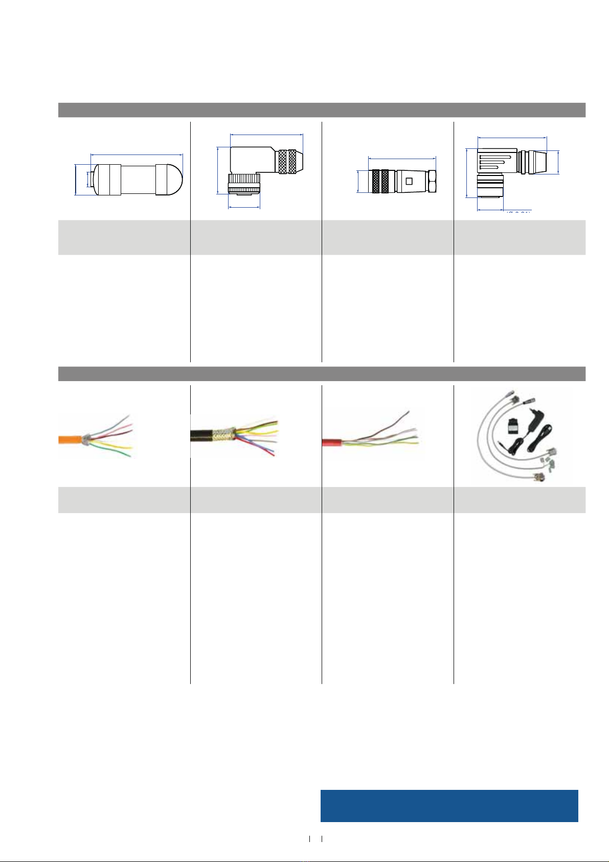
GB ith cale out let T
Signal poer supply
ale olor unction
*< 'DWDũ
P 'DWD
<( &ORFN
*1 &ORFNũ
%1 9'&ũ
'&*URXQG9
16
Temposonics®GB-Series SSI
Operation Manual
4. reuently ordered accessories
&RQWUROOLQJGHVLJQGLPHQVLRQVDUHLQPLOOLPHWHUVDQGPHDVXUHPHQWVLQDUHLQLQFKHV
Additional options available in our $FFHVVRULHV*XLGH 551 444
osition magnets
Ø 32.8
(Ø 1.29)
Ø 23.8
(Ø 0.94)
Ø 13.5
(Ø 0.53)
Ø 4.3
(Ø 0.17)
7.9
(0.31)
Ø 25.4
(
Ø
1)
Ø 13.5
(
Ø
0.53) 7.9
(0.31)
32.
1.29
23.
.94
13.5
.53
4.3
.17
6
14
3
.12
7.9
.31
Ø 19.8
(Ø 0.78)
Ø 30.5
(Ø 1.2)
7.6
(0.3)
Ring magnet 33
art no. 2 542-2
Ring magnet 25.4
art no. 4 533
-magnet 33
art no. 25 46-2
Ring magnet
art no. 42 36
0DWHULDO3$IHUULWH*)
:HLJKW$SSUR[J
6XUIDFHSUHVVXUH0D[1PP2
)DVWHQLQJWRUTXHIRU0VFUHZV1P
2SHUDWLQJWHPSHUDWXUH
ũĽŹ&ũĽŹ)
0DWHULDO3$IHUULWH
:HLJKW$SSUR[J
6XUIDFHSUHVVXUH0D[1PP2
2SHUDWLQJWHPSHUDWXUH
ũĽŹ&ũĽŹ)
0DWHULDO3$IHUULWH*)
:HLJKW$SSUR[J
6XUIDFHSUHVVXUH0D[1PP2
)DVWHQLQJWRUTXHIRU0VFUHZV1P
2SHUDWLQJWHPSHUDWXUH
ũĽŹ&ũĽŹ)
0DWHULDO3$IHUULWHFRDWHG
:HLJKW$SSUR[J
6XUIDFHSUHVVXUH0D[1PP2
2SHUDWLQJWHPSHUDWXUH
ũĽŹ&ũĽŹ)
osition magnet -rings Bac-up ring
Ø 4.5 (Ø 0.18)
Ø 63.5
(Ø 2.5)
Ø 42
(Ø 1.65)
Ø 16
(Ø 0.63) 97°
30°
9.5
(0.37)
15
.59
2
.
Ø 17
(Ø 0.67)
Ø 2
(Ø 0.07)
Ø 18
(Ø 0.71)
1.4
(0.05)
1.5
(0.06)
-magnet 63.5
art no. 2 553
2ULQJIRUSUHVVXUHğWĠDQJHPP
art no. 56 53
2ULQJIRUSUHVVXUHğWĠDQJHPP
art no. 56 43
%DFNXSULQJIRUSUHVVXUHğWĠDQJH
PP
art no. 56 5
0DWHULDO3$*)
PDJQHWVFRPSRXQGğOOHG
:HLJKWApprox. 26 g
6XUIDFHSUHVVXUH1PP2
)DVWHQLQJWRUTXHIRU0VFUHZV1P
2SHUDWLQJWHPSHUDWXUH
ũĽŹ&ũĽŹ)
0DWHULDO)OXRURHODVWRPHU
'XURPHWHU6KRUH$
0DWHULDO).0
'XURPHWHU6KRUH$
2SHUDWLQJWHPSHUDWXUH
ũĽŹ&ũĽŹ)
0DWHULDO37)(EURQ]H
Bac-up ring ptional installation hardare agnet spacer
1.4
(0.05)
1.5
(0.06)
Ø 21
(Ø 0.82)
1.4
1.5
Ø 21
20 (0.79)
60 (2.36)
16 (0.63)
12 (0.47)
3.2 (0.13)
Ø 3.2 (Ø 0.13)
M3 fastening screws (6×) Ø 14.3
(Ø 0.56)
Ø 23.8
(Ø 0.94)
Ø 31.8
(Ø 1.25)
Ø 4.3
(Ø 0.17)
3.2
(0.13)
%DFNXSULQJIRUSUHVVXUHğWĠDQJH
PP
art no. 56 43
)L[LQJFOLSIRUURGZLWKPP
art no. 56 4
agnet spacer
art no. 4 633
0DWHULDO37)( $SSOLFDWLRQ8VHGWRVHFXUHVHQVRU
URGVPPLQZKHQ
using an U-magnet or block magnet
0DWHULDO%UDVVQRQPDJQHWLF
0DWHULDO$OXPLQXP
:HLJKW$SSUR[J
6XUIDFHSUHVVXUH0D[1PP2
)DVWHQLQJWRUTXHIRU0VFUHZV1P
17
Temposonics® GB-Series SSI
Operation Manual
5/ Follow the manufacturers mounting instructions
&RQWUROOLQJGHVLJQGLPHQVLRQVDUHLQPLOOLPHWHUVDQGPHDVXUHPHQWVLQDUHLQLQFKHV 0DQXDOV6RIWZDUH'0RGHOVDYDLODEOHDW
.mtssensors.com
ale connectors 5
~ 60
(~ 2.36)
M12×1
Ø
20 (Ø 0.79)
20
(0.79)
~ 57
(~ 2.24)
38
(1.5)
54
(2.13)
Ø 18
(Ø 0.71)
~ 54
(~2.13)
~ 38
(~ 1.5)
Ø 20.5
(Ø 0 81)
Ø 18
(Ø 0.71)
2 -coded female connector
pin, straight
art no. 3 64
2 -coded female connector
pin, angled
art no. 3 6
6 female connector pin, straight
art no. 3 624
6 female connector pin, angled
art no. 56
+RXVLQJ*'=Q$/
7HUPLQDWLRQ6FUHZ
&RQWDFWLQVHUW&X=Q
&DEOHĽPPĽLQ
:LUHPP2
2SHUDWLQJWHPSHUDWXUH
ũĽŹ&ũĽŹ)
,QJUHVVSURWHFWLRQ,3FRUUHFWO\ğWWHG
)DVWHQLQJWRUTXH1P
+RXVLQJ*'=Q$/
7HUPLQDWLRQ6FUHZ
&RQWDFWLQVHUW&X=Q
&DEOHĽPPĽLQ
:LUHPP2
2SHUDWLQJWHPSHUDWXUH
ũĽŹ&ũĽŹ)
,QJUHVVSURWHFWLRQ,3FRUUHFWO\ğWWHG
)DVWHQLQJWRUTXH1P
0DWHULDO=LQFQLFNHOSODWHG
7HUPLQDWLRQ6ROGHU
&RQWDFWLQVHUW6LOYHUSODWHG
&DEOHFODPS3*
&DEOHĽPPĽLQ
2SHUDWLQJWHPSHUDWXUH
ũĽŹ&ũĽŹ)
,QJUHVVSURWHFWLRQ,3,3
FRUUHFWO\ğWWHG
)DVWHQLQJWRUTXH1P
0DWHULDO=LQFQLFNHOSODWHG
7HUPLQDWLRQ6ROGHU
&RQWDFWLQVHUW6LOYHUSODWHG
&DEOHĽPPĽLQ
:LUHPPš$:*
2SHUDWLQJWHPSHUDWXUH
ũĽŹ&ũĽŹ)
,QJUHVVSURWHFWLRQ,3FRUUHFWO\ğWWHG
)DVWHQLQJWRUTXH1P
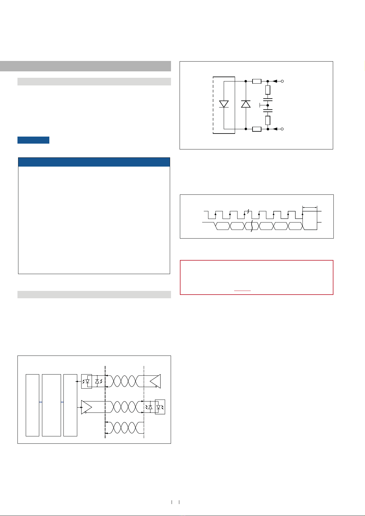
ales rogramming tool
R cale
art no. 53 52
7HĠRQ®cale
art no. 53 2
Silicone cale
art no. 53 3
rogramming it
art no. 254 5
0DWHULDO385MDFNHWRUDQJH
)HDWXUHV7ZLVWHGSDLUVKLHOGHG
KLJKO\ĠH[LEOH
&DEOHPPLQ
&URVVVHFWLRQūūPP2
%HQGLQJUDGLXVūIL[HGLQVXODWLRQ
2SHUDWLQJWHPSHUDWXUH
0DWHULDO7HĠRQ®MDFNHWEODFN
)HDWXUHV7ZLVWHGSDLUVKLHOGHGĠH[LEOH
&DEOHPPLQ
&URVVVHFWLRQūūPPš
%HQGLQJUDGLXVŋū
ğ[HGLQVWDOODWLRQ
2SHUDWLQJWHPSHUDWXUH
ũĽŹ&ũĽŹ)
0DWHULDO6LOLFRQHMDFNHWUHG
)HDWXUHV7ZLVWHGSDLUVKLHOGHG
KLJKO\ĠH[LEOH
&DEOHPPLQ
&URVVVHFWLRQūūPPš
%HQGLQJUDGLXVūğ[HGLQVWDOODWLRQ
2SHUDWLQJWHPSHUDWXUH
ũĽŹ&ũĽŹ)
.LWLQFOXGHV
ūLQWHUIDFHFRQYHUWHUER[
ūSRZHUVXSSO\
ūFDEOHFPZLWK0IHPDOH
FRQQHFWRUSLQVWUDLJKWŋ'VXE
IHPDOHFRQQHFWRUSLQVWUDLJKW
ūFDEOHFPZLWK0IHPDOH
FRQQHFWRUSLQVWUDLJKWŋ'VXE
IHPDOHFRQQHFWRUSLQVWUDLJKW
ūFDEOHFPZLWKūWHUPLQDO
clamp D-sub female connector
SLQVWUDLJKW
ū86%FDEOH
6RIWZDUHLVDYDLODEOHDW
www.mtssensors.com
Temposonics®GB-Series SSI
Operation Manual
5. peration
5. Getting started
7KHVHQVRULVIDFWRU\VHWWRLWVRUGHUVL]HVDQGDGMXVWHGLHWKHGLV-
WDQFHEHWZHHQPDJQHWDQGĠDQJHLVVSHFLğHGLQUHVROXWLRQVWHSV
([DPSOH66,YDOXHDWWKHVWDUWRIPHDVXULQJUDQJHPPZLWK
a resolution of 1 m
NOTICE If necessary, the SSI sensors can be re-adjusted using
the service tool described below.
5.2 3URJUDPPLQJDQGFRQğJXUDWLRQ
SSI interface
The interface of Temposonics®position sensors corresponds to SSI
industry standard for absolute encoders. Its displacement value is
HQFRGHGLQDELWELQDU\RUJUD\IRUPDWDQGWUDQVPLWWHG56
FRPSDWLEOHYLDZLUHVŋLQGHSHQGHQWRIGDWDZLGWKRIWKHFRGHUHVR-
OXWLRQ
The absolute, parallel position data is continually updated by the
sensor and converted by the shift-register into a serial bit stream
)LJ
Fig. 23: 6FKHPDWLFFRQQHFWLRQ
Fig. 24: ,QSXWZLULQJFORFNFORFNũ
Fig. 25: 7LPLQJGLDJUDP
TS Sensors programming tools
Temposonics®SRVLWLRQVHQVRUVFDQEHDGDSWHGWRPRGLğHG
measurement tasks very easily via the connecting leads without
opening the sensor. For this, the MTS Sensors programming kit is
DYDLODEOHVHHSDJH
7KLVFKDSWHUGHVFULEHVŃSURJUDPPLQJDQGFRQğJXUDWLRQńRIWKH
*%66,VHQVRUYLDFDEOHFRQQHFWLRQ
Ń3URJUDPPLQJDQGFRQğJXUDWLRQńYLD%OXHWRRWK®connection are
explained in document 551649.
NOTICE
sere during commissioning
1. efore initial switch-on, check carefully if the sensor has been
connected correctly.
2. Position the magnet in the measuring range of the sensor
GXULQJğUVWFRPPLVVLRQLQJDQGDIWHUUHSODFHPHQWRIWKHPDJQHW
(QVXUHWKDWWKHVHQVRUFRQWUROV\VWHPFDQQRWUHDFWLQDQ
uncontrolled way when switching on.
(QVXUHWKDWWKHVHQVRULVUHDG\DQGLQRSHUDWLRQPRGHDIWHU
switching on.
5. Check the pre-set span start and end values of the measuring
UDQJH)LJDQGFRUUHFWWKHPYLDWKHFXVWRPHUłVFRQWURO
system if necessary, or via the MTS Sensors service tool.
The operation of the service tool is described in detail on the
following pages.
Sensor input
91 Ω 7 mA
Clock (+)
100 Ω
LED
100 Ω
Clock (−)
91 Ω
Optocoupler
2 V
1 nF
1 nF
Clock (+)
Data (+) MSB LSB
Clock interval min. 16 μs
Logic diagram Sensor Controller
Clock (+)
Clock (−)
Optocoupler
Driver
Data (+)
Data (−)
+24 VDC
0 V
ASIC for parallel and
absolute position data
Microprocessor system
position value = 24 / 25 bit
binary or gray
Shift register
parallel serial converter
19
Temposonics® GB-Series SSI
Operation Manual
NOTICE
1HYHUFRQQHFWGLVFRQQHFWWKHVHQVRUZKHQYROWDJHLVDSSOLHG
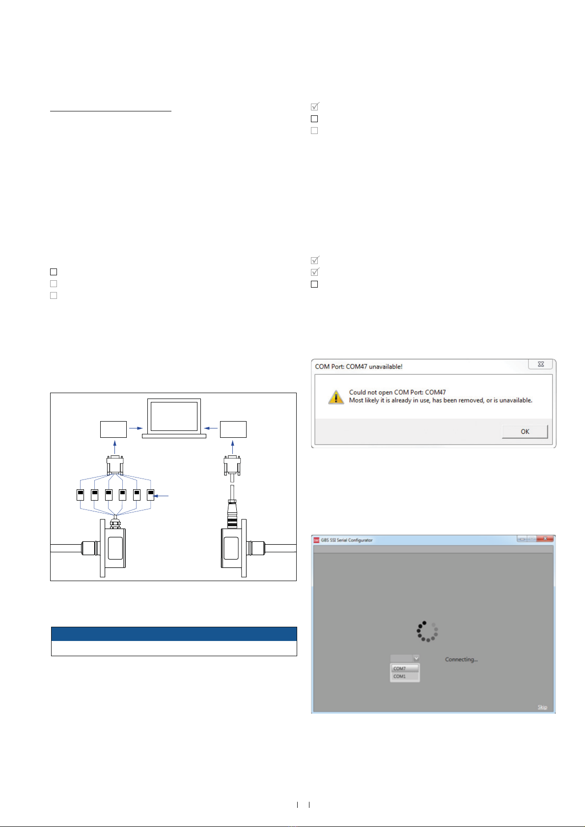
Fig. 26: &RQQHFW3&SURJUDPPHUH[DPSOHRI*%6*%1
IRUVHQVRUVZLWKFDEOHRXWOHWRQWKHOHIWIRUVHQVRUVZLWKFRQQHFWRURXWOHWRQWKHULJKW
Download the current software version from www.mtssensors.com.
,QVWDOOWKHVRIWZDUH1(7)UDPHZRUNDVDGPLQLVWUDWRU&RS\WKHSURJUDP
*%6B66,B6HULDOB&RQğJXUDWRUH[HWR\RXUFRPSXWHUDQGVWDUWLW
6\VWHPUHTXLUHPHQWV
Microsoft indows 7 operating system
0LFURVRIW1(7)UDPHZRUNIURPYHUVLRQRUKLJKHU
$IWHUVWDUWLQJWKHSURJUDP*%666,6HULDO&RQğJXUDWRUWKHVRIWZDUH
connects to the last selected COM Port and the user interface opens
)LJ,IWKH&203RUWLVQRWDYDLODEOHDQHUURUPHVVDJHDSSHDUV
)LJ
6HOHFWWKHULJKW&203RUWIURPWKHOLVWH[DPSOHVHH)LJ
The application will automatically restart and the user interface opens
)LJ
6WHS&RQQHFW3&SURJUDPPHU
Step 2 Install softare
6WHS6WDUWSURJUDP
6WHS&RQQHFW3&SURJUDPPHU
6WHS,QVWDOOVRIWZDUH
Step 3 Start program
Programming kit, part no. 254 59
The PC programmer is a hardware converter between sensor and
serial PC interface. It can be used for adjusting sensor parameters via
computer and the MTS Sensors programming software. The software
for reading and adjusting the sensors requires a indows computer
ZLWKDIUHH86%SRUW<RXFDQDGMXVWWKHIROORZLQJSDUDPHWHUV
Data length and data format
5HVROXWLRQDQGPHDVXULQJGLUHFWLRQ
6\QFKURQRXVDV\QFKURQRXVPHDVXUHPHQW
0HDVXUHPHQWğOWHUPRYLQJDYHUDJHRIRUPHDVXUHPHQWV
Connect the PC programmer with the sensor via the corresponding
adapter cable.
Connect the PC programmer to a US port of the computer.
Connect the power supply via connector.
7KHRXWHUFRQWDFWRIWKHFRQQHFWRULV9JURXQGWKHLQQHUFRQWDFW
is 24 DC.
Step onnect programmer
6WHS,QVWDOOVRIWZDUH
6WHS6WDUWSURJUDPP
)LJ(UURUPHVVDJH&203RUWLVQRWDYDLODEOH
)LJ6HOHFW&203RUW
GY WHBN
WHBN
GY
PK
PK
YE
YE
GN
GN
USB
converter
USB
converter
Spring terminal
2
Temposonics®GB-Series SSI
Operation Manual
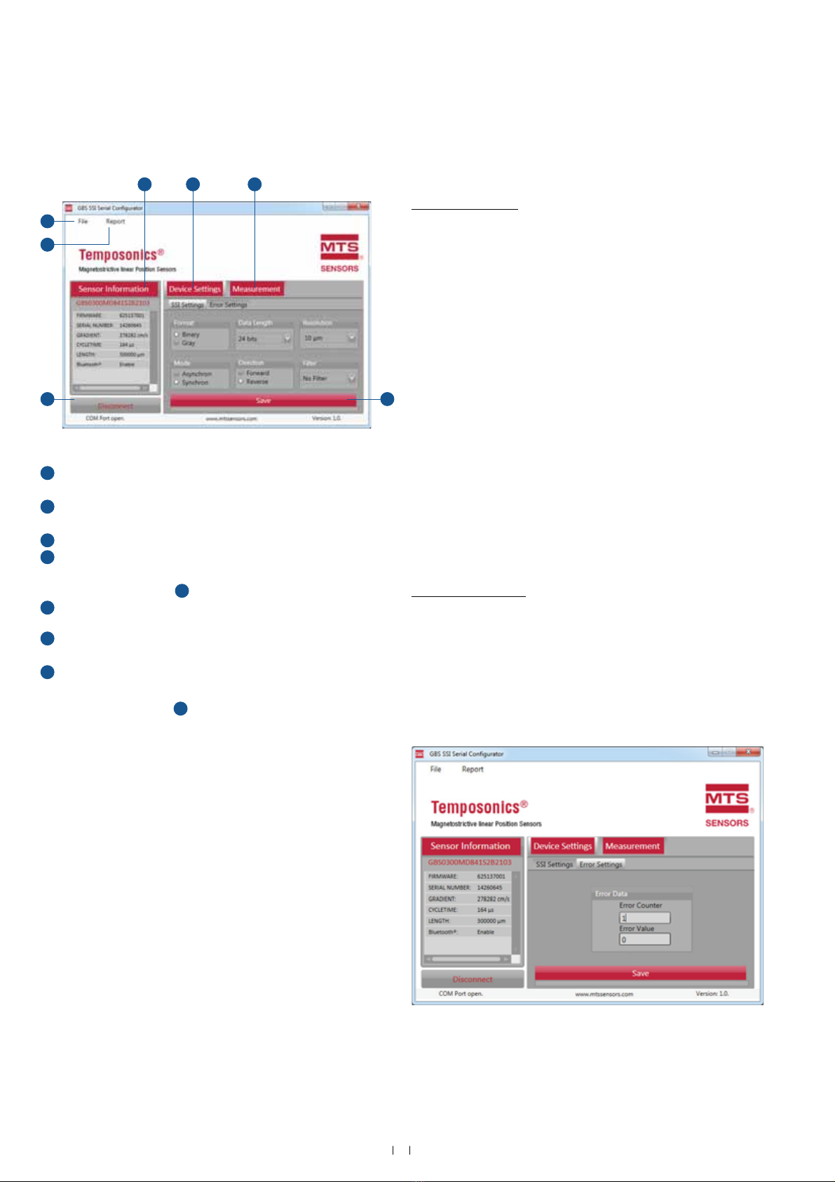
Fig. 29: 8VHULQWHUIDFH*%6HULDO&RQğJXUDWRU
GB SSI softare user interface
Sensor Information contains the invariable sensor parameters,
which were read in automatically when the sensor is connected.
2In the eice SettingsPHQXWKHFRQğJXUDEOHSDUDPHWHUV
66,6HWWLQJV(UURU6HWWLQJVRIWKHVHQVRUFDQEHVHW
3The easurement menu shows the current position of the magnet.
4The Sae button saves any parameter changes you have made.
After that the software restarts for the changes to take effect. The
function easurement 3will then be available again.
5The button isconnect breaks the connection to the COM Port
and closes the software.
6y clicking Report a report document is generated to provide
sensor information.
The ilePHQXDOORZVWKHIROORZLQJVHWWLQJVVHHDOVR)LJ
1. pen8SORDGVGHYLFHVHWWLQJVIURPD;0/ğOHWRWKHVHQVRU
Click the Sae button 4to complete the upload
2. Sae as6DYHVWKHFXUUHQWGHYLFHVHWWLQJVDV;0/ğOH
3. Restore actory Settings5HVWRUHVDQGVDYHVWKHVHQVRUłVIDFWRU\
settings
4. lose&ORVHVWKHVRIWZDUHDSSOLFDWLRQZLWKRXWVDYLQJDQ\
parameters
eice Settings
7KHIROORZLQJSDUDPHWHUVFDQEHPRGLğHG
66,6HWWLQJV)LJ
)RUPDW BinaryGray
'DWD/HQJWK 24 its25 its
5HVROXWLRQ 5 m m2 m 5 m m
0RGH synchron
In asynchronous mode the sensor starts
measuring and provides the position independent
of the PC.
Synchron
In synchronous mode the output of the Temposonics®
SSI sensor is matched to the data request cycle of the
controller.
'LUHFWLRQ orard
Ascending position values from sensor electronics
housing to rod end
Reerse
Ascending position values from rod end to sensor
electronics housing
)LOWHU o ilterilter g. 2ilter g. 4ilter g.
0RYLQJDYHUDJHRIRUPHDVXUHPHQWVIRUQRLVH
reduction
(UURU6HWWLQJV)LJ
(UURU&RXQWHU
(UURU9DOXH
The rror ounter and rror alue settings determine, how often an
HUURUKDVWRRFFXUrror ounterVRWKDWDFHUWDLQrror alue is
shown. The standard settings for the rror ounter is “1” and for the
rror alue it is “”. So every error is shown with an error value of “”.
oth parameters are changeable.
Fig. 30: Error Settings
2 3
45
6
This manual suits for next models
7
Table of contents
Other Temposonics Accessories manuals


