Temposonics E Series User manual

Operation Manual
E-Series IO-Link
Magnetostrictive Linear Position Sensors

Temposonics® E-Series IO-Link
Operation Manual
Table of contents
1. Introduction..................................................................................................................................................... 3
1.1 Purpose and use of this manual ................................................................................................................................................................ 3
1.2 Used symbols and warnings ..................................................................................................................................................................... 3
2. Safety instructions............................................................................................................................................. 3
2.1 Intended use.............................................................................................................................................................................................. 3
2.2 Forseeable misuse..................................................................................................................................................................................... 3
2.3 Installation, commissioning and operation................................................................................................................................................ 4
2.4 Safety instructions for use in explosion-hazardous areas.......................................................................................................................... 4
2.5 Warranty.................................................................................................................................................................................................... 4
2.6 Return ....................................................................................................................................................................................................... 4
3. Identification.................................................................................................................................................... 5
3.1 Order code of Temposonics®EH ............................................................................................................................................................... 5
3.2 Order code of Temposonics® EP/EL........................................................................................................................................................... 6
3.3 Order code of Temposonics® EP2.............................................................................................................................................................. 7
3.4 Order code of Temposonics® ER................................................................................................................................................................ 8
3.5 Nameplate ................................................................................................................................................................................................. 9
3.6 Approvals .................................................................................................................................................................................................. 9
3.7 Scope of delivery....................................................................................................................................................................................... 9
4. Product description and commissioning ..................................................................................................................10
4.1 Functionality and system design ............................................................................................................................................................. 10
4.2 Styles and installation of Temposonics® EH............................................................................................................................................. 11
4.3 Styles and installation of Temposonics® EP/EL........................................................................................................................................ 13
4.4 Styles and installation of Temposonics® EP2........................................................................................................................................... 14
4.5 Styles and installation of Temposonics® ER............................................................................................................................................. 15
4.6 Magnet installation .................................................................................................................................................................................. 16
4.7 Electrical connections.............................................................................................................................................................................. 18
4.8 Frequently ordered accessories............................................................................................................................................................... 19
5. Operation.......................................................................................................................................................21
5.1 Identification parameter........................................................................................................................................................................... 22
5.2 Standard commands ............................................................................................................................................................................... 22
5.3 Measuring parameter .............................................................................................................................................................................. 23
5.4 Offset....................................................................................................................................................................................................... 23
5.5 Switch points........................................................................................................................................................................................... 25
5.6 Set measurement range .......................................................................................................................................................................... 26
5.7 Error/warning messages ......................................................................................................................................................................... 27
5.8 Data storage mechanism......................................................................................................................................................................... 28
5.9 Device access lock .................................................................................................................................................................................. 29
6. Maintenance and troubleshooting .........................................................................................................................29
7.1 Error conditions, troubleshooting............................................................................................................................................................ 29
7.2 Maintenance............................................................................................................................................................................................ 29
7.3 Repair...................................................................................................................................................................................................... 29
7.4 List of spare parts ................................................................................................................................................................................... 29
7.5 Transport and storage ............................................................................................................................................................................. 29
7. Removal from service/dismantling ........................................................................................................................29
8. Technical data.................................................................................................................................................30
8.1 Technical data of Temposonics® EH......................................................................................................................................................... 30
8.2 Technical data of Temposonics® EP/EL.................................................................................................................................................... 31
8.3 Technical data of Temposonics® EP2 ....................................................................................................................................................... 32
8.4 Technical data of Temposonics® ER......................................................................................................................................................... 33
9. Appendix .......................................................................................................................................................34

Temposonics® E-Series IO-Link
Operation Manual
I 3 I
1.2 Used symbols and warnings
Warnings are intended for your personal safety and for avoidance of
damage to the described product or connected devices. In this doc-
umentation, safety information and warnings to avoid dangers that
might affect the life and health of operating or service personnel or
cause material damage are highlighted by the pictogram defined
below.
1. Introduction
1.1 Purpose and use of this manual
Before starting the operation of Temposonics position sensors, read
this documentation thoroughly and follow the safety information.
Keep the manual for future reference!
Symbol Meaning
NOTICE
This symbol is used to point to situations
that may lead to material damage, but not
to personal injury.
2. Safety instructions
2.1 Intended use
This product may be used only for the applications defined under item
1 and only in conjunction with the third-party devices and components
recommended or approved by Temposonics. As a prerequisite of
proper and safe operation the product requires correct transport,
storage, mounting and commissioning and must be operated with
utmost care.
1. The sensor systems of all Temposonics®series are intended
exclusively for measurement tasks encountered in industrial,
commercial and laboratory applications. The sensors are
considered as system accessories and must be connected
to suitable evaluation electronics, e.g. a PLC, IPC, indicator
or other electronic control unit.
Foreseeable misuse Consequence
Wrong sensor connection The sensor will not work
properly or can be damaged
Operate the sensor out of the
operating temperature range
No signal output –
the sensor can be damaged
Power supply is out of the
defined range
Signal output is wrong/
no signal output/
the sensor will be damaged
Position measurement is
influenced by an external
magnetic field
Signal output is wrong
Cables are damaged
Short circuit – the sensor can
be damaged/sensor does not
respond
Spacers are missing/
installed in a wrong order Error in position measurement
Wrong connection
of ground/shield
Signal output is disturbed –
the electronics can be damaged
Use of a magnet that is not
specified by Temposonics Error in position measurement
Do not reprocess the sensor afterwards.
The sensor might be damaged.
Do not step on the sensor.
The sensor might be damaged.
2.2 Forseeable misuse
The content of this technical documentation and of its appendix
is intended to provide information on mounting, installation and
commissioning by qualified automation personnel 1or instructed
service technicians who are familiar with the project planning and
dealing with Temposonics sensors.
1/ The term “qualified technical personnel” characterizes persons who:
•are familiar with the safety concepts of automation technology applicable to the
particular project
•are competent in the field of electromagnetic compatibility (EMC)
•have received adequate training for commissioning and service operations
•are familiar with the operation of the device and know the information required
for correct operation provided in the product documentation

Temposonics® E-Series IO-Link
Operation Manual
I 4 I
2.3 Installation, commissioning and operation
The position sensors must be used only in technically safe condition.
To maintain this condition and to ensure safe operation, installation,
connection and service, work may be performed only by qualified
technical personnel.
If danger of injury to persons or of damage to operating equipment
is caused by sensor failure or malfunction, additional safety measures
such as plausibility checks, limit switches, EMERGENCY STOP
systems, protective devices etc. are required. In the event of trouble,
shut down the sensor and protect it against accidental operation.
Safety instructions for commissioning
To maintain the sensor's operability, it is mandatory to follow
the instructions given below.
1. Protect the sensor against mechanical damage during
installation and operation.
2. Do not open or dismantle the sensor.
3. Connect the sensor very carefully and pay attention to the
polarity of connections and power supply.
4. Use only approved power supplies.
5. It is indispensable to ensure that the specified permissible
limit values of the sensor for operating voltage,
environmental conditions, etc. are met.
6. Check the function of the sensor regularly and provide
documentation of the checks.
7. Before applying power, ensure that nobody’s safety
is jeopardized by starting machines.
2.4 Safety instructions for use in explosion-hazardous areas
The sensor is not suitable for operation in explosion-hazardous areas.
2.5 Warranty
Temposonics grants a warranty period for its position sensors and
supplied accessories relating to material defects and faults that occur
despite correct use in accordance with the intended application 2.
The Temposonics obligation is limited to repair or replacement of any
defective part of the unit. No warranty can be provided for defects
that are due to improper use or above average stress of the product,
as well as for wear parts. Under no circumstances will Temposonics
accept liability in the event of offense against the warranty rules, no
matter if these have been assured or expected, even in case of fault or
negligence of the company.
Temposonics explicitly excludes any further warranties. Neither
the company’s representatives, agents, dealers nor employees are
authorized to increase or change the scope of warranty.
2.6 Return
For diagnostic purposes, the sensor can be returned to Temposonics.
Any shipment cost is the responsibility of the sender 2.
For a corresponding form, see chapter "9. Appendix" on page 34.
NOTICE
When returning sensors, place protective caps on male and female
connectors of the sensor. For pigtail cables, place the cable ends in
a static shielding bag for electrostatic discharge (ESD) protection.
Fill the outer packaging around the sensor completely to prevent
damage during transport.
2/ See also applicable Temposonics terms of sales and delivery on:
www.temposonics.com
Temposonics® E-Series IO-Link
Operation Manual
I 5 I
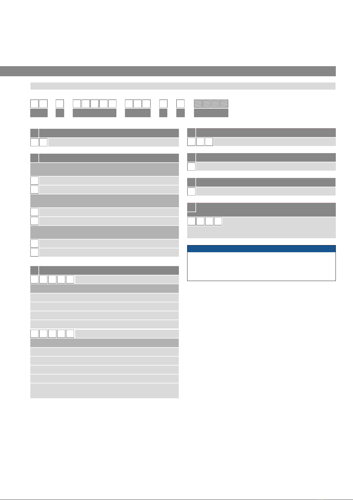
3.1 Order code of Temposonics®EH
3. Identification
a Sensor model
E H Rod
b Design
EH rod-style sensor with housing material 1.4305 (AISI 303)
and rod material 1.4301 (AISI 304)
KThreaded fl ange M18×1.5-6g, Ø 7 mm rod
LThreaded fl ange ¾" - 16 UNF -3A, Ø 7 mm rod
EH rod-style sensor with housing material 1.4305 (AISI 303)
and rod material 1.4306 (AISI 304L)
MThreaded fl ange M18×1.5-6g, Ø 10 mm rod
SThreaded fl ange ¾"- 16 UNF -3A, Ø 10 mm rod
EH rod-style sensor with housing material 1.4404 (AISI 316L)
and rod material 1.4404 (AISI 316L)
FThreaded flange ¾"-16 UNF-3A, Ø 10 mm rod
WThreaded flange M18×1.5-6g, Ø 10 mm rod
c Stroke length
X X X X M 0050…2540 mm
Standard stroke length (mm) Ordering steps
50… 500 mm 5 mm
500… 750 mm 10 mm
750…1000 mm 25 mm
1000…2540 mm 50 mm
X X X X U001.0…100.0 in.
Standard stroke length (in.) Ordering steps
1… 20 in. 0.2 in.
20… 30 in. 0.4 in.
30… 40 in. 1.0 in.
40…100 in. 2.0 in.
Non-standard stroke lengths are available;
must be encoded in 5 mm/0.1 in. increments.
.
dConnection type
D4 4 M12 male connector (4 pin)
dConnection type
D4 4 M12 male connector (4 pin)
eOperating voltage
1+24 VDC (±25 %)
eOperating voltage
1+24 VDC (±25 %)
f Output
KIO-Link
f Output
KIO-Link
g
Advanced single-position measurement or multi-position
measurement (optional)
1Z 0 X Number of magnets
01…04 position and velocity (1…4 magnet(s))
01…08 position (1…8 magnet(s))
g
Advanced single-position measurement or multi-position
measurement (optional)
1Z 0 X Number of magnets
01…04 position and velocity (1…4 magnet(s))
01…08 position (1…8 magnet(s))
1 2 3 4 5 6 7 8 9 10 11 12 13 14 15 16 17
E H D 4 4 1K
a b c d e f g
optional
NOTICE
• The number of magnets is limited by the stroke length. The mini-
mum allowed distance between magnets (i.e. front face of one to
the front face of the next one) is 75 mm (3 in.).
• Use magnets of the same type for multi-position measurement.
NOTICE
• The number of magnets is limited by the stroke length. The mini-
mum allowed distance between magnets (i.e. front face of one to
the front face of the next one) is 75 mm (3 in.).
• Use magnets of the same type for multi-position measurement.
Temposonics® E-Series IO-Link
Operation Manual
I 6 I
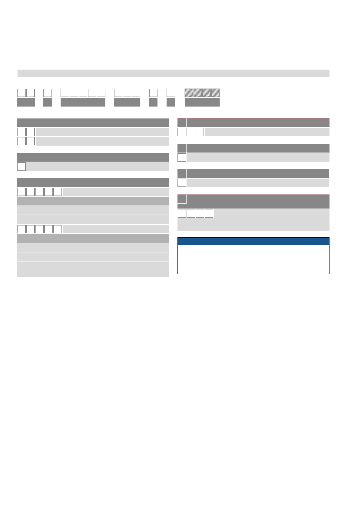
3.2 Order code of Temposonics® EP/EL
dConnection type
D4 4 M12 male connector (4 pin)
dConnection type
D4 4 M12 male connector (4 pin)
eOperating voltage
1+24 VDC (±25 %)
eOperating voltage
1+24 VDC (±25 %)
f Output
KIO-Link
f Output
KIO-Link
gAdvanced single-position measurement or multi-position
measurement (optional)
1Z 0 X Number of magnets
01…04 position and velocity (1…4 magnet(s))
01…08 position (1…8 magnet(s))
gAdvanced single-position measurement or multi-position
measurement (optional)
1Z 0 X Number of magnets
01…04 position and velocity (1…4 magnet(s))
01…08 position (1…8 magnet(s))
a Sensor model
E P Ultra low pro le
E L Compact pro le
b Design
0Without position magnet
c Stroke length
X X X X M 0050…2540 mm
Standard stroke length (mm) Ordering steps
50… 500 mm 25 mm
500…2540 mm 50 mm
X X X X U001.0…100.0 in.
Standard stroke length (in.) Ordering steps
1… 20 in. 1.0 in.
20…100 in. 2.0 in.
Non-standard stroke lengths are available;
must be encoded in 5 mm/0.1 in. increments.
.
1 2 3 4 5 6 7 8 9 10 11 12 13 14 15 16 17
E0D 4 4 1K
a b c d e f g
optional
NOTICE
• The number of magnets is limited by the stroke length. The mini-
mum allowed distance between magnets (i.e. front face of one to
the front face of the next one) is 75 mm (3 in.).
• Use magnets of the same type for multi-position measurement.
Temposonics® E-Series IO-Link
Operation Manual
I 7 I
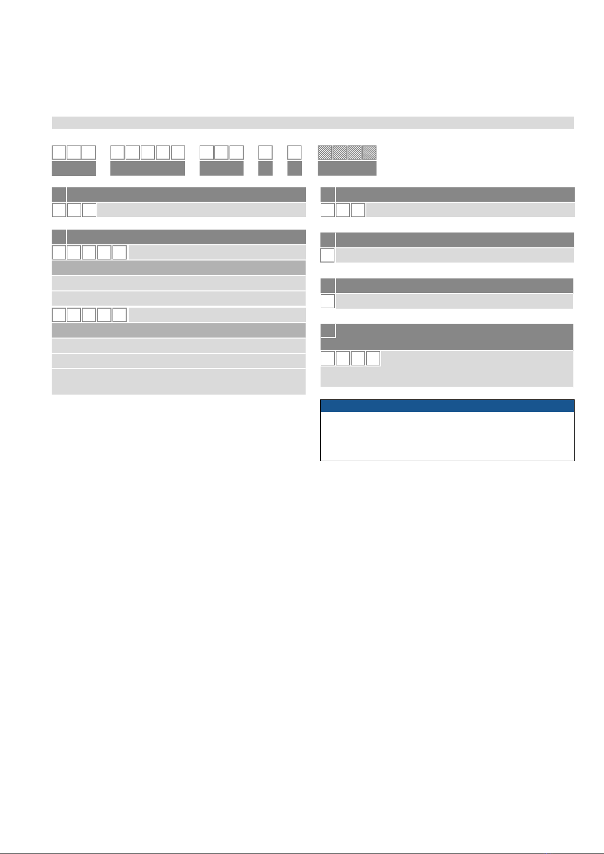
3.3 Order code of Temposonics® EP2
c Connection type
D 4 4 M12 (4 pin) male connector
d Operating voltage
1+24 VDC (±25 %)
e Output
KIO-Link
1 2 3 4 5 6 7 8 9 10 11 12 13 14 15 16 17
E P 2D 4 4 1K
a b c d e f
f Advanced single-position measurement or
multi-position measurement (optional)
1Z 0 X Number of magnets
01…04 position and velocity (1…4 magnet(s))
01…08 position (1…8 magnet(s))
a Sensor model
E P 2 Smooth pro le
b Stroke length
X X X X M 0050…2540 mm
Standard stroke length (mm) Ordering steps
50… 500 mm 25 mm
500…2540 mm 50 mm
X X X X U 001.0…128.0 in.
Standard stroke length (in.) Ordering steps
2… 20 in. 1.0 in.
20…100 in. 2.0 in.
Non-standard stroke lengths are available;
must be encoded in 5 mm/0.1 in. increments.
.
NOTICE
• The number of magnets is limited by the stroke length.
The minimum allowed distance between magnets (i.e. front face
of one to the front face of the next one) is 75 mm (3 in.).
• Use magnets of the same type for multi-position measurement.
Temposonics® E-Series IO-Link
Operation Manual
I 8 I
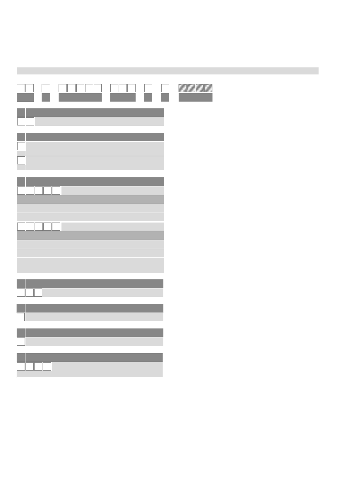
3.4 Order code of Temposonics® ER
d Connection type
D 4 4 M12 (4 pin) male connector
e Operating voltage
1+24 VDC (±25 %)
f Output
KIO-Link
1 2 3 4 5 6 7 8 9 10 11 12 13 14 15 16 17
E R D 4 4 1K
a b c d e f g
gAdvanced single-position measurement
1 Z 0 1 Number of magnets
1 position and velocity (1 magnet)
aSensor model
E R Aluminum cylinder with a guided driving rod
b Design
MInside thread M6 at end of rod
(For metric stroke length measurement)
SInside thread ¼"-28 UNF at end of rod
(For US customary stroke length measurement)
c Stroke length
X X X X M 0050…1500 mm
Standard stroke length (mm) Ordering steps
50…500 mm 25 mm
500…1500 mm 50 mm
X X X X U002.0…060.0 in.
Standard stroke length (in.) Ordering steps
2…22 in. 1.0 in.
22…60 in. 2.0 in.
Non-standard stroke lengths are available;
must be encoded in 5 mm/0.1 in. increments.
.

Temposonics® E-Series IO-Link
Operation Manual
I 9 I
3.5 Nameplate
3.6 Approvals
• CE certified
• UKCA certified
• EAC certified
• UL certified
• Metrology certificate of Kazakhstan
Fig.1: Example of nameplate of an E-Series EH sensor
NOTICE
For a detailed overview of the certications, see
www.temposonics.com
E
E-Series
temposonics.com
EHM0200MD441K
S/N: 70008887
Sensor model
Part No.
Serial number
Stroke length (e.g. 200 mm)
Output
Connection type
Operating voltage
3.7 Scope of delivery
EH (rod sensor):
• Sensor
• O-ring
EP (compact profile sensor):
• Sensor
• 2 mounting clamps up to 1250 mm (50 in.) stroke length +
1 mounting clamp for each 500 mm (20 in.) additional stroke length
EL (ultra low profile sensor):
• Sensor
• 2 mounting clamps up to 1250 mm (50 in.) stroke length +
1 mounting clamp for each 500 mm (20 in.) additional stroke length
EP2 (smooth profile sensor):
• Sensor
• 2 mounting clamps up to 1250 mm (50 in.) stroke length +
1 mounting clamp for each 500 mm (20 in.) additional stroke length
ER (aluminum cylinder with a guided driving rod sensor):
• Sensor

Temposonics® E-Series IO-Link
Operation Manual
I 10 I
4.1 Functionality and system design
Product designation
• Position sensor Temposonics®E-Series
Sensor model
• Temposonics®EH (rod sensor)
• Temposonics®EP (compact profile sensor)
• Temposonics®EP (ultra low profile sensor)
• Temposonics®EP2 (smooth profile sensor)
• Temposonics®ER (aluminum cylinder with a guided driving
rod sensor)
Stroke length
• EH 50…2540 mm (2…100 in.)
• EP 50…2540 mm (2…100 in.)
• EL 50…2540 mm (2…100 in.)
• EP2 50…2540 mm (2…100 in.)
• ER 50…1500 mm (2…60 in.)
Output signal
• IO-Link
Application
The Temposonics position sensors are used for measurement and
conversion of the length (position) variable in the fields of automated
systems and mechanical engineering.
Principle of operation and system construction
4. Product description and commissioning
4
5
3
1
Measurement cycle
1Current pulse generates magnetic eld
2Interaction with position magnet eld
generates torsional strain pulse
3Torsional strain pulse propagates
4Strain pulse detected by converter
5Time-of-fl ight converted into position
Sensing element (Waveguide)
Position magnet (Magnetic eld)
Torsional strain pulse converter
2
Fig.2: Time-of-flight based magnetostrictive position sensing principle
Modular mechanical and electronic construction
• The sensor rod or profile protects the inner sensor element.
• The sensor electronics housing, a rugged construction, contains
the complete electronic interface with active signal conditioning.
• The external position magnet is a permanent magnet. Mounted on
the mobile machine part, it travels along the sensor rod or profile
and triggers the measurement through the sensor rod wall.
• The sensor can be connected directly to a control system.
Its electronics generates a strictly position proportional signal
output between start and end position.
MEASURING TECHNOLOGY
The absolute, linear position sensors provided by Temposonics rely on
the company’s proprietary magnetostrictive technology, which can
determine position with a high level of precision and robustness.
Each Temposonics position sensor consists of a ferromagnetic
waveguide, a position magnet, a strain pulse converter and a supporting
electronics. The magnet, connected to the object in motion in the
application, generates a magnetic eld at its location on the waveguide.
A short current pulse is applied to the waveguide. This creates a
momentary radial magnetic eld and torsional strain on the waveguide.
The momentary interaction of the magnetic elds releases a torsional
strain pulse that propagates the length of the waveguide. When the
ultrasonic wave reaches the beginning of the waveguide it is converted
into an electrical signal. Since the speed of the ultrasonic wave in the
waveguide is precisely known, the time required to receive the return
signal can be converted into a linear position measurement with both
high accuracy and repeatability.
Temposonics® E-Series IO-Link
Operation Manual
I 11 I
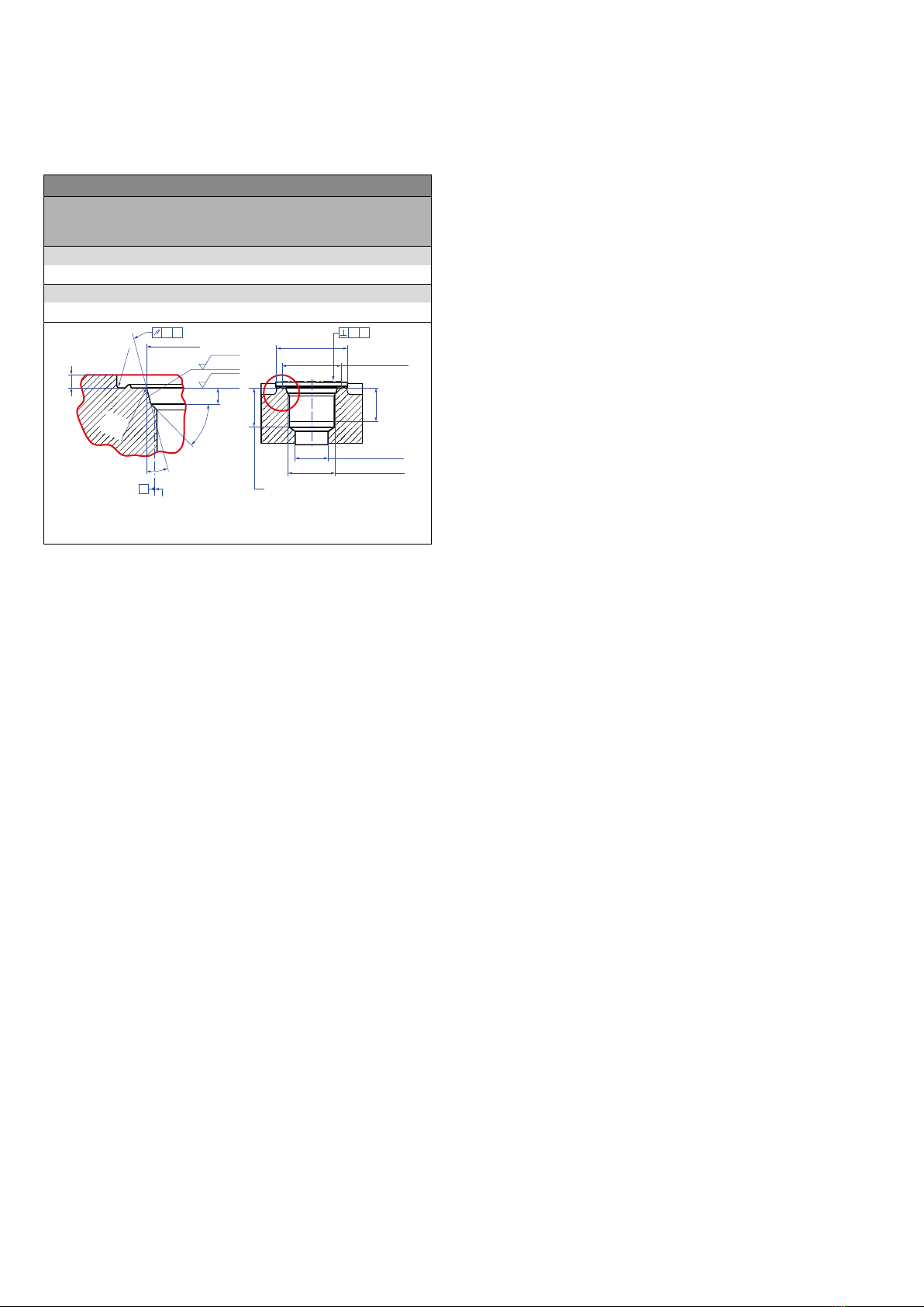
Hydraulics sealing
The flange contact surface is sealed via an O-ring in the undercut
(Fig.46).
For threaded flange (¾"-16 UNF-3A) »F« / »L« / »S«:
O-ring 16.4 × 2.2 mm (0.65 × 0.09 in.) (part no. 560315)
For threaded flange (M18×1.5-6g) »K« / »M« / »W«:
O-ring 15.3 × 2.2 mm (0.60 × 0.09 in.) (part no. 401133)
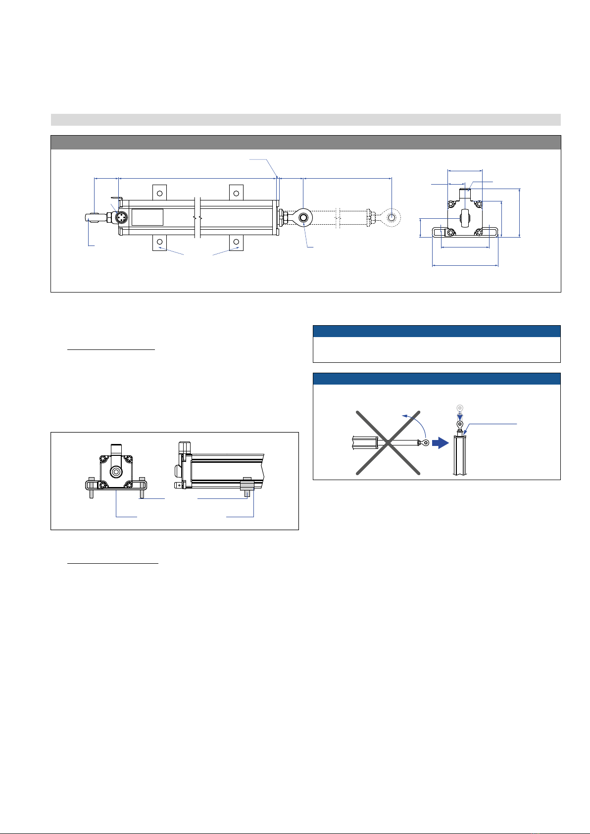
4.2 Styles and installation of Temposonics® EH
• Note the fastening torque of 50 Nm.
• Seat the flange contact surface completely on the cylinder
mounting surface.
• The cylinder manufacturer determines the pressure-resistant
gasket (copper gasket, O-ring, etc.).
• The position magnet should not grind on the sensor rod.
• The piston rod drilling
(EH-K/-L: Ø 7 mm rod: ≥ Ø 10 mm (≥ Ø 0.40 in.);
EH-M/-S/-F/-W: Ø 10 mm rod: ≥ Ø 13 mm (≥ Ø 0.52 in.))
depends on the pressure and piston speed.
• Adhere to the information relating to operating pressure.
• Protect the sensor rod against wear.
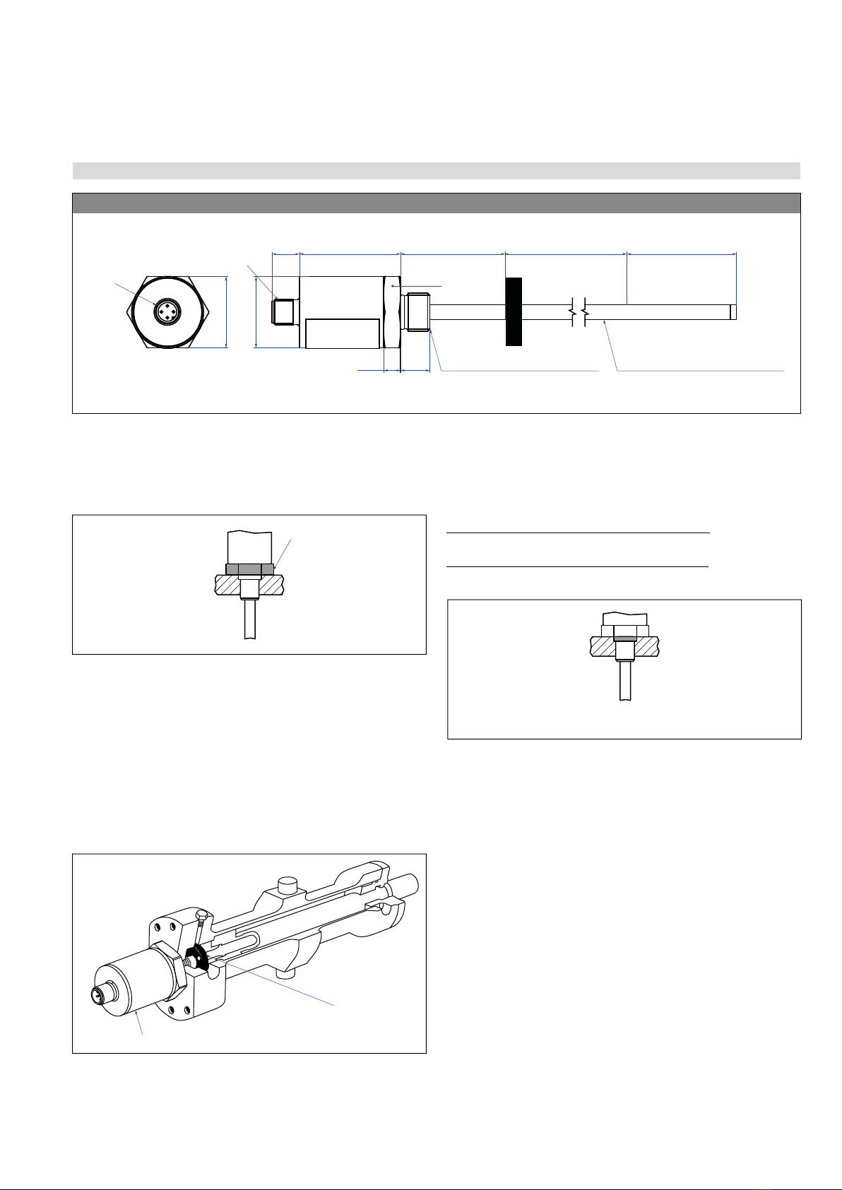
Installation of EH with threaded flange
Fix the sensor rod via threaded flange M18×1.5-6g or ¾"-16 UNF-3A.
Fig.3: Temposonics®EH sensor
Fig.4: Mounting example of threaded flange
Installation of a rod-style sensor in a fluid cylinder
The rod-style version has been developed for direct stroke
measurement in a fluid cylinder. Mount the sensor via threaded flange
or a hex nut.
• Mounted on the face of the piston, the position magnet travels
over the rod without touching it and indicates the exact position
through the rod wall – independent of the hydraulic fluid.
• The pressure resistant sensor rod is installed into a bore in the
piston rod.
Fig.5: Sensor in cylinder
In the case of threaded flange M18×1.5-6g, a screw hole based on
ISO 6149-1 (Fig.7) must be provided. See ISO 6149-1 for further
information.
Fig.6: Possibility of sealing
EH with threaded fl ange M18×1.5-6g or ¾"-16 UNF-3A
Magnet
M12
Ø 34
(Ø 1.34)
A/F 34
Sensor electronics housing
48
(1.89)
13
(0.51)
Dead zone
63.5
(2.5)
Stroke length
50…2540
(2…100)
8
(0.31)
Sensor rod: Ø 7 ± 0.10 (Ø 0.28 ± 0.01)
Sensor rod: Ø 10 ± 0.13 (Ø 0.39 ± 0.01)
Null zone
51
(2.01)
14
(0.55)
A/F 34
Flange »K«, »M«, »W«: M18×1.5-6g
Flange »F«, »L«, »S«: ¾"-16 UNF-3A
4 pin
Controlling design dimensions are in millimeters and measurements in ( ) are in inches
Fastening torque
50 Nm
Sealing via O-ring
in the flange undercut
Position magnet
Sensor electronics housing
Temposonics® E-Series IO-Link
Operation Manual
I 12 I
Fig.7: Notice for metric threaded flange M18×1.5-6g based on DIN ISO 6149-1
Notice for metric threaded fl anges
Thread
(d1×P)
d2d3d4d5
+0.1
0
L1
+0.4
0
L2L3L4Z°
±1°
EH-K (Ø 7 mm rod)
M18×1.5-6g 55 ≥ 10 24.5 19.8 2.4 28.5 2 26 15°
EH-M/-W (Ø 10 mm rod)
M18×1.5-6g 55 ≥ 13 24.5 19.8 2.4 28.5 2 26 15°
Ød
5
Ra 3.2
Ra 3.2
Pitch diameter
A
A
Thread
(d
1
× P)
Ød
3
(Reference)
A
Ød
2
Ød
4
(Gauging)
This dimension applies when
tap drill cannot pass through
entire boss.
≤ R0.4
R0.3
R0.1
Z°
4
5
°
±
5
°
L
3
L
1
L
2
L
4
A0.1 A0.2
Controlling design dimensions are in millimeters
Temposonics® E-Series IO-Link
Operation Manual
I 13 I
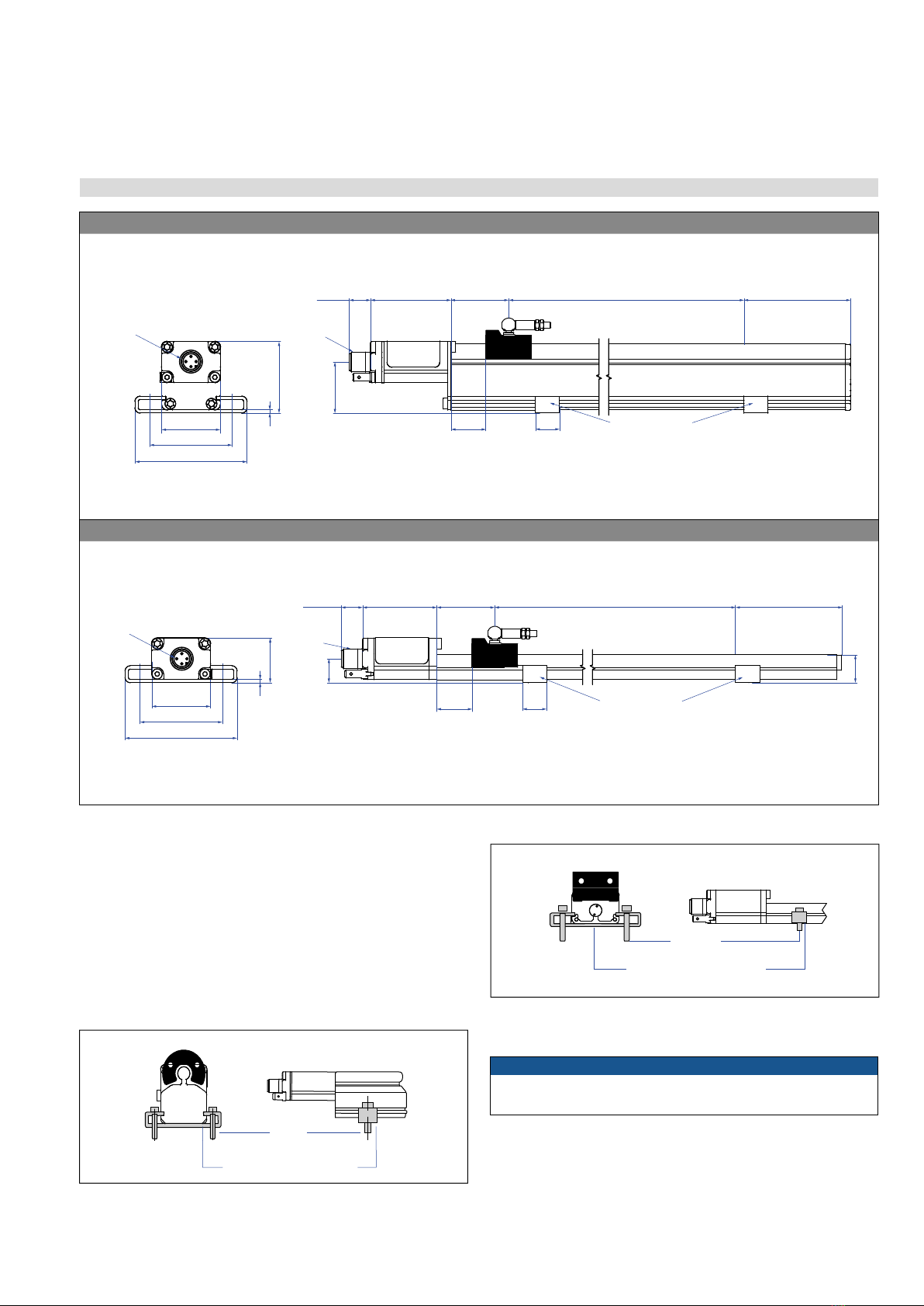
4.3 Styles and installation of Temposonics® EP/EL
Fig.8: E-Series EP and EL with magnet slider
Installation of EP/EL
The position sensor can be installed in any position. Normally,
the sensor is firmly installed and the position magnet is fastened
to the mobile machine part. Thus it can travel along the measuring
rod without touching it. The sensor is fitted on a flat machine surface
using the mounting clamps (Fig.9). A length-dependent number of
these clamps are delivered with the sensor and must be distributed
over the profile at regular distances. For fastening use M5×20 screws
to DIN 6912 that should be tightened with a fastening torque of 5 Nm.
Fig.9: EP with mounting clamps with cylinder screw M5×20 (part no. 403 508)
Fig.10: EL with mounting clamps with cylinder screw M5×20 (part no. 403 508)
NOTICE
Take care to mount the sensor in an axially parallel position to
avoid damage of the carriage, magnet and sensor rod.
Adjustable mounting clamps
M5×20
Fastening torque: 5 Nm
Adjustable mounting clamps
M5×20
max. 5 Nm
EP
Magnet
4 pin M12
50 (1.97)
68 (2.68)
14.6
(0.57)
31
(1.22)
41
(1.61)
35.6 (1.40)
Sensor
electronics
housing
48.8
(1.92)
13
(0.51)
Stroke length
50…2540
(2…100)
Dead zone
68
(2.68)
Null zone
35
(1.38)
2 (0.08)
Mounting clamps
*Measuring start
Magnet slider S: 19 (0.75)
Magnet slider V: 19 (0.75)
U-magnet OD33: 35 (1.38)
Block magnet L: 32.5 (1.28)
*
EL
Magnet
M12
Sensor
electronics
housing
45
(1.77)
13
(0.51)
14.6
(0.57)
Stroke length
50…2540
(2…100)
Dead zone
68
(2.68)
17
(0.67)
27
(1.06)
2 (0.08)
35.6 (1.40)
68 (2.68)
50 (1.97)
14.5
(0.57)
4 pin
Null zone
35
(1.38)
Mounting clamps
*
*Measuring start:
Magnet slider S: 19 (0.75)
Magnet slider V: 19 (0.75)
Block magnet L: 32.5 (1.28)
Controlling design dimensions are in millimeters and measurements in ( ) are in inches
Temposonics® E-Series IO-Link
Operation Manual
I 14 I
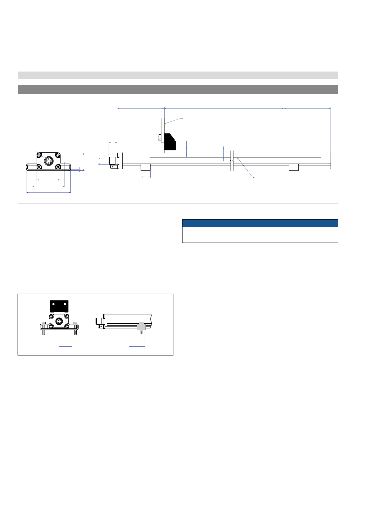
4.4 Styles and installation of Temposonics® EP2
Fig.11: Temposonics EP2
Fig.12: Mounting clamps with cylinder screw M5×20 (part no. 403 508)
NOTICE
Take care to mount the sensor in an axially parallel position to
avoid damage of the carriage, magnet and sensor rod.
Installation of EP2
The position sensor can be installed in any position. Normally,
the sensor is firmly installed and the position magnet is fastened
to the mobile machine part. Thus it can travel along the measuring
rod without touching it. The sensor is fitted on a flat machine surface
using the mounting clamps (Fig.12). A length-dependent number of
these clamps are delivered with the sensor and must be distributed
over the profile at regular distances. For fastening use M5×20 screws
to DIN 6912 that should be tightened with a fastening torque of 5 Nm.
EP2
Magnet
Magnet
Stroke length
50…2540
(2…100)
M12
Null zone
73
(2.87)
13
(0.51)
14.6
(0.57)
Dead zone
73
(2.87)
27
(1.06)
2 (0.08)
35.6 (1.40)
68 (2.68)
50 (1.97)
4 pin
Mounting support
3 ± 2 (0.12 ± 0.08)
8 ± 2 (0.31 ± 0.08)
Sensing element
inside the sensor
Controlling design dimensions are in millimeters and measurements in ( ) are in inches
Adjustable mounting clamps
M5×20
Fastening torque: 5 Nm
Temposonics® E-Series IO-Link
Operation Manual
I 15 I
4.5 Styles and installation of Temposonics® ER
Fig.13: Temposonics ER
Fig.14: Mounting clamps with cylinder screw M5×20 (part no. 403 508)
NOTICE
Take care to mount the sensor in an axially parallel position to
avoid damage of the carriage and sensor rod.
NOTICE
Do not raise up the ER sensor, if the lifting rod is extended.
It causes
serious damage
There are two ways to install the sensor ER:
1. Via the mounting clamps
The position sensor can be installed in any position. The sensor
is fitted on a flat machine surface using the mounting clamps
(Fig.14). A length-dependent number of must be distributed over
the profile at regular distances. For fastening use M5×20 screws
to DIN 6912 that should be tightened with a fastening torque of
5 Nm.
2. Via the adjustable rod end
The position sensor can be installed in any position.
The sensor is mechanically connected via adjustable rod ends
(for ER-M: part no. 254 210 / for ER-S: part no. 254 235)
ER
50
(1.97)
51
(2.01)
Stroke length
50…1500
(2…60)
M12×1
37.8
(1.49)
68
(2.68)
17.8
(0.7)
20
(0.79)
25
(1)
25
(1)
Optional:
Adjustable
rod end M6 /
¼"-28 UNF
Optional:
Adjustable
rod end M6 /
¼"-28 UNF
4 pin
Optional:
Mounting clamps
132.5 + stroke length
(5.22 + stroke length)
35.5
(1.40)
3
(0.12)
Controlling design dimensions are in millimeters and measurements in ( ) are in inches
Adjustable mounting clamps
M5×20
Fastening torque: 5 Nm
Temposonics® E-Series IO-Link
Operation Manual
I 16 I
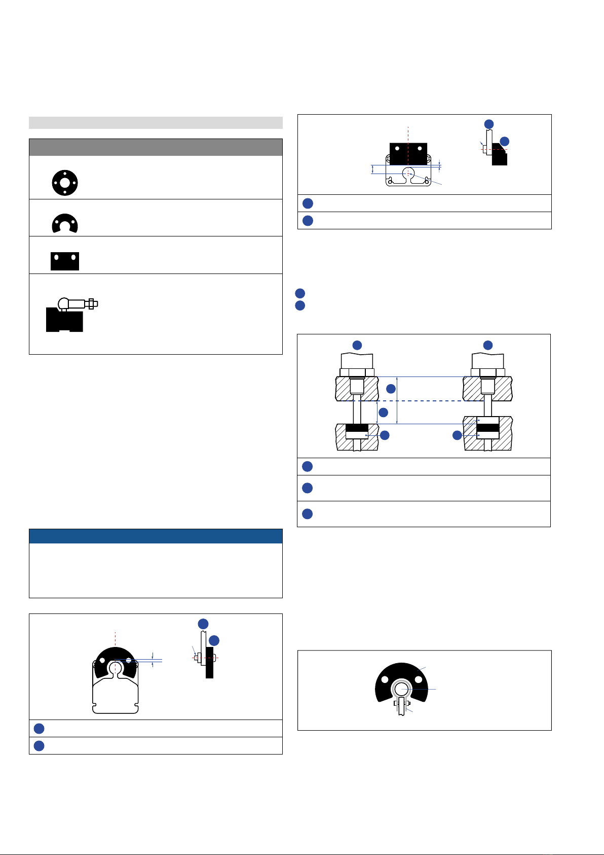
4.6 Magnet installation
Sensors with stroke lengths ≥ 1 meter (3.3 ft.)
Support horizontally installed sensors with a stroke length from
1 meter (3.3 ft.) mechanically at the rod end. Without the use
of a support, rod and position magnet may be damaged. A false
measurement result is also possible. Longer rods require evenly
distributed mechanical support over the entire length (e.g. part no.
561 481). Use an U-magnet (Fig.19) for measurement.
NOTICE
Mount ring magnets and U-magnets concentrically.
Mount block magnets centrically over the sensor rod or the sensor
profile. Do not exceed the maximum acceptable gap (Fig.16,
Fig.17).
Controlling design dimensions are in millimeters and measurements in ( ) are in inches
Fig. 15: Typical use of magnets
Mounting the ring magnets, U-magnets & block magnets
Install the magnet using non-magnetic material for mounting
device, screws, spacers etc.. The magnet must not grind on
the sensor rod. Alignment errors are compensated via the air gap.
• Permissible surface pressure: Max. 40 N/mm2 (only for ring
magnets and U-magnets)
• Fastening torque for M4 screws: 1 Nm; use washers, if necessary
• Minimum distance between position magnet and any magnetic
material has to be 15 mm (0.6 in.) (Fig.18).
• If no other option exists and magnetic material is used,
observe the specified dimensions (Fig.18).
Magnet mounting with magnetic material
When using magnetic material the dimensions of Fig.18 must
be observed.
A If the position magnet aligns with the drilled piston rod
B If the position magnet is set further into the drilled piston rod,
install another non-magnetic spacer above the magnet.
Fig.16: Mounting of U-magnet (part no. 251 416-2), example of EP sensor
Fig.17: Mounting of block magnet (part no. 403 448), example of EL sensor
Fig.18: Installation with magnetic material
Fig.19: Example of sensor support (part no. 561 481)
M4 1
2
Air gap:
1.75 ±1
1U-magnet
2Non-magnetic mounting plate
M4
2
1
8 ±2
(0.31 ±0.08) Sensing element
Air gap: 3 ±2
(0.12 ±0.08)
1Block magnet
2Non-magnetic mounting plate
Magnet Magnet
1
2
3
A B
Magnetic
material
3
1Null zone, depends on sensor model
2Distance between position magnet and any magnetic material
(≥ 15 mm (≥ 0.6 in.))
3Non-magnetic spacer (≥ 5 mm (≥ 0.2 in.)) –
Recommendation: 8 mm (0.31 in.)
U-magnet
Sensor rod
Non-magnetic fixing clip
Magnet Typical sensors Benefi ts
Ring magnets Rod model
(EH)
• Rotationally symmetrical
magnetic eld
U-magnets Profi le &
rod models
(EH, EP)
• Height tolerances can be
compensated, because the
magnet can be lifted off
Block magnets Profi le &
rod models
(EH, EP, EL, EP2)
• Height tolerances can be
compensated, because the
magnet can be lifted off
Magnet sliders Profi le models
(EP, EL)
• The magnet is guided by
the pro le
• The distance between the
magnet and the waveguide
is strictly de ned
• Easy coupling via the
ball joint

Temposonics® E-Series IO-Link
Operation Manual
I 17 I
Start and end positions of the position magnets
Consider the start and end positions of the position magnets during
the installation. To ensure that the entire stroke length is electrically
usable, the position magnet must be mechanically mounted as
follows.
Fig.20: Start- and end positions of magnets, part 1
Fig.21: Start- and end positions of magnets, part 2
Controlling design dimensions are in millimeters and measurements in ( ) are in inches
Multi-position measurement
The minimum distance between the magnets is 75 mm (3 in.).
EH with ring magnets/U-magnets
≥75 (≥ 3)
EH with block magnets
≥75 (≥ 3)
EP with magnet sliders
≥75 (≥ 3)
EP with U-magnets
≥75 (≥ 3)
EP with block magnets
≥75 (≥ 3)
EL with magnet sliders
≥75 (≥ 3)
EL with block magnets
≥75 (≥ 3)
EP2 with block magnets
≥75 (≥ 3)
E-Series EH with ring- / U-magnet
Start position
51 (2.01)
End position
63.5 (2.5)
E-Series EH with block magnet
Start position
48.5 (1.91)
End position
66 (2.6)
E-Series EP with magnet slider “S”, “N”, “V”, “G”
Start position
19 (0.75)
End position
84 (3.3)
E-Series EP with U-magnet
Start position
35 (1.38)
End position
68 (2.68)
E-Series EP with block magnet
Start position
32.5 (1.29)
End position
70.5 (2.78)
E-Series EL with magnet slider “S”, “N”, “V”, “G”
Start position
19 (0.75)
End position
84 (3.3)
E-Series EL with block magnet
Start position
32.5 (1.29)
End position
70.5 (2.78)
E-Series EP2 with block magnet
Start position
73 (2.87)
End position
73 (2.87)
Fig.22: Minimum distance for multi-position measurement
Temposonics® E-Series IO-Link
Operation Manual
I 18 I
4.7 Electrical connections
Placement of installation and cabling have decisive influence on
the sensor‘s electromagnetic compatibility (EMC). Hence correct
installation of this active electronic system and the EMC of the
entire system must be ensured by using suitable metal connectors,
shielded* cables and grounding. Overvoltages or faulty connections
can damage its electronics despite protection against wrong polarity.
Instructions for connection
• Use low-resistant twisted pair and shielded cables. Connect
the shield to ground externally via the controller equipment.
• Keep control and sign leads separate from power cables and
sufficiently far away from motor cables, frequency inverters,
valve lines, relays, etc..
• Use only connectors with metal housing and connect the shielding
to the connector housing.
• Keep the connection surface at both shielding ends as large
as possible. Connect the cable clamps to function as a ground.
• Keep all non-shielded leads as short as possible.
• Keep the earth connection as short as possible with a large
cross section. Avoid ground loops.
• With potential differences between machine and electronics earth
connections, no compensating currents are allowed to flow across
the cable shielding.
Recommendation:
Install potential compensating leads with large cross section or use
cables with separate double shielding, and connect only one end of
the shield.
• Use only stabilized power supplies in compliance with the specified
connecting values.
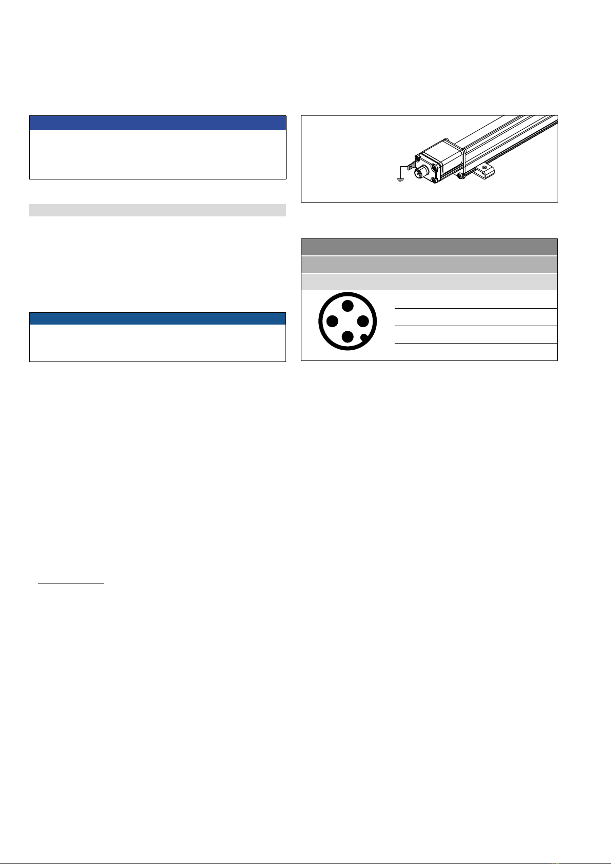
Grounding of profile and rod sensors
Connect the sensor electronics housing to machine ground. Ground
sensor types EP, EL, EP2 and ER via ground lug as shown in Fig.23.
The sensor type EH is grounded via thread.
*/ The use of shielded cables is a recommendation of Temposonics to afford a better
protection against signal disturbances
NOTICE
1. Do not mount the sensors in the area of strong magnetic or
electric noise fields.
2. Never connect/disconnect the sensor when voltage is applied.
Fig.23: Grounding via ground lug e.g. profile sensor
Fig.24: Connector wiring D44
D44
Signal + power supply
M12 male connector Pin Function
2
1
4
3
View on sensor
1 +24 VDC (−15/+20 %)
2 DI/DQ
3 DC Ground (0 V)
4 C/Q
NOTICE
For multi-position measurement, use magnets of the same type.
Do not fall below the minimum distance between the magnets of
75mm (3 in.) for multi-position measurement. Contact Temposonics
if you need a magnet distance < 75 mm (3 in.).

Temposonics® E-Series IO-Link
Operation Manual
I 19 I
4.8 Frequently ordered accessories
Position magnets
Ø 32.8
(Ø 1.29)
Ø 23.8
(Ø 0.94)
Ø 13.5
(Ø 0.53)
Ø 4.3
(Ø
0.17)
7.9
(0.31)
Ø 25.4
(
Ø
1)
Ø 13.5
(
Ø
0.53) 7.9
(0.31)
Ø 13.5
(Ø 0.53)
Ø 17.4
(Ø 0.69)
7.9
(0.31)
Ø 32.8
(Ø 1.29)
Ø 23.8
(Ø 0.94)
Ø 13.5
(Ø 0.53)
Ø 4.3
(Ø 0.17)
60°
140°
3
(0.12)
7.9
(0.31)
Ring magnet OD33
Part no. 201 542-2
Ring magnet OD25.4
Part no. 400 533
Ring magnet OD17.4
Part no. 401 032
U-magnet OD33
Part no. 251 416-2
Material: PA ferrite GF20
Weight: Approx. 14 g
Surface pressure: Max. 40 N/mm2
Fastening torque for M4 screws: 1 Nm
Operating temperature:
−40…+105 °C (−40…+221 °F)
Material: PA ferrite
Weight: Approx. 10 g
Surface pressure: Max. 40 N/mm2
Operating temperature:
−40…+105 °C (−40…+221 °F)
Material: PA neobond
Weight: Approx. 5 g
Surface pressure: Max. 20 N/mm2
Operating temperature:
−40…+105 °C (−40…+221 °F)
Material: PA ferrite GF20
Weight: Approx. 11 g
Surface pressure: Max. 40 N/mm2
Fastening torque for M4 screws: 1 Nm
Operating temperature:
−40…+105 °C (−40…+221 °F)
Position magnets
Ø 19.8
(Ø 0.78)
Ø 30.5
(Ø 1.2)
7.6
(0.3)
M5
20
(0.79)
43
(1.69)
14
(0.55)
17.2 (0.67)
40 (1.57)
18°
25.3 (1)
40 (1.57)
18°
57 (2.24) 14
(0.55)
25.3 (1)
8.2 (0.32)
49 (1.93)
M5
19.5 (0.77)
1.5
(0.06)
33 (1.3)
14
(0.55)
20.5
(0.81)
14.9 (0.59)
8 ± 2 (0.31 ± 0.08)
Distance to sensor element
Ø 4.3
(Ø 0.17)
Ring magnet
Part no. 402 316
Magnet slider S, joint at top
Part no. 252 182
Magnet slider V, joint at front
Part no. 252 184
Block magnet L
Part no. 403 448
Material: PA ferrite coated
Weight: Approx. 13 g
Surface pressure: Max. 20 N/mm2
Operating temperature:
−40…+100 °C (−40…+212 °F)
Material: GRP, magnet hard ferrite
Weight: Approx. 35 g
Operating temperature:
−40…+85 °C (−40…+185 °F)
Material: GRP, magnet hard ferrite
Weight: Approx. 35 g
Operating temperature:
−40…+85 °C (−40…+185 °F)
Material: Plastic carrier with hard ferrite
magnet
Weight: Approx. 20 g
Fastening torque for M4 screws: 1 Nm
Operating temperature:
−40…+75 °C (−40…+167 °F)
This magnet may infl uence the sensor
performance speci cations for some
applications.
Magnet spacer Sealing
Ø 14.3
(Ø 0.56)
Ø 23.8
(Ø 0.94)
Ø 31.8
(Ø 1.25)
Ø 4.3
(Ø 0.17)
3.2
(0.13)
Ø 15.3
(Ø 0.6)
Ø 2.2
(Ø 0.09)
Ø 16.4
(Ø 0.65)
Ø 2.2
(Ø 0.09)
Magnet spacer
Part no. 400 633
O-ring for threaded fl ange
M18×1.5-6g
Part no. 401 133
O-ring for threaded fl ange
¾"-16 UNF-3A
Part no. 560 315
Material: Aluminum
Weight: Approx. 5 g
Surface pressure: Max. 20 N/mm2
Fastening torque for M4 screws: 1 Nm
Material: Fluoroelastomer
Durometer: 75 ± 5 Shore A
Operating temperature:
−40…+204 °C (−40…+400 °F)
Material: Fluoroelastomer
Durometer: 75 ± 5 Shore A
Operating temperature:
−40…+204 °C (−40…+400 °F)
– Additional options available in our Accessories Guide 551 444
Controlling design dimensions are in millimeters and measurements in ( ) are in inches

Temposonics® E-Series IO-Link
Operation Manual
I 20 I
3/ Follow the manufacturer‘s mounting instructions
Controlling design dimensions are in millimeters and measurements in ( ) are in inches
Color of connectors and cable jacket may change. Colors of the cores and technical properties remain unchanged.
Cable connectors 3Cables
53
(2.09)
Ø 20
(
Ø 0.79)
38
(1.5)
Ø 20
(Ø 0.79)
57
(2.25)
M12 A-coded female connector
(4 pin/5 pin), straight
Part no. 370 677
M12 A-coded female connector
(5 pin), angled
Part no. 370 678
Cable with M12 A-coded female
connector (5 pin), straight – pigtail
Part no. 370 673
Cable with M12 A-coded female
connector (5 pin), angled – pigtail
Part no. 370 675
Material: GD-Zn, Ni
Termination: Screw
Contact insert: CuZn
Cable Ø: 4…8 mm (0.16…0.31 in.)
Wire: 1.5 mm²
Operating temperature:
−30…+85 °C (−22…+185 °F)
Ingress protection: IP67 (correctly tted)
Fastening torque: 0.6 Nm
Material: GD-Zn, Ni
Termination: Screw; max. 0.75 mm²
Contact insert: CuZn
Cable Ø: 5…8 mm (0.2…0.31 in.)
Wire: 0.75 mm2 (18 AWG)
Operating temperature:
−25…+85 °C (−13…+185 °F)
Ingress protection: IP67 (correctly tted)
Fastening torque: 0.4 Nm
Material: PUR jacket; black
Features: Shielded
Cable length: 5 m (16.4 ft)
Ingress protection: IP67 (correctly tted)
Operating temperature:
−25…+80 °C (−13…+176 °F)
Material: PUR jacket; black
Features: Shielded
Cable length: 5 m (16.4 ft)
Ingress protection: IP67 (correctly tted)
Operating temperature:
−25…+80 °C (−13…+176 °F)
Hex nut Mounting hardware Mounting clamp
M18×1.5-6g
A/F 27
8.7
(0.34)
¾"-16 UNF-3A
A/F 28
11
(0.43)
20 (0.79)
60 (2.36)
16 (0.63)
12 (0.47)
3.2 (0.13)
Ø 3.2 (Ø 0.13)
M3 fastening screws (6×)
4 Holes
Ø 5.4 (Ø 0.21) 31 (1.22) 9 (0.35)
50 (1.97)
2 (0.08)
68 (2.68)
10 (0.39)
Mounting clamp width:
14.6 (0.57)
Hex jam nut M18×1.5-6g
Part no. 500 018
Hex jam nut ¾"-16 UNF-3A
Part no. 500 015
Fixing clip
Part no. 561 481
Mounting clamp
Part no. 403 508
Material: Steel, zinc plated Material: Steel, zinc plated Application: Used to secure sensor
rods (Ø 10 mm (Ø 0.39 in.)) when
using an U-magnet or block magnet
Material: Brass, non-magnetic
Material: Stainless steel 1.4301/1.4305
(AISI 304/303)
Rod ends
26.5 (1.04)
M6
36.5 (1.44)
Ø 6
(Ø 0.24)
26,5
¼"-28 UNF
36,5
Ø 6,35
Rod end with M6 thread
Part no. 254 210
Rod end with ¼"-28 UNF thread
Part no. 254 235
Material: Galvanized steel
Material: Galvanized steel NOTICE
The wiring of the cables is available in the accessories brochure
(document no. 551444)
Other manuals for E Series
1
This manual suits for next models
5
Table of contents
Other Temposonics Accessories manuals


