Temposonics V R Series User manual

Magnetostrictive Linear Position Sensors
Operation Manual
R-Series VPROFINET IO RT & IRT
GENERATION
V
THE NEW

Temposonics® R-Series VPROFINET RT & IRT
Operation Manual
Table of contents
1. Introduction..................................................................................................................................................... 3
1.1 Purpose and use of this manual ................................................................................................................................................................ 3
1.2 Used symbols and warnings ..................................................................................................................................................................... 3
2. Safety instructions............................................................................................................................................. 3
2.1 Intended use.............................................................................................................................................................................................. 3
2.2 Foreseeable misuse................................................................................................................................................................................... 3
2.3 Installation, commissioning and operation................................................................................................................................................ 4
2.4 Safety instructions for use in explosion-hazardous areas.......................................................................................................................... 4
2.5 Warranty.................................................................................................................................................................................................... 4
2.6 Return ....................................................................................................................................................................................................... 4
3. Identication.................................................................................................................................................... 5
3.1 Order code of Temposonics®RP5 ............................................................................................................................................................. 5
3.2 Order code of Temposonics®RH5............................................................................................................................................................. 6
3.3 Order code of Temposonics®RFV ............................................................................................................................................................. 7
3.4 Order code of Temposonics®RDV............................................................................................................................................................. 8
3.5 Nameplate ................................................................................................................................................................................................. 9
3.6 Approvals .................................................................................................................................................................................................. 9
3.7 Scope of delivery....................................................................................................................................................................................... 9
4. Product description and commissioning ..................................................................................................................10
4.1 Functionality and system design ............................................................................................................................................................. 10
4.2 Installation and design of Temposonics®RP5 ......................................................................................................................................... 11
4.3 Installation and design of Temposonics®RH5......................................................................................................................................... 12
4.4 Installation and design of Temposonics®RFV ......................................................................................................................................... 15
4.5 Installation and design of Temposonics®RDV......................................................................................................................................... 18
4.6 Magnet installation .................................................................................................................................................................................. 23
4.7 Alignment of the magnet with the option “Internal linearization” ............................................................................................................ 27
4.8 Replacement of sensor............................................................................................................................................................................ 29
4.9 Electrical connections.............................................................................................................................................................................. 30
4.10 Frequently ordered accessories for RP5 design .................................................................................................................................... 32
4.11 Frequently ordered accessories for RH5 design .................................................................................................................................... 33
4.12 Frequently ordered accessories for RFV design..................................................................................................................................... 34
4.13 Frequently ordered accessories for RDV design.................................................................................................................................... 36
4.14 Frequently ordered accessories for PROFINET output........................................................................................................................... 38
5. Operation.......................................................................................................................................................40
5.1 Initial start-up.......................................................................................................................................................................................... 40
5.2 LED status............................................................................................................................................................................................... 40
5.3 Supported network functions .................................................................................................................................................................. 41
6. Programming and conguration in the TIA Portal .......................................................................................................41
6.1 General Information................................................................................................................................................................................. 41
6.2 Parameter description for linear prole ................................................................................................................................................... 41
6.3 Parameter description for encoder prole V4.2....................................................................................................................................... 47
7. TempoLink® smart assistant with R-Series VPROFINET...............................................................................................53
8. Maintenance and troubleshooting .........................................................................................................................53
8.1 Error conditions, troubleshooting............................................................................................................................................................ 53
8.2 Maintenance............................................................................................................................................................................................ 53
8.3 Repair...................................................................................................................................................................................................... 53
8.4 List of spare parts ................................................................................................................................................................................... 53
8.5 Transport and storage ............................................................................................................................................................................. 53
9. Removal from service/dismantling ........................................................................................................................53
10. Technical data ...............................................................................................................................................54
10.1 Technical data Temposonics®RP5 ........................................................................................................................................................ 54
10.2 Technical data Temposonics®RH5 ........................................................................................................................................................ 56
10.3 Technical data Temposonics®RFV......................................................................................................................................................... 58
10.4 Technical data Temposonics®RDV........................................................................................................................................................ 59
11. Appendix I ....................................................................................................................................................61
12. Appendix II ...................................................................................................................................................62
13. Glossary ......................................................................................................................................................63

Temposonics® R-Series VPROFINET IO RT & IRT
Operation Manual
I 3 I
1. Introduction
1.1 Purpose and use of this manual
1/ The term “qualied technical personnel”characterizes persons who
• are familiar with the safety concepts of automation technology applicable
to the particular project and
• are competent in the eld of electromagnetic compatibility (EMC) or
• have received adequate training for commissioning and service operations or
• and are familiar with the operation of the device and know the information required
for correct operation provided in the product documentation
2. Safety instructions
2.1 Intended use
This product may be used only for the applications dened under item
1 and only in conjunction with the third-party devices and components
recommended or approved by Temposonics. As a prerequsite of
proper and safe operation the product requires correct transport,
storage, mounting and commissioning and must be operated with
utmost care.
1. The sensor systems of all Temposonics®series are intended
exclusively for measurement tasks encountered in industrial,
commercial and laboratory applications. The sensors are
considered as system accessories and must be connected
to suitable evaluation electron ics, e.g. a PLC, IPC, indicator
or other electronic control unit.
Foreseeable misuse Consequence
Wrong sensor connection The sensor will not work
properly or can be damaged
Operate the sensor out of the
operating temperature range
No signal output –
the sensor can be damaged
Power supply is out of the
defined range
Signal output is wrong/
no signal output/
the sensor will be damaged
Position measurement is
influenced by an external
magnetic field
Signal output is wrong
Cables are damaged
Short circuit – the sensor can
be damaged/sensor does not
respond
Spacers are missing/
installed in a wrong order Error in position measurement
Wrong connection
of ground/shield
Signal output is disturbed –
the electronics can be damaged
Use of a magnet that is not
specified by Temposonics Error in position measurement
Do not alter the sensor afterwards.
The sensor might be damaged.
Do not step on the sensor.
The sensor might be damaged.
2.2 Foreseeable misuse
The content of this technical documentation and of its appendix
is intended to provide information on mounting, installation and
commissioning by qualied automation personnel 1or instructed
service technicians who are familiar with the project planning and
dealing with Temposonics®sensors.
1.2 Used symbols and warnings
Warnings are intended for your personal safety and for avoidance
of damage to the described product or connected devices. In this
documentation, safety information and warnings to avoid danger
that might affect the life and health of operating or service personnel
or cause material damage are highlighted by the pictogram dened
below.
Symbol Meaning
NOTICE
This symbol is used to point to situations
that may lead to material damage, but not
to personal injury.
Before starting the operation of Temposonics position sensors, read
this documentation thoroughly and follow the safety information.
Keep this manual for future reference!

Temposonics® R-Series VPROFINET IO RT & IRT
Operation Manual
I 4 I
2.3 Installation, commissioning and operation
The position sensors must be used only in technically safe conditions.
To maintain this condition and to ensure safe operation, installation,
connection and service, work may be performed only by qualied
technical personnel.
If danger of injury to persons or of damage to operating equipment
is caused by sensor failure or malfunction, additional safety measures
such as plausibility checks, limit switches, EMERGENCY STOP
systems, protective devices etc. are required. In the event of trouble,
shut down the sensor and protect it against accidental operation.
Safety instructions for commissioning
To maintain the sensor's operability, it is mandatory to follow
the instructions given below.
1. Protect the sensor against mechanical damage during
installation and operation.
2. Do not open or dismantle the sensor.
3. Connect the sensor very carefully and pay attention to the
polarity of connections and power supply.
4. Use only approved power supplies.
5. Ensure the sensor is operating within the dened limits for supply
voltage, environmental conditions, etc.
6. Check the function of the sensor regularly and provide
documentation of the checks.
7. Before applying power, ensure that nobody’s safety
is jeopardized by starting machines.
2.4 Safety instructions for use in explosion-hazardous areas
The sensor is not suitable for operation in explosion-hazardous areas.
2/ See also applicable Temposonics terms of sales and delivery on:
www.temposonics.com
2.5 Warranty
Temposonics grants a warranty period for the position sensors and
supplied accessories relating to material defects and faults that occur
despite correct use in accordance with the intended application 2. The
Temposonics obligation is limited to repair or replacement of any
defective part of the unit. No warranty can be provided for defects
that are due to improper use or above average stress of the product,
as well as for wear parts. Under no circumstances will Temposonics
accept liability in the event of offense against the warranty rules, no
matter if these have been assured or expected, even in case of fault or
negligence of the company.
Temposonics explicitly excludes any further warranties. Neither
the company’s representatives, agents, dealers nor employees are
authorized to increase or change the scope of warranty.
2.6 Return
For diagnostic purposes, the sensor can be returned to Temposonics
or a repair facility explicitly authorized by Temposonics. Any shipment
cost is the responsibility of the sender 2. For a corresponding form,
see chapter “11. Appendix I” on page 61.
NOTICE
When returning sensors, place protective caps on male and female
connectors of the sensor. For pigtail cables, place the cable ends in
a static shielding bag for electrostatic discharge (ESD) protection.
Fill the outer packaging around the sensor completely to prevent
damage during transport.

Temposonics® R-Series VPROFINET IO RT & IRT
Operation Manual
I 5 I
a Sensor model
R P 5Pro le
b Design
GMagnet slider backlash free (part no. 253 421),
suitable for internal linearization
LBlock magnet L (part no. 403 448)
MU-magnet OD33 (part no. 251 416-2),
suitable for internal linearization
NMagnet slider longer ball-jointed arm (part no. 252 183),
suitable for internal linearization
ONo position magnet
SMagnet slider joint at top (part no. 252 182),
suitable for internal linearization
VMagnet slider joint at front (part no. 252 184),
suitable for internal linearization
cMechanical options
AStandard
VFluorelastomer seals for the sensor electronics housing
.
dStroke length
X X X X M 0025…6350 mm
Standard stroke length (mm) Ordering steps
25… 500 mm 25 mm
500…2500 mm 50 mm
2500…5000 mm 100 mm
5000…6350 mm 250 mm
X X X X U001.0…250.0 in.
Standard stroke length (in.) Ordering steps
1… 20 in. 1.0 in.
20…100 in. 2.0 in.
100…200 in. 4.0 in.
200…250 in. 10.0 in.
Non-standard stroke lengths are available;
must be encoded in 5 mm/0.1 in. increments.
.
3.1 Order code of Temposonics®RP5
3. Identication
e Number of magnets
X X 01…30 position(s) (1…30 magnet(s))
f Connection type
D 5 8 2 × M12 female connectors (D-coded),
1 × M12 male connector (A-coded)
D 5 6 2 × M12 female connectors (D-coded),
1 × M8 male connector
g System
1Standard
hOutput
U 4 0 2 PROFINET RT & IRT, position and velocity,
linear pro le (1…30 magnet(s))
U 4 0 1 PROFINET RT & IRT, position and velocity,
encoder pro le (1 magnet)
U 4 1 2 PROFINET RT & IRT, position and velocity, linear
pro le, internal linearization (1…30 magnet(s))
U 4 1 1 PROFINET RT & IRT, position and velocity,
encoder pro le, internal linearization (1 magnet)
1 2 3 4 5 6 7 8 9 10 11 12 13 14 15 16 17 18 19 20
R P 5 D 5 1 U 4
a b c d e f g h
NOTICE
• Select the linear pro le (U402 or U412) in h“Output” for multi-
position measurement.
• For the RP5, the magnet selected in b “Design” is included in
the scope of delivery. Specify the number of magnets for your
application. For multi-position measurements with more than 1
magnet, order the other magnets separately.
• The number of magnets is limited by the stroke length.
The minimum allowed distance between magnets (i.e. front face
of one to the front face of the next one) is 75 mm (3 in.).
• Use magnets of the same type for multi-position measurement.
• If the option for internal linearization (U411, U412) in h“Output”
is chosen, select a suitable magnet.
Temposonics® R-Series VPROFINET IO RT & IRT
Operation Manual
I 6 I
a Sensor model
R H 5 Rod
bDesign
BBase unit (only for replacement)
JThreaded ange M22×1.5-6g (rod Ø 12.7 mm),
stroke length: 25…5900 mm (1…232 in.)
MThreaded ange M18×1.5-6g (standard)
SThreaded ange ¾"-16 UNF-3A (standard)
TThreaded ange ¾"-16 UNF-3A (with raised-face)
cMechanical options
AStandard
BBushing on rod end (only for design »M«, »S«& »T«)
MThread M4 at rod end (only for design »M«, »S«& »T«)
VFluorelastomer seals for the sensor electronics housing
dStroke length
X X X X M 0025…7620 mm
Standard stroke length (mm) Ordering steps
25… 500 mm 5 mm
500… 750 mm 10 mm
750…1000 mm 25 mm
1000…2500 mm 50 mm
2500…5000 mm 100 mm
5000…7620 mm 250 mm
X X X X U001.0…300.0 in.
Standard stroke length (in.) Ordering steps
1… 20 in. 0.2 in.
20… 30 in. 0.4 in.
30… 40 in. 1.0 in.
40…100 in. 2.0 in.
100…200 in. 4.0 in.
200…300 in. 10.0 in.
Non-standard stroke lengths are available;
must be encoded in 5 mm/0.1 in. increments.
.
3.2 Order code of Temposonics®RH5
1 2 3 4 5 6 7 8 9 10 11 12 13 14 15 16 17 18 19 20
R H 5 D 5 1 U 4
a b c d e f g h
NOTICE
• Select the linear pro le (U402 or U412) in h“Output” for multi-
position measurement.
• Specify the number of magnets for your application and order the
magnets separately.
• The number of magnets is limited by the stroke length.
The minimum allowed distance between magnets (i.e. front face
of one to the front face of the next one) is 75 mm (3 in.).
• Use magnets of the same type for multi-position measurement.
• If the option for internal linearization (U411, U412) in h“Output”
is chosen, select a suitable magnet.
e Number of magnets
X X 01…30 position(s) (1…30 magnet(s))
f Connection type
D 5 8 2 × M12 female connectors (D-coded),
1 × M12 male connector (A-coded)
D 5 6 2 × M12 female connectors (D-coded),
1 × M8 male connector
g System
1Standard
hOutput
U 4 0 2 PROFINET RT & IRT, position and velocity,
linear pro le (1…30 magnet(s))
U4 0 1 PROFINET RT & IRT, position and velocity,
encoder pro le (1 magnet)
U41 2 PROFINET RT & IRT, position and velocity, linear
pro le, internal linearization (1…30 magnet(s))
U 4 1 1 PROFINET RT & IRT, position and velocity,
encoder pro le, internal linearization (1 magnet)
Temposonics® R-Series VPROFINET IO RT & IRT
Operation Manual
I 7 I
3.3 Order code of Temposonics®RFV
1 2 3 4 5 6 7 8 9 10 11 12 13 14 15 16 17 18 19 20
R F V D 5 1 U 4 0
a b d e f g h
NOTICE
• Select the linear pro le (U402) in h“Output” for multi-position
measurement.
• Specify number of magnets for your application and order the
magnets separately.
• The number of magnets is limited by the stroke length.
The minimum allowed distance between magnets (i.e. front face
of one to the front face of the next one) is 75 mm (3 in.).
• Use magnets of the same type for multi-position measurement.
a Sensor model
R F V Flexible rod
b Design
BBase unit
MThreaded ange M18×1.5-6g (standard)
SThreaded ange ¾"-16 UNF-3A (standard)
Section cis intentionally omitted.
dStroke length
X X X X X M 00150…20000 mm
Stroke length (mm) Ordering steps
150… 1000 mm 50 mm
1000… 5000 mm 100 mm
5000…10000 mm 250 mm
10000…15000 mm 500 mm
15000…20000 mm 1000 mm
X X X X X U0006.0…0787.0 in.
Stroke length (in.) Ordering steps
6… 40 in. 2 in.
40…197 in. 4 in.
197…394 in. 10 in.
394…591 in. 20 in.
591…787 in. 40 in.
Non standard stroke lengths are available;
must be encoded in 5 mm/0.1 in. increments
.
e Number of magnets
X X 01…30 position(s) (1…30 magnet(s))
f Connection type
D 5 8 2 × M12 female connectors (D-coded),
1 × M12 male connector (A-coded)
D 5 6 2 × M12 female connectors (D-coded),
1 × M8 male connector
g System
1Standard
hOutput
U 4 0 2 PROFINET RT & IRT, position and velocity,
linear pro le (1…30 magnet(s))
U4 0 1 PROFINET RT & IRT, position and velocity,
encoder pro le (1 magnet)
U41 2 PROFINET RT & IRT, position and velocity, linear
pro le, internal linearization (1…30 magnet(s))
U 4 1 1 PROFINET RT & IRT, position and velocity,
encoder pro le, internal linearization (1 magnet)
Temposonics® R-Series VPROFINET IO RT & IRT
Operation Manual
I 8 I
dStroke length
X X X X M Flange »S«: 0025…2540 mm
Flange »C«, »D«, »M«, »T«: 0025…5080 mm
Stroke length (mm) Ordering steps
25… 500 mm 5 mm
500… 750 mm 10 mm
750…1000 mm 25 mm
1000…2500 mm 50 mm
2500…5080 mm 100 mm
X X X X UFlange »S«: 001.0…100.0 in.
Flange »C«, »D«, »M«, »T«: 001.0…200.0 in.
Stroke length (in.) Ordering steps
1… 20 in. 0.2 in.
20… 30 in. 0.4 in.
30… 40 in. 1.0 in.
40…100 in. 2.0 in.
100…200 in. 4.0 in.
Non standard stroke lengths are available;
must be encoded in 5 mm/0.1 in. increments
.
e Number of magnets
X X 01…30 position(s) (1…30 magnet(s))
f Connection type
D 5 8 2 × M12 female connectors (D-coded),
1 × M12 male connector (A-coded)
D 5 6 2 × M12 female connectors (D-coded),
1 × M8 male connector
g System
1Standard
hOutput
U 4 0 2 PROFINET RT & IRT, position and velocity,
linear pro le (1…30 magnet(s))
U4 0 1 PROFINET RT & IRT, position and velocity,
encoder pro le (1 magnet)
U 4 1 2 PROFINET RT & IRT, position and velocity, linear
pro le, internal linearization (1…30 magnet(s))
U 4 1 1 PROFINET RT & IRT, position and velocity,
encoder pro le, internal linearization (1 magnet)
1 2 3 4 5 6 7 8 9 10 11 12 13 14 15 16 17 18 19 20
R D V D 5 1 U 4
a b c d e f g h
NOTICE
• Select the linear pro le (U402) in h“Output” for multi-position
measurement.
• Specify number of magnets for your application and order the
magnets separately.
• The number of magnets is limited by the stroke length.
The minimum allowed distance between magnets (i.e. front face
of one to the front face of the next one) is 75 mm (3 in.).
• Use magnets of the same type for multi-position measurement.
• If the option for internal linearization (U411, U412) in h“Output”
is chosen, select a suitable magnet.
3.4 Order code of Temposonics®RDV
a Design
R D VDetached sensor electronics “Classic”
b Design
CThreaded ange M18×1.5-6g (A/F 46)
DThreaded ange ¾"-16 UNF-3A (A/F 46)
MThreaded ange M18×1.5-6g (A/F 24)
SPressure t ange Ø 26.9 mm f6
TThreaded ange ¾"-16 UNF-3A (A/F 23)
cMechanical options
For side cable entry
APUR cable with M16 connector, 250 mm length
BPUR cable with M16 connector, 400 mm length
CPUR cable with M16 connector, 600 mm length
For bottom cable entry
2Single wires with at connector, 65 mm length
4Single wires with at connector, 170 mm length
5Single wires with at connector, 230 mm length
6Single wires with at connector, 350 mm length

Temposonics® R-Series VPROFINET IO RT & IRT
Operation Manual
I 9 I
3.5 Nameplate
Fig. 1: Example of nameplate of R-Series VRP5 sensor with PROFINET output
3.6 Approvals
• PNO certied
• CE declaration
• UKCA declaration
• EAC declaration
• UL certied
3.7 Scope of delivery
RP5 (prole sensor):
• Sensor
• Position magnet (not valid for RP5 with design »O«)
• 2 mounting clamps up to 1250 mm (50 in.) stroke length +
1 mounting clamp for each 500 mm (20 in.) additional stroke length
RH5 (rod sensor):
• RH5-B: Base unit (without ange & rod assembly),
3 × socket screws M4×59
• RH5-J/M/S/T: Sensor, O-ring
RFV (exible rod sensor):
• RFV-B: Sensor (without ange & rod assembly),
3 × socket screws M4×59
• RFV-M/-S: Sensor, O-ring
RDV (detached sensor electronics):
• RDV-C/-D/-M/-T: Sensor, O-ring
• RDV-S: Sensor, O-ring, back-up ring
RP5SA0200M01D581U402
MAC: 00-03-CA-00-58-F6
S/N: 70019012
01AUG2022
Order code
MAC address
Date of production
Serial number
Temposonics® R-Series VPROFINET IO RT & IRT
Operation Manual
I 10 I
4. Product description and commissioning
4.1 Functionality and system design
Product designation
• Position sensor Temposonics®R-Series V
Sensor model
• Temposonics®R-Series V RP5 (prole sensor)
• Temposonics®R-Series V RH5 (rod sensor)
• Temposonics®R-Series V RFV (exible rod sensor)
• Temposonics®R-Series V RDV (detached sensor electronics)
Stroke length
• Temposonics®R-Series V RP5: 25…6350 mm (1…250 in.)
• Temposonics®R-Series V RH5: 25…7620 mm (1…300 in.)
• Temposonics®R-Series V RFV: 150…20,000 mm (6…787 in.)
• Temposonics®R-Series V RDV: 25…5080 mm (1…200 in.)
Output signal
• PROFINET RT & IRT
Application
The Temposonics®position sensors are used for measurement and
conversion of the length (position) variable in the elds of automated
systems and mechanical engineering.
Principle of operation and system construction
The absolute, linear position sensors provided by Temposonics rely on
the company’s proprietary Temposonics®magnetostrictive technology,
which can determine position with a high level of precision and
robustness. Each Temposonics®position sensor consists of a
ferromagnetic waveguide, a position magnet, a strain pulse converter
and supporting electronics. The magnet, connected to the object in
motion in the application, generates a magnetic eld at its location on
the waveguide. A short current pulse is applied to the waveguide.
This creates a momentary radial magnetic eld and torsional strain
on the waveguide. The momentary interaction of the magnetic
elds releases a torsional strain pulse that propagates the length
of the waveguide. When the ultrasonic wave reaches the end of the
waveguide it is converted into an electrical signal. Since the speed
of the ultrasonic wave in the waveguide is precisely known, the time
required to receive the return signal can be converted into a linear
position measurement with both high accuracy and repeatability.
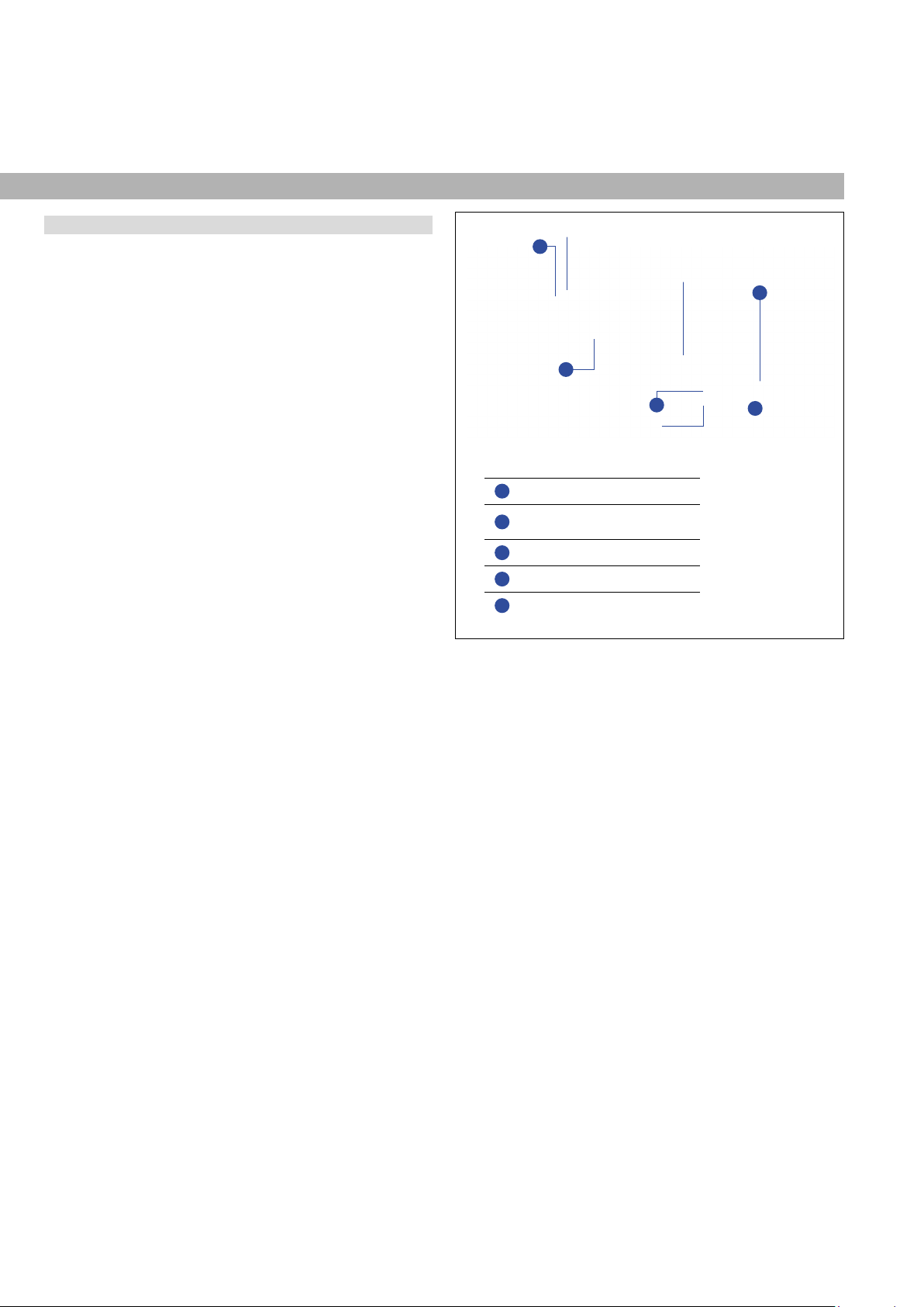
Fig. 2: Time-based magnetostrictive position sensing principle
Modular mechanical and electronic construction
• The sensor rod or prole protects the inner sensor element.
• The sensor electronics housing, a rugged aluminum construction,
contains the complete electronic interface with active signal
conditioning.
• The external position magnet is a permanent magnet. Mounted on
the mobile machine part, it travels along the sensor rod or prole
and triggers the measurement through the sensor rod wall.
• The sensor can be connected directly to a control system.
Its electronics generates a strictly position-proportional signal
output between start and end position.
5
3
1
Measurement cycle
1Current pulse generates magnetic eld
2Interaction with position magnet eld
generates torsional strain pulse
3Torsional strain pulse propagates
4Strain pulse detected by converter
5Time-of- ight converted into position
Sensing element (waveguide)
Position magnet (magnetic eld)
Torsional strain pulse converter
2
4

Temposonics® R-Series VPROFINET IO RT & IRT
Operation Manual
I 11 I
4.2 Installation and design of Temposonics®RP5
Fig. 3: Temposonics®RP5 with U-magnet/magnet slider
Controlling design dimensions are in millimeters and measurements in ( ) are in inches
Installation of RP5
The position sensor can be installed in any position. Normally,
the sensor is rmly installed and the position magnet is fastened
to the mobile machine part. Thus it can travel along the sensor prole.
The sensor is tted on a at machine surface using the mounting
clamps (Fig. 4). A length-dependent number of these clamps are
delivered with the sensor and must be distributed over the prole
at regular distances. For fastening use M5×20 screws to DIN 6912
that should be tightened with a fastening torque of 5 Nm.
Fig. 4: Mounting clamps (part no. 400 802) with cylinder screw M5×20
Fig. 5: T-slot nut M5 (part no. 401 602)
NOTICE
Take care to mount the sensor in an axially parallel position to
avoid damage to magnet and sensor.
Alternative:
If only limited space is available, the prole sensor can be mounted
also via the T-rail in the prole bottom using a T-slot nut M5
(part no. 401 602) or a sliding block (Fig. 5).
≤ 5
(≤ 0.2)
M5
Fastening torque: 5 Nm
50
(1.97)
9.5
(0.37)
Bore Ø 5.3
(Ø 0.21)
14.6
(0.57)
RP5-M, example: Connection type D58 (connector outlet)
Magnet
1
4 5
2
1
45
2
Port 1 L/A
MS/ER
NS/RN
L/A Port 2
45 (1.77)
9.5 (0.37)
48 (1.89)
50 (1.97)
68 (2.68)
Sensor electronics
housing
58
(2.28)
17
(0.67)
Dead zone
66/71*
(2.6/2.8*)
2 (0.08)
Ø 5.3
(
Ø 0.21)
35.6 (1.4)
* Stroke length > 5000 mm (196.9 in.)
28
(1.1)
14.6
(0.57)
Adjustable mounting clamp
e.g. for
M5 or
#10 screws
5
(0.2)
Stroke length
25…6350
(1…250)
Null zone
28
(1.1)
RP5-G/-S, example: Connection type D56 (connector outlet)
Magnet
68 (2.68)
45 (1.77)
9.5 (0.37)
48 (1.89)
50 (1.97)
2 (0.08)
Ø 5.3
(
Ø 0.21)
35.6 (1.4)
e.g. for
M5 or
#10 screws
Sensor electronics
housing
58
(2.28)
17
(0.67)
* Stroke length > 5000 mm (196.9 in.)
28
(1.1)
14.6
(0.57)
Adjustable mounting clamp
5
(0.2)
Stroke length
25…6350
(1…250)
Dead zone
66/71*
(2.6/2.8*)
Null zone
28
(1.1)
12
(0.47)
Start position
Controlling design dimensions are in millimeters and measurements in ( ) are in inches

Temposonics® R-Series VPROFINET IO RT & IRT
Operation Manual
I 12 I
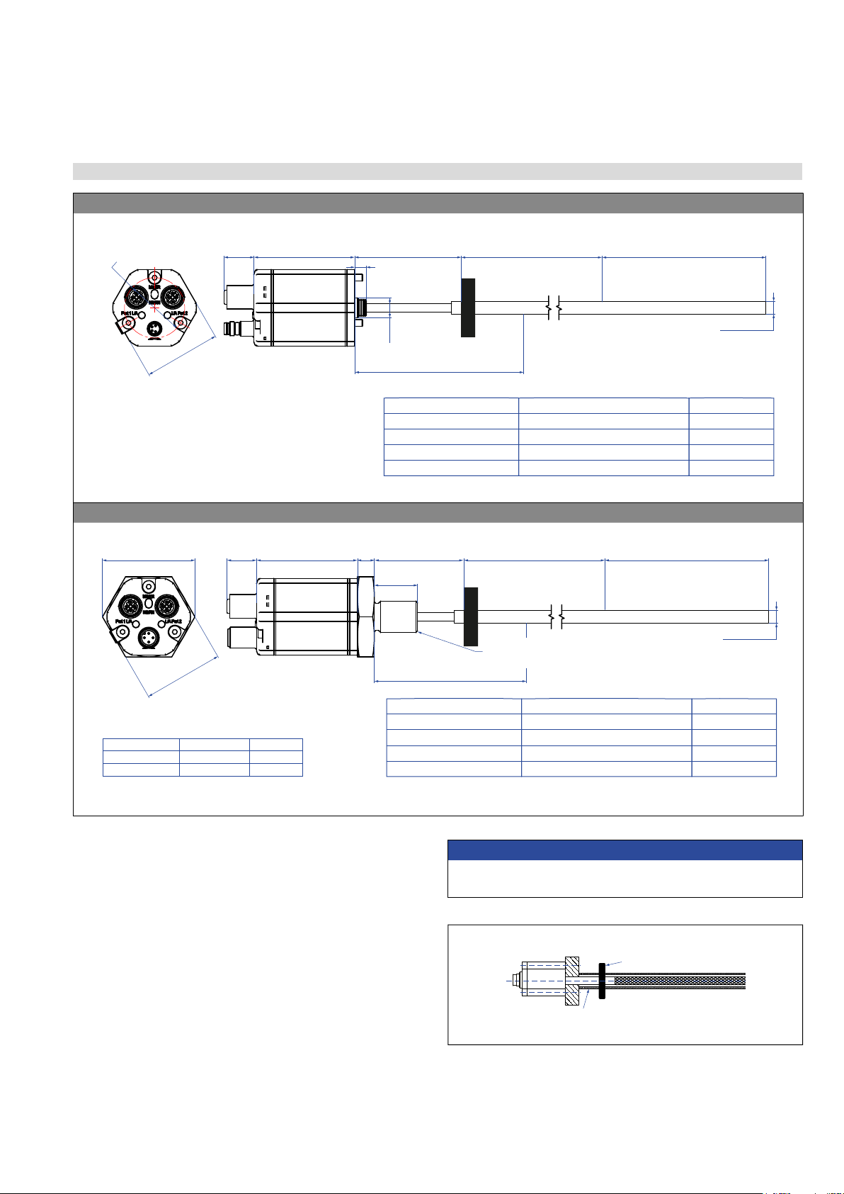
4.3 Installation and design of Temposonics®RH5
Fig. 6: Temposonics®RH5 with ring magnet, part 1
RH5-M/-S-A/-V – RH5 with threaded ange M18×1.5-6g or ¾"-16 UNF-3A, example: Connection type D58 (connector outlet)
MS/ER
NS/RN
1
4 5
2
1
4 5
2
a
17
(0.67)
Sensor electronics housing
68
(2.68)
Null zone
51
(2.01)
Threaded flange »M«: M18×1.5-6g
Threaded flange »S«: ¾"-16 UNF-3A
Magnet
Dead zone
63.5/66*
(2.5/2.6*)
Stroke length
25…7620
(1…300)
Ø 10 ±0.13
(Ø 0.39 ±0.01)
* Stroke length > 5000 mm (196.9 in.)
25
(0.98)
b
Threaded flange
»M«
»S«
a b
A/F 46 (1.81) 53 (2.09)
A/F 44.5 (1.75) 51.3 (2.02)
RH5-T-A/-V – RH5 with threaded ange ¾"-16 UNF-3A with raised-face, example: Connection type D56 (connector outlet)
17
(0.67)
Ø 25.4
(Ø 1)
Threaded flange »T«: ¾"-16 UNF-3A
Stroke length
25…7620
(1…300)
Sensor electronics housing
65.5
(2.58)
Null zone
51
(2.01)
Magnet
* Stroke length > 5000 mm (196.9 in.)
Dead zone
63.5/66*
(2.5/2.6*)
Ø 10 ±0.13
(Ø 0.39 ±0.01)
2.5
(0.1)
25
(0.98)
51.3
(2.02)
A/F 44.5
(A/F 1.75)
Mechanical option »B«: Bushing on rod end for threaded ange
M18×1.5-6g or ¾"-16 UNF-3A
Mechanical option »M«: Thread M4 at rod end for threaded ange
M18×1.5-6g or ¾"-16 UNF-3A
Dead zone
63.5/66*
(2.5/2.6*)
22
(0.87)
15
(0.59)
3
(0.12)
8
(0.31)
Ø 12.8 ±0.1
(Ø 0.5 ±0.004)
Ø 10
(Ø 0.39)
* Stroke length > 5000 mm (196.9 in.)
Dead zone
70/72.5*
(2.76/2.85*)
3.5
(0.14)
6
(0.24)
Thread M4
Ø 10 ±0.13
(Ø 0.39 ±0.01)
* Stroke length > 5000 mm (196.9 in.)
Controlling design dimensions are in millimeters and measurements in ( ) are in inches

Temposonics® R-Series VPROFINET IO RT & IRT
Operation Manual
I 13 I
Fig. 7: Temposonics®RH5 with ring magnet, part 2
RH5-J-A/-V – RH5 with threaded ange M22×1.5-6g and Ø 12.7 mm rod, example: Connection type D56 (connector outlet)
A/F 46
(A/F 1.81)
53
(2.09)
17
(0.67)
Sensor electronics housing
68
(2.68)
Null zone
51
(2.01)
Stroke length
25…5900
(1…232)
Threaded flange »J«: M22×1.5-6g
Magnet
Ø 12.7 ±0.13
(Ø 0.5 ±0.01)
Dead zone
73.6
(2.9)
25
(0.98)
RH5-B-A/-V – RH5 base unit (only for replacement), example: Connection type D58 (connector outlet)
MS/ER
NS/RN
1
4 5
2
1
4 5
2
48
(1.89)
17
(0.67)
Sensor electronics
housing
58
(2.28)
Null zone
61
(2.4)
Stroke length
25…7620
(1…300)
Dead zone
52/54/57**
(2.05/2.13/2.24)**
** Stroke length 25…1575 (1…62): 52 (2.05) dead zone
Stroke length 1576…5000 (62.05…196.9): 54 (2.13) dead zone
Stroke length 5001…7620 (196.9…300): 57 (2.24) dead zone
Controlling design dimensions are in millimeters and measurements in ( ) are in inches
Temposonics® R-Series VPROFINET IO RT & IRT
Operation Manual
I 14 I
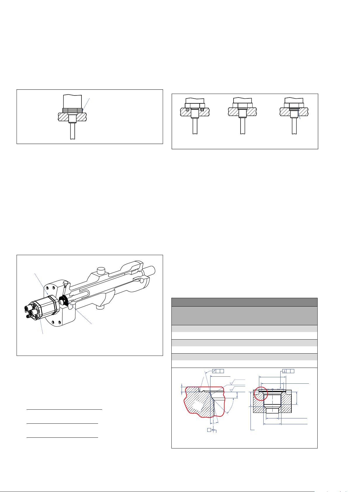
Hydraulics sealing
There are two ways to seal the ange contact surface (Fig. 10):
1. A sealing by using an O-ring (e.g. 22.4 × 2.65 mm (0.88 × 0.1 in.),
25.07 × 2.62 mm (0.99 × 0.1 in.)) in a cylinder end cap groove.
2. A sealing by using an O-ring in the ange undercut.
For threaded ange (¾"-16 UNF-3A):
O-ring 16.4 × 2.2 mm (0.65 × 0.09 in.) (part no. 560 315)
For threaded ange (M18×1.5-6g):
O-ring 15.3 × 2.2 mm (0.60 × 0.09 in.) (part no. 401 133)
For threaded ange (M22×1.5-6g):
O-ring 19.2 × 2.2 mm (0.76 × 0.09 in.) (part no. 561 337)
Installation of RH5 with threaded ange
Fix the sensor rod via threaded ange M18×1.5-6g, M22×1.5-6g or
¾"-16 UNF-3A.
Installation in a uid cylinder
The rod-style version has been developed for direct stroke
measurement in a uid cylinder. Mount the sensor via threaded ange
or a hex nut.
• Mounted on the face of the piston, the position magnet travels
over the rod without touching it and indicates the exact position
through the rod wall – independent of the hydraulic uid.
• The pressure resistant sensor rod is installed into a bore in the
piston rod.
• The base unit is mounted by means of three screws. It is the only
part that needs to be replaced if servicing is required, i.e. the
hydraulic circuit remains closed. For more information see chapter
“4.8 Replacement of sensor” on page 29.
Fig. 8: Mounting example of threaded ange
Fig. 9: Sensor in cylinder
In the case of threaded ange M18×1.5-6g or M22×1.5-6g, provide
a screw hole based on ISO 6149-1 (Fig. 11). See ISO 6149-1 for further
information.
• Note the fastening torque:
RH5-M: 65 Nm
RH5-S: 50 Nm
RH5-T: 55 Nm
RH5-J: 125 Nm
• Seat the ange contact surface completely on the cylinder
mounting surface.
• The cylinder manufacturer determines the pressure-resistant
gasket (copper gasket, O-ring, etc.).
• The position magnet should not grind on the sensor rod.
• The piston rod drilling
(RH5-M/-S/-T-A/-M/-V with rod Ø 10 mm: ≥ Ø 13 mm (≥ Ø 0.51 in.);
RH5-M/-S/-T-B with rod Ø 10 mm: ≥ Ø 16 mm (≥ Ø 0.63 in.);
RH5-J-A/-V with rod Ø 12.7 mm: ≥ Ø 16 mm (≥ Ø 0.63 in.))
depends on the pressure and piston speed.
• Adhere to the information relating to operating pressure.
• Protect the sensor rod against wear.
Fig. 10: Possibilities of sealing for threaded ange with at face 1. + 2.a. (RH5-J/-M/-S)
and with raised-face 2.b. (RH5-T)
Fig. 11: Notice for metric threaded ange M18×1.5-6g/M22×1.5-6g based on
DIN ISO 6149-1
Notice for metric threaded anges
Thread
(d1×P)
d2d3d4d5
+0.1
0
L1
+0.4
0
L2L3L4Z°
±1°
RH5-M-A/-M/-V
M18×1.5-6g 55 ≥ 13 24.5 19.8 2.4 28.5 2 26 15°
RH5-M-B
M18×1.5-6g 55 ≥ 16 24.5 19.8 2.4 28.5 2 26 15°
RH5-J-A/-V
M22×1.5-6g 55 ≥ 16 27.5 23.8 2.4 28.5 2 26 15°
Ød
5
Ra 3.2
Ra 3.2
Pitch diameter
A
A
Thread
(d
1
× P)
Ød
3
(Reference)
A
Ød
2
Ød
4
(Gauging)
This dimension applies when
tap drill cannot pass through
entire boss.
≤ R0.4
R0.3
R0.1
Z°
4
5
°
±
5
°
L
3
L
1
L
2
L
4
A0.1 A0.2
Controlling design dimensions are in millimeters
Fastening torque:
RH5-M: 65 Nm
RH5-S: 50 Nm
RH5-T: 55 Nm
RH5-J: 125 Nm
Sealing via O-ring
in the flange undercut
Sealing via O-ring
in cylinder end cap groove
Raised-
face
Sealing via O-ring
in the flange undercut
1.) 2.a.) 2.b.)
In the event of servicing, the sensor rod
with flange remains in the cylinder
Position magnet
Base unit
The sensor electronics housing
with sensing element can be replaced
Temposonics® R-Series VPROFINET IO RT & IRT
Operation Manual
I 15 I
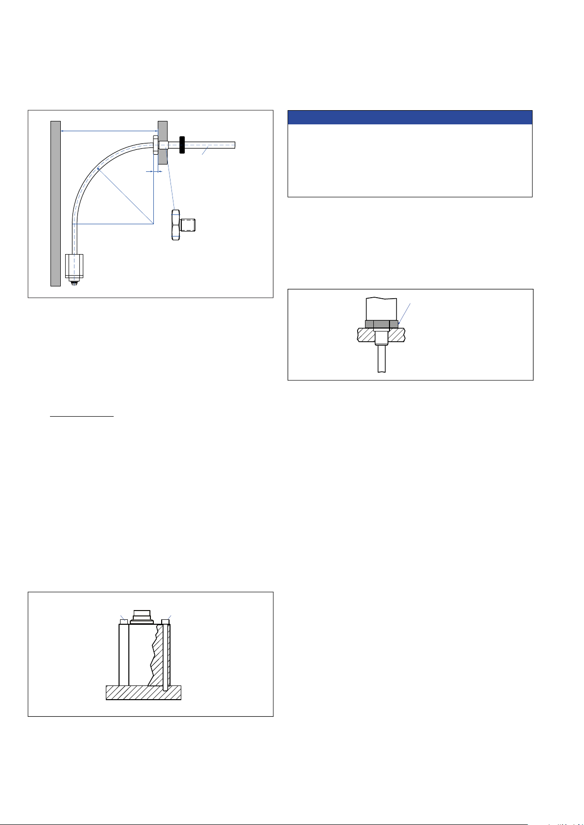
4.4 Installation and design of Temposonics®RFV
Fig. 12: Temposonics®RFV with ring magnet
Fig. 13: Sensor with support tube
Installation of RFV
Note the following information when mounting and handling an RFV
sensor:
1. Always insert the exible sensor rod in a support tube (e.g.
pressure rod HD/HL/HP or HFP prole). The support tube has
to be made of non-magnetic material and has to have an inside
diameter of minimum 9.4 mm (0.37 in.) (Fig. 13). The support
tube can be straight or bent.
2. Do never bend beyond the minimum bending radius of 250 mm
(9.84 in.).
3. Note the minimum distance to a spatial limitation of 300 mm
(11.81 in.), when mounting/dismounting the sensor. The
recommended distance is 500 mm (20 in.) (Fig. 14).
4. Note the non-exible area of the sensor rod from the ange of
107 mm (4.21 in.) (for RFV-B) respectively 97 mm (3.82 in.) (for
RFV-M/-S).
NOTICE
Smaller radiuses < 250 mm (9.84 in.) cause damage to the exible
sensor rod.
Position magnet
Non-magnetic support tube, inside Ø 9.4 (0.37)
Linear measurement
RFV-B – RFV base unit, example: Connection type D56 (connector outlet)
Magnet
Null zone
61
(2.4)
Dead zone
see table17
(0.67) 7
(0.28)
11.4
(0.45)
Not flexible
107 (4.2)
Stroke length
150…20,000
(6…787)
Ø 8 ±0.23
(Ø 0.31±0.01)
Sensor electronics housing
58
(2.28)
Tolerance of total length Dead zoneStroke length
Up to 7620 mm (300.00 in.)
Up to 10,000 mm (393.70 in.)
Up to 15,000 mm (590.55 in.)
Up to 20,000 mm (787.00 in.)
+8 mm (0.31 in.)/−5 mm (0.20 in.)
+15 mm (0.59 in.)/−15 mm (0.59 in.)
+15 mm (0.59 in.)/−30 mm (1.18 in.)
+15 mm (0.59 in.)/−45 mm (1.77 in.)
94 mm (3.70 in.)
100 mm (3.94 in.)
120 mm (4.72 in.)
140 mm (5.51 in.)
Note: Tolerance of total length has no influence on the stroke length.
44
(1.7)
Ø
34.6
(Ø 1.36)
RFV-M/-S – RFV with threaded ange M18×1.5-6g or ¾"-16 UNF-3A, example: Connection type D58 (connector outlet)
Magnet
Null zone
51
(2)
Dead zone
see table
1017
(0.67)
b
Not flexible
97 (3.82)
Stroke length
150…20,000
(6…787)
Ø 8 ±0.23
(Ø 0.31 ±0.01)
Threaded flange »M«: M18×1.5-6g
Threaded flange »S«: ¾"-16 UNF-3A
Sensor electronics housing
58
(2.28)
Tolerance of total length Dead zoneStroke length
Up to 7620 mm (300.00 in.)
Up to 10,000 mm (393.70 in.)
Up to 15,000 mm (590.55 in.)
Up to 20,000 mm (787.00 in.)
+8 mm (0.31 in.)/−5 mm (0.20 in.)
+15 mm (0.59 in.)/−15 mm (0.59 in.)
+15 mm (0.59 in.)/−30 mm (1.18 in.)
+15 mm (0.59 in.)/−45 mm (1.77 in.)
94 mm (3.70 in.)
100 mm (3.94 in.)
120 mm (4.72 in.)
140 mm (5.51 in.)
Note: Tolerance of total length has no influence on the stroke length.
a
Threaded flange
»M«
»S«
a b
A/F 46 (1.81) 53 (2.09)
A/F 44.5 (1.75) 51.3 (2.02)
Controlling design dimensions are in millimeters and measurements in ( ) are in inches
Controlling design dimensions are in millimeters and measurements in ( ) are in inches
Temposonics® R-Series VPROFINET IO RT & IRT
Operation Manual
I 16 I
Fig. 15: Mounting with socket head screws M4×59
Fig. 14: Clearances for installation and handling
Fig. 16: Mounting example of threaded ange
Mounting the RFV
1.RFV-B
• Insert the exible sensor rod in a support tube.
• Mount the sensor electronics housing by means of 3 non-
magnetic socket head screws M4×59. Fastening torque: 1.4 Nm
(Fig. 15). Secure the screws, e.g. using Loctite 243, before re-
installing.
Recommendation: Seal the sensor via ange.
2.RFV-B with pressure rod HD/HL/HP or HFP prole (see
“Frequently ordered accessories”)
• Advantage: The exible sensor rod is inserted in a support tube.
• Mount the sensor electronics housing by means of 3 non-
magnetic socket head screws M4×59. Fastening torque: 1.4 Nm
(Fig. 15). Secure the screws, e.g. using Loctite 243, before re-
installing.
• Installation details: see below
3.RFV-M/-S
• Insert the exible sensor rod in a support tube.
• Mount the sensor via ange.
• Installation details: see below
Installation of RFV with threaded ange »M« or »S«
Fix the sensor rod via threaded ange M18×1.5-6g or ¾"-16 UNF-3A.
Note the fastening torque of
RFV-M: 65 Nm
RFV-S: 50 Nm
Installation of RFV sensor with pressure rod HD/HL/HP in a uid
cylinder
The rod-style version has been developed for direct stroke
measurement in a uid cylinder. Mount the sensor via threaded ange
or a hex nut.
• Mounted on the face of the piston, the position magnet travels over
the rod without touching it and indicates the exact position through
the rod wall – independent of the hydraulic uid.
• The pressure resistant sensor rod is installed into a bore in the
piston rod.
• The base unit is mounted by means of only 3 screws. It is the
only part that needs to be replaced if servicing is required, i.e. the
hydraulic circuit remains closed. For more information see chapter
chapter “4.8 Replacement of sensor” on page 29.
• Note the fastening torque of
HD: 65 Nm
HL: 50 Nm
HP: 55 Nm
• Seat the ange contact surface completely on the cylinder mounting
surface.
• The cylinder manufacturer determines the pressure-resistant gasket
(copper gasket, O-ring, etc.).
• The position magnet should not grind on the sensor rod.
• The piston rod drilling for RFV sensors with pressure rod (outer
diameter 12.7 mm (0.5 in.)) is ≥ 16 mm (≥ 0.63 in.). The borehole
depends on the pressure and piston speed.
• Adhere to the information relating to operating pressure.
• Protect the sensor rod against wear.
500 (20) recommended
≥ 300 (≥ 11.81) Position magnet
10
(0.4)
A/F 46
Flange M18×1.5-6g
¾"-16 UNF-3A
Customized support tube
required e.g. Ø 12.7 × 1.65
(Ø 0.5 × 0.65),
inside Ø 9.4 (Ø 0.37),
non-magnetic
R > 250
(R > 9.84)
Fastening torque:
RFV-M: 65 Nm
RFV-S: 50 Nm
HD: 65 Nm
HL: 50 Nm
HP: 55 Nm
Socket head screw
M4×59
Socket head screw
M4×59
Fastening torque of socket head screw M4×59: 1.4 Nm
NOTICE
To fulll the requirements of EMC standards for emission and
immunity the following points are necessary:
• The sensor electronics housing has to be connected to machine
ground (Fig. 47).
• Embed the exible sensor element in an appropriately shielded
environment, e.g. in a pressure rod HD/HL/HP.
Controlling design dimensions are in millimeters and measurements in ( ) are in inches
Temposonics® R-Series VPROFINET IO RT & IRT
Operation Manual
I 17 I
Sealing via O-ring
in the flange undercut
Sealing via O-ring
in cylinder end cap groove
Fig. 17: Possibilities of sealing
Fig. 18: Notice for metric threaded ange M18×1.5-6g based on DIN ISO 6149-1
For additional information about the accessories HFP prole and
pressure rod HD/HL/HP see the accessories catalog (document part
number: 551444).
Notice for metric threaded anges
Thread
(d1×P)
d2d3d4d5
+0.1
0
L1
+0.4
0
L2L3L4Z°
±1°
RFV-M / optional pressure rod HD
M18×1.5-6g 55 ≥ 16 24.5 19.8 2.4 28.5 2 26 15°
Ød
5
Ra 3.2
Ra 3.2
Pitch diameter
A
A
Thread
(d
1
× P)
Ød
3
(Reference)
A
Ød
2
Ød
4
(Gauging)
This dimension applies when
tap drill cannot pass through
entire boss.
≤ R0.4
R0.3
R0.1
Z°
4
5
°
±
5
°
L
3
L
1
L
2
L
4
A0.1 A0.2
Controlling design dimensions are in millimeters
Replacing an R-Series 2004 RF-C with an R-Series VRFV-B.
If you are replacing the R-Series 2004 RF-C base unit with the
R-Series VRFV-B base unit, note the following points:
• The R-Series 2004 RF-C base unit is attached to the system with
two screws. The R-Series VRFV-B base unit is mounted to the
machine with three screws.
• Therefore, we recommend using the adapter plate kit 255198.
The adapter plate is used to mount the base unit RFV-B with three
screws to the existing hole pattern with two screws.
• Fasten the adapter plate to the existing hole pattern using the
two M4×6 (A/F 2.5) hexagon socket screws with a tightening
torque of 1.4 Nm. Ensure that the O-ring is correctly seated be-
tween the system and the adapter plate. Secure the screws with
Loctite 243.
• Place the RFV-B base unit on the adapter plate.
• Attach the grounding lug to one screw of the base unit.
• Screw the RFV-B base unit to the adapter plate using the three
M4×59 hexagon socket screws (A/F 2.5) with a tightening
torque of 1.4 Nm. Ensure that the O-ring is correctly seated be-
tween the base sensor and the adapter plate. Secure the screws
with Loctite 243.
• The adapter plate has a thickness of 5 mm. Order the RFV-B base
unit with the addition H003 to compensate for the thickness of the
adapter plate: RFV-B-xxxxxx-…-H003
Hydraulics sealing when using an RFV sensor in a pressure rod HD/
HL/HP
There are two ways to seal the ange contact surface (Fig. 17):
1. A sealing by using an O-ring (e.g. 22.4 × 2.65 mm (0.88 ×
0.1in.), 25.07 × 2.62 mm (0.99 × 0.1 in.)) in a cylinder end cap
groove.
2. A sealing by using an O-ring in the ange undercut.
For threaded ange (¾"-16 UNF-3A) »S«: O-ring 16.4 × 2.2 mm
(0.65 × 0.09 in.) (part no. 560 315)
For threaded ange (M18×1.5-6g) »M«: O-ring 15.3 × 2.2 mm
(0.60 × 0.09 in.) (part no. 401 133)
In the case of threaded ange M18×1.5-6g provide a screw hole based
on ISO 6149-1 (Fig. 18). See ISO 6149-1 for further information.
Temposonics® R-Series VPROFINET IO RT & IRT
Operation Manual
I 18 I
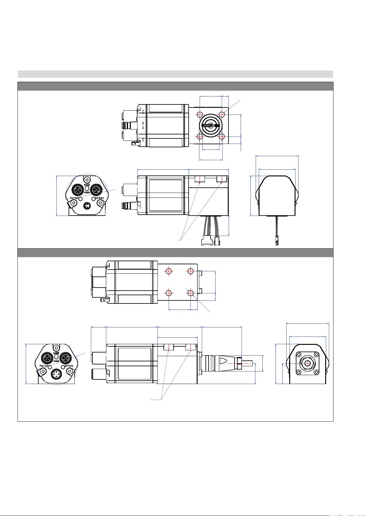
4.5 Installation and design of Temposonics®RDV
RDV with bottom cable entry, example: Connector D56 (connector outlet)
Recommendation:
Use M6×45 (ISO 4762) screws
Fastening torque: 6 Nm
50
(1.97)
58
(2.28)
45
(1.77)
45
(1.77)
8.2
(0.32)
24.7
(0.97)
7.7
(0.3)
24.7
(0.97)
Ø 19
(Ø 0.75)
Ø 26.2
(Ø 1.03)
Ø 48
(
Ø
1.89)
Ø 6.2
(Ø 0.24)
41
(1.61)
48
(1.89)
45
(1.77)
RDV with side cable entry, example: Connector D58 (connector outlet)
Recommendation:
Use M6×45 (ISO 4762) screws
Fastening torque: 6 Nm
17
(0.67)
Ø 48
(
Ø
1.89)
58
(2.28)
50
(1.97)
45
(1.77)
24.7
(0.97)
7.7
(0.3)
45
(1.77)
45
(1.77)
41
(1.61)
48
(1.89)
45
(1.77)
23
(0.9)
23
(0.9) Ø 18
(Ø 0.71)
8.2
(0.32)
24.7
(0.97)
Ø 6.2
(Ø 0.24)
Controlling design dimensions are in millimeters and measurements in ( ) are in inches
Fig. 19: Temposonics®RDV sensor electronics housing

Temposonics® R-Series VPROFINET IO RT & IRT
Operation Manual
I 19 I
Threaded ange »C« & »D« (for bottom or side cable entry)
Ø 10 ± 0.13
(Ø 0.39 ± 0.01)
4.5
(0.18)
PUR cable:
Ø 6 (Ø 0.24)
Bending radius:
> 24 (> 0.94)
Cable length (bottom cable entry):
65/170/230/350
(2.6/6.7/9.1/13.8)
Cable length
(side cable entry):
250/400/600
(9.8/15.7/23.6)
26.9
(1.1)
Null zone
51
(2.01)
32
(1.26)
Stroke length
25…5080
(1…200)
Dead zone
63.5/66*
(2.5/2.6)
Threaded flange »C«: M18×1.5-6g
Threaded flange »D«: ¾"-16 UNF-3A
* Stroke length > 5000 mm (196.9 in.)
Magnet
Cable for
bottom cable entry
Cable for
side cable entry
A/F 46
Threaded ange »M« (for bottom or side cable entry)
Ø 10 ± 0.13
(Ø 0.39 ± 0.01)
32
(1.26)
Null zone
51
(2.01)
Stroke length
25…5080
(1…200)
Dead zone
63.5/66*
(2.5/2.6*)
25
(0.98)
26.9
(1.1)
* Stroke length > 5000 mm (196.9 in.)
PUR cable:
Ø 6 (Ø 0.24)
Bending radius:
> 24 (> 0.94)
Cable length (bottom cable entry):
65/170/230/350
(2.6/6.7/9.1/13.8)
Cable length
(side cable entry):
250/400/600
(9.8/15.7/23.6)
Threaded flange »M«: M18×1.5-6g
Magnet
4.5
(0.18)
Cable for
bottom cable entry
Cable for
side cable entry
A/F 24
Threaded ange »T« (for bottom or side cable entry)
Threaded flange »T«: ¾"-16 UNF-3A
Ø 10 ± 0.13
(Ø 0.39 ± 0.01)
25
(0.98)
4.5
(0.18)
PUR cable:
Ø 6 (Ø 0.24)
Bending radius:
> 24 (> 0.94)
Cable length (bottom cable entry):
65/170/230/350
(2.6/6.7/9.1/13.8)
Cable length
(side cable entry):
250/400/600
(9.8/15.7/23.6)
Null zone
51
(2.01)
32
(1.26)
26.9
(1.1)
Stroke length
25…5080
(1…200)
Dead zone
63.5/66*
(2.5/2.6)
* Stroke length > 5000 mm (196.9 in.)
Magnet
Cable for
bottom cable entry
Cable for
side cable entry
A/F 23
Pressure t ange »S« (for bottom or side cable entry)
Ø 10 ± 0.13
(Ø 0.39 ± 0.01)
Null zone
21.4
(0.84)
32
(1.26)
12.7
(0.5)
4.5
(0.18)
Stroke length
25…2540
(1…100)
PUR cable:
Ø 6 (Ø 0.24)
Bending radius:
> 24 (> 0.94)
Cable length (bottom cable entry):
65/170/230/350
(2.6/6.7/9.1/13.8)
Cable length
(side cable entry):
250/400/600
(9.8/15.7/23.6)
Dead zone
63.5
(2.5)
26.9 f6
(1.1)
Magnet
Cable for
bottom cable entry
Cable for
side cable entry
Controlling design dimensions are in millimeters and measurements in ( ) are in inches
Fig. 20: Temposonics® RDV anges
Temposonics® R-Series VPROFINET IO RT & IRT
Operation Manual
I 20 I
Controlling design dimensions are in millimeters and measurements in ( ) are in inches
4.5.1 Installation of RDV with threaded ange
Fix the sensor rod via threaded ange M18×1.5-6g or ¾"-16 UNF-3A.
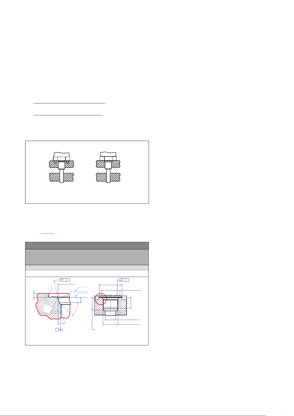
Hydraulics sealing
There are two ways to seal the ange contact surface (Fig. 22):
1. Sealing via an O-ring (e.g. 22.4 × 2.65 mm, 25.07 × 2.62 mm) in a
cylinder end cap groove (for threaded ange »C« / »D«)
2. Sealing via an O-ring 16.4 × 2.2 mm (part no. 560 315) in the
ange undercut.
For threaded ange (¾"-16 UNF-3A) »D« / »T«:
O-ring 16.4 × 2.2 mm (0.65 × 0.09 in.) (part no. 560 315)
For threaded ange (M18×1.5-6g) »C« / »M«:
O-ring 15.3 × 2.2 mm (0.60 × 0.09 in.) (part no. 401 133)
In the case of threaded ange M18×1.5-6g provide a screw hole based
on ISO 6149-1 (Fig. 23). See ISO 6149-1 for further information.
• Note the fastening torques:
RDV-T: 65 Nm
RDV-M: 55 Nm
RDV-C: 65 Nm
RDV-D: 75 Nm
• Seat the ange contact surface completely on the cylinder mounting
surface.
• The cylinder manufacturer determines the pressure-resistant gasket
(copper gasket, O-ring, etc.).
• The position magnet should not grind on the sensor rod.
• The piston rod drilling (≥ Ø 13 mm (≥ Ø 0.51 in.)) depends on the
pressure and piston speed.
• Adhere to the information relating to operating pressure.
• Protect the sensor rod against wear.
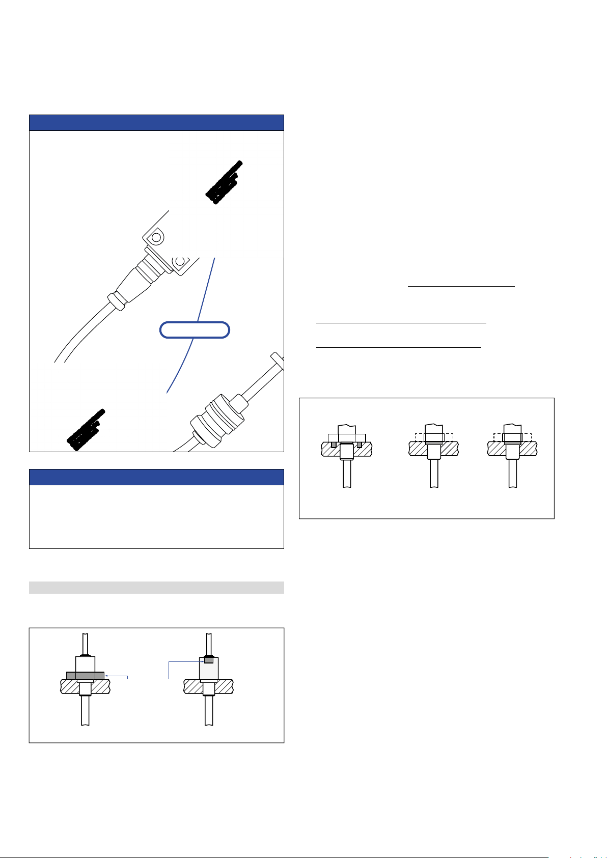
Fig. 21: Mounting example of threaded ange »C« / »D«, »M« / »T«
Fig. 22: Possibilities of sealing
NOTICE
S/N: 70019012
14133950141339501413395014133950
S/N: 70019012
14133950141339501413395014133950
S/N: 70019012
Note for installation respectively
for replacement of RDV
The serial numbers (S/N) of cable
and sensor electronics housing must
match, so that the position
measurement is correct.
Serial number
example
NOTICE
Mount the sensor as follows:
1. Mount the ange with sensor rod
2. Mount the sensor electronics housing
3. Connect the cable between ange and the sensor electronics
housing
The steps mentioned above will be explained in the following sections.
Installation of a rod-style sensor in a uid cylinder
The rod-style version has been developed for direct stroke
measurement in a uid cylinder. Mount the sensor via threaded ange
or a hex nut.
• Mounted on the face of the piston, the position magnet travels
over the rod without touching it and indicates the exact position
through the rod wall – independent of the hydraulic uid.
• The pressure resistant sensor rod is installed into a bore in the
piston rod.
Threaded flange »M« / »T«Threaded flange »C« / »D«
Fastening torques:
RDV-T: 65 Nm
RDV-M: 55 Nm
RDV-C: 65 Nm
RDV-D: 75 Nm
Sealing via O-ring
in cylinder end cap groove
For threaded flange
»C« / »D«
Sealing via O-ring
in the flange undercut
For threaded flange
»D« / »T«
Sealing via O-ring
in the flange undercut
For threaded flange
»C« / »M«
This manual suits for next models
4
Table of contents
Other Temposonics Accessories manuals


