Temspec VGB Series Manual

Operation & Maintenance Manual
VGB & HGB Series
Classroom Fan Coil Units
Form VGB-OM-MANUAL-Rev02
IMPORTANT: Read and save this manual for future reference.
This manual is to be left with the equipment owner
Operations & Maint.Manual VGB HGB SeriesRev3.doc
[1]
Table of Contents
INTRODUCTION
About the Classroom Fan Coil unit .………………………………………………………2
Nomenclature for Classroom Fan Coil units ………………………….……………………2
TYPICAL UNIT LAYOUT
Model VGB 1600 DDX / DCW ……………………………………….………………………3
Model VGB 1600 BCW / BDX ……………………………………….………………………4
Model HGB 1600 ……………………………………………………….………………………5
OPERATION
Control Strategy with Chilled Water Cooling, Electric or Hot Water Heating …………..……6
Control Strategy with DX Cooling, Electric or Hot Water Heating …………………..……7
Chilled Water Circuit .……………………………………………………………………….8
Refrigeration Circuit………....……………………………………………………………….…….9
Electrical Circuit ……….….………………………………………………………………..…10
Damper ……….………….………………………………………………………………..…10
Filtration ……….………….………………………………………………………………..…10
MAINTENANCE
Servicing the Unit ………….………….………………………………………………………..11
Maintenance Schedule ….………….……………………………………………………..…11
Changing the Filters………….………….……………………………………………………..…12
Cleaning the Evaporator Coils …….………………………………………………………...12
Motors ………………………….…………………………………………………………...12
TROUBLESHOOTING
Basic Troubleshooting Guidelines…..…………………………………………………………..13
REPLACEMENT PARTS
Limited Warranty ..……………………...………………………………………………………14
Part Sales …………..………………………..…….…………………………………………....14
INTRODUCTION

Operations & Maint.Manual VGB HGB SeriesRev3.doc
[2]
The Temspec VGB/HGB classroom fan coil unit is designed as means for providing
cooling, heating and ventilation to the classroom. Our goal is to help create an enhanced
learning environment by focusing on the following points when designing our equipment:
•COOLING, HEATING, HUMIDITY AND VENTILATION
CONTROL
•AIR DISTRIBUTION
•SOUND ATTENUATION
By installing the VGB/HGB fan coil unit into the classroom, superior control can be obtained
for each room. Because the unit can be ducted, an even distribution of air can be achieved
throughout the room. The classroom fan coil unit is constructed with heavy gauge metal
and sound absorbing insulation for optimal sound attenuation.
By applying sound engineering principles and thorough testing, we ensure the highest
quality of performance in our unit ventilators.
ABOUT THE CLASSROOM FAN COIL UNIT
NOMENCLATURE FOR CLASSROOM FAN COIL UNITS
V=Vertical Unit
H=Horizontal
GB = Dual coil type of classroom fan coil unit
1600 = up to 1600 cfm of supply air
1600
GB
V
B=Blow through SA fan configuration
D=Draw through SA fan configuration
B
CW = Chilled water cooling
DX = Split system DX cooling
CW
Operations & Maint.Manual VGB HGB SeriesRev3.doc
[3]
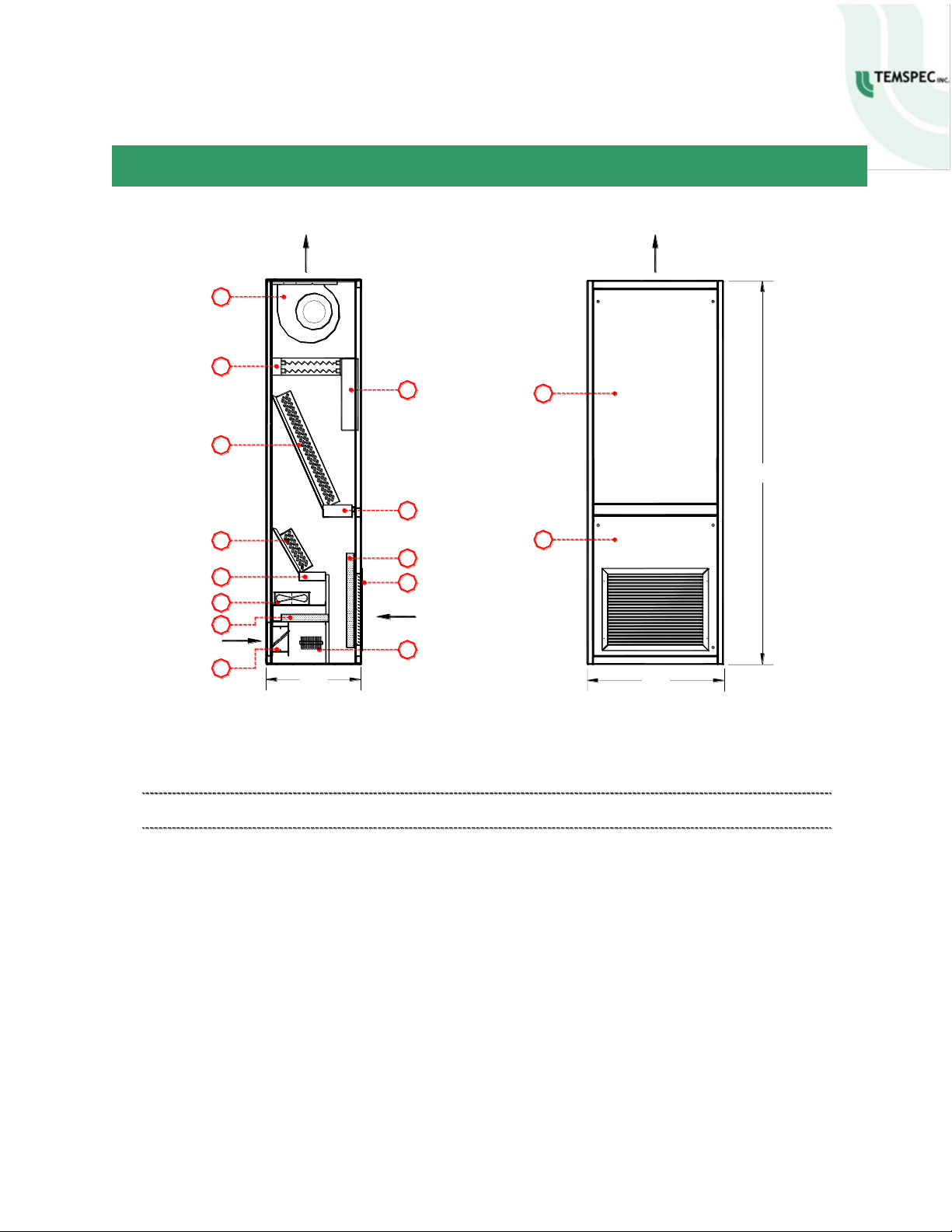
TYPICAL LAYOUT
O.A. Outdoor Air
11
10
1. Supply air fan.
2. Optional electric coil.
3. Control / electrical enclosure.
4. Primary coil (DX or chilled water).
5. Drain pan.
6. Outdoor air coil (DX or chilled water).
7. Return air filter.
O.A.
9
5
23"
S.A. Supply Air
SIDE SECTION
12
R.A.
8
7
6
4
1
2
S.A.
3
5
8. Heavy duty return air grille.
9. Outdoor air fan.
10. Outdoor air filter.
11. Outdoor air damper.
12. Optional electric freeze protection.
13. Coil access panel.
14. Return air access panel.
FRONT ELEVATION
R.A. Return Air
33"
14
13
S.A.
93"
NOTE: The component arrangement shown above may vary slightly from that in the unit supplied.
Model VGB 1600 DDX / DCW (Upflow, Ducted Configuration)
Operations & Maint.Manual VGB HGB SeriesRev3.doc
[4]
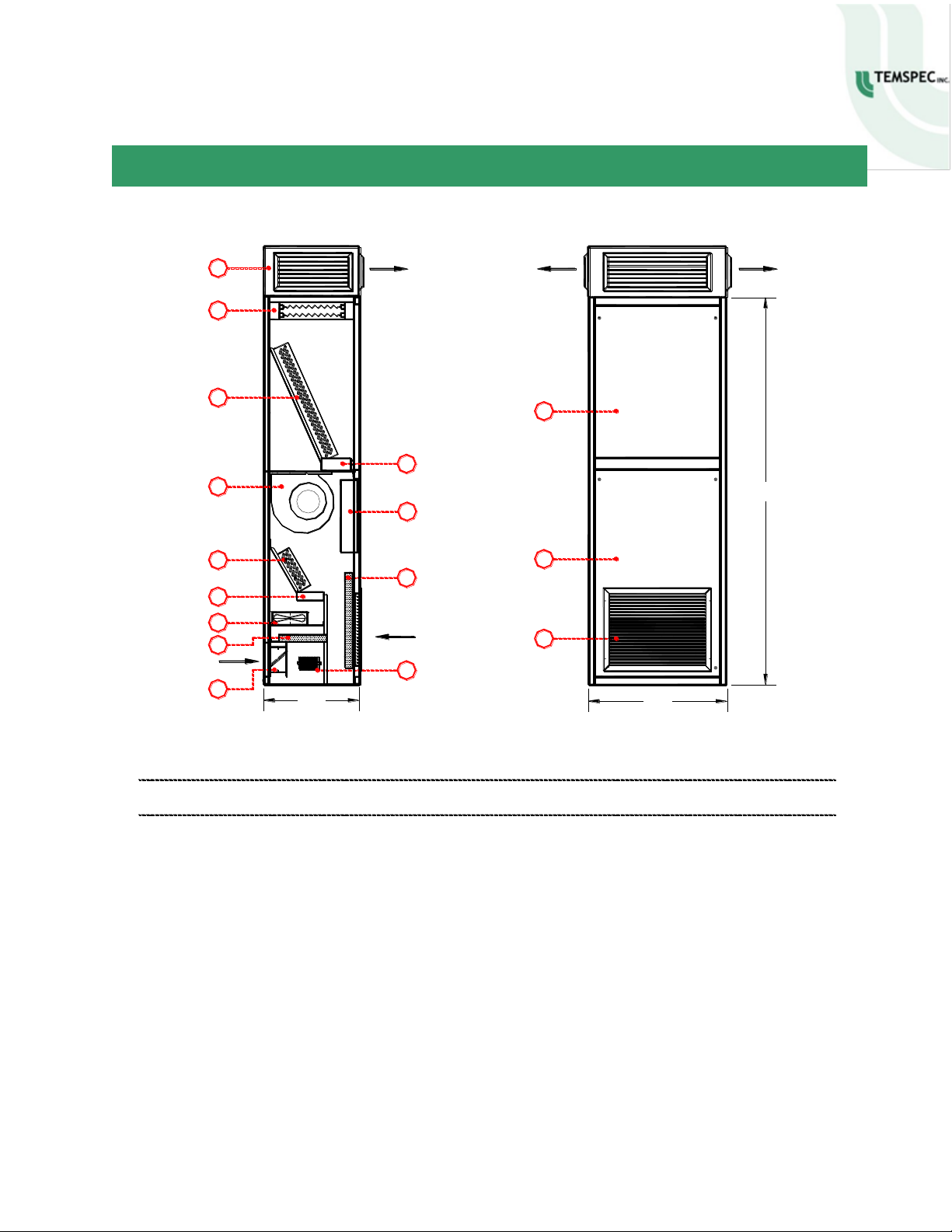
TYPICAL LAYOUT
O.A. Outdoor Air
1. Optional top plenum with double
deflection supply air grilles.
2. Optional electric coil.
3. Primary coil (DX or chilled water).
4. Drain pan.
5. Supply air fan.
6. Control / electrical enclosure.
7. Outdoor air coil (DX or chilled water).
11
10
9
O.A.
4
7
23"
SIDE SECTION
S.A. Supply Air
12
R.A.
8
5
3
2
6
4
S.A.
8. Return air grille.
9. Outdoor air fan.
10. Outdoor air filter.
11. Outdoor air damper.
12. Optional electric freeze protection.
13. Coil access panel.
14. Return air access panel.
15. Heavy duty return air grille.
FRONT ELEVATION
15
14
33"
R.A. Return Air
S.A.
13
S.A.
93"
1
NOTE: The component arrangement shown above may vary slightly from that in the unit supplied.
Model VGB 1600 BDX / BCW (Upflow, Freeblow Configuration)
This manual suits for next models
4
Table of contents


