Ten-Haaft Oyster Vision II User manual
1
Assembly Instructions
Oyster Vision II
Issue: Mai 2006

2
ASSEMBLY INSTRUCTIONS
Don’t worry – it does not require any witchcraft to assemble the mobile
satellite system Oyster Vision II. Some points should be observed,
however. Please accurately follow these assembly instructions so that
afterwards your unit will operate to your full satisfaction.
If necessary, mounting and operating instructions can also be
downloaded over the internet from www.ten-haaft.de.
Please completely read each point at least once before you begin to
execute it.
In this way, complete point for point successively.
Note:
This is a sensitive device. Do not tear at the dish arm. Do not
manually lift or turn the dish arm; the dish arm may only be
moved by the motor. Only raise at plastic screen or aluminium
plate. The screws at the plastic housing may be loosened only
by the manufacturer of the unit.
Caution:
Never grip into the range of the external unit while it is moving!
Note for operation on caravans/trailers:
The 12 V board system power supply which is generated by voltage
transformers built into caravans as a standard is frequently not stable
enough for the operation of the satellite system.
We recommend the auxiliary transducer which can be ordered from
us for installation into caravans.

3
Scope of delivery
The following items should now be in front of you:
Operating control device
Control unit
External unit
Dish
Mounting plate
Screw package
Cable set to the external unit (white coax cable together with
control cable in black sheath)
Coax cable for connection of your satellite receiver with the
control unit
Western cable (connection between control unit and
operating control device)
Power cable (control unit)
Operating instructions
Assembly instructions
In addition required for television reception:
Satellite receiver (not comprised in the scope of delivery)

4
Disposal note for packaging material
Packaging materials and packaging auxiliaries are recyclable
and must in principle be supplied to material recycling.
Packaging materials, e.g. plastic bags, should not be made
accessible to children.
Please also observe the notes regarding environmental
protection on page 20.
5
Assembly
1. Preparation
It is important that the roof of your vehicle is sufficiently stable.
In case of insufficient or doubtful roof stability, a piece of sheet
metal with a thickness of approx. 2 mm and a size of approx. 100 x
100 cm should be attached on the roof’s outer skin. Please consult
your vehicle manufacturer.
For the assembly of the unit you require a wrench of the sizes 13 mm and
27 mm each, a large Philips screwdriver, a drill with 25 mm in diameter or
milling cutters, a drill press, a sharp knife (carpet knife), slotted
screwdriver 3 mm, nipper pliers, industrial cleaner for cleaning the
assembly plate, and a strongly sticking body sealing compound (e.g.
Sikaflex).
2. Selecting the mounting position
After now all doubts are eliminated concerning roof stability and/or all
necessary measures have been taken for proper assembly, provisionally
put the external unit with assembly plate on the mounting position
planned for it.
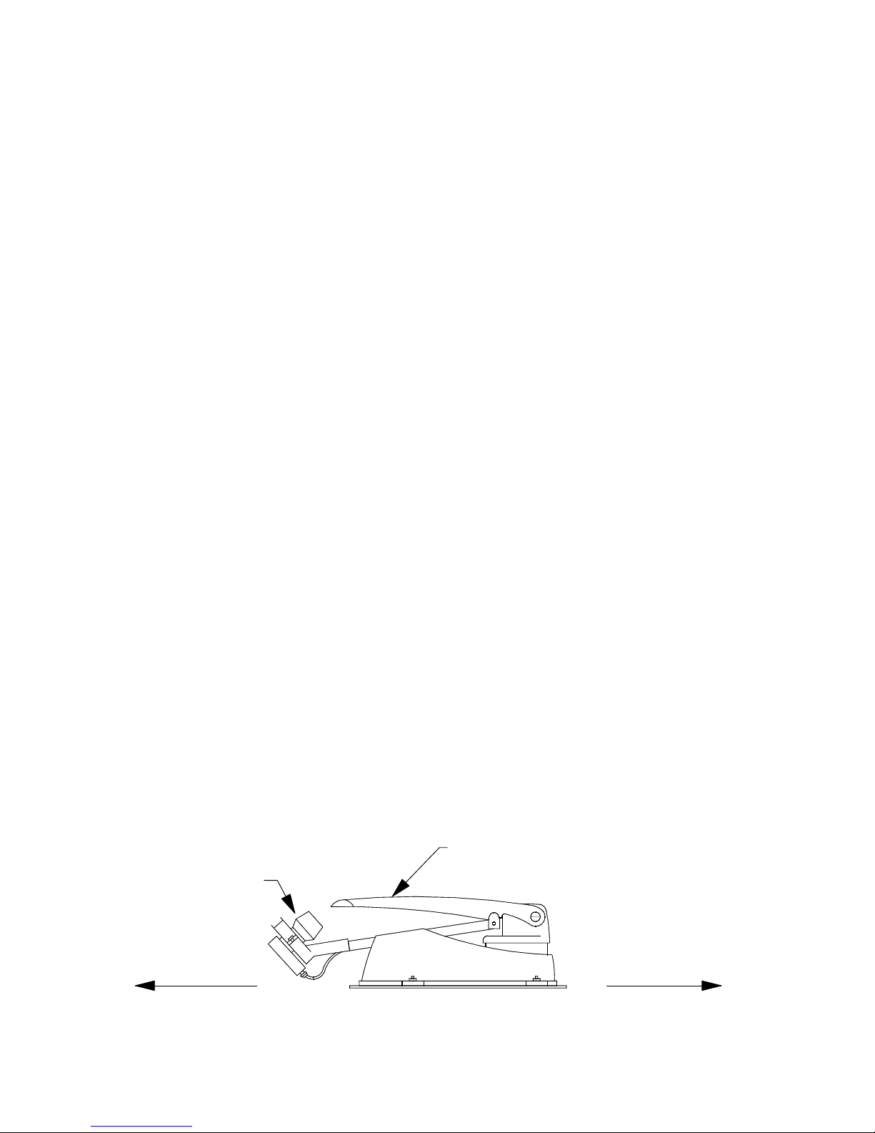
Correctly placed, the dish arm as well as the LNB must now be
positioned toward the rear of the vehicle; other positions are not correct –
see drawing below. With the CARO system, the LNB is integrated in the
antenna surface and therefore not visible. Mount the CARO with the
hinge pointing in the driving direction.
For the final choice of the mounting position, make absolutely sure
of the necessary space requirements and consider the choice of
location of the individual devices in order to later facilitate the
installing of cables.
LNB
Rear of vehicle
External unit with
dish arm
Driving direction
6
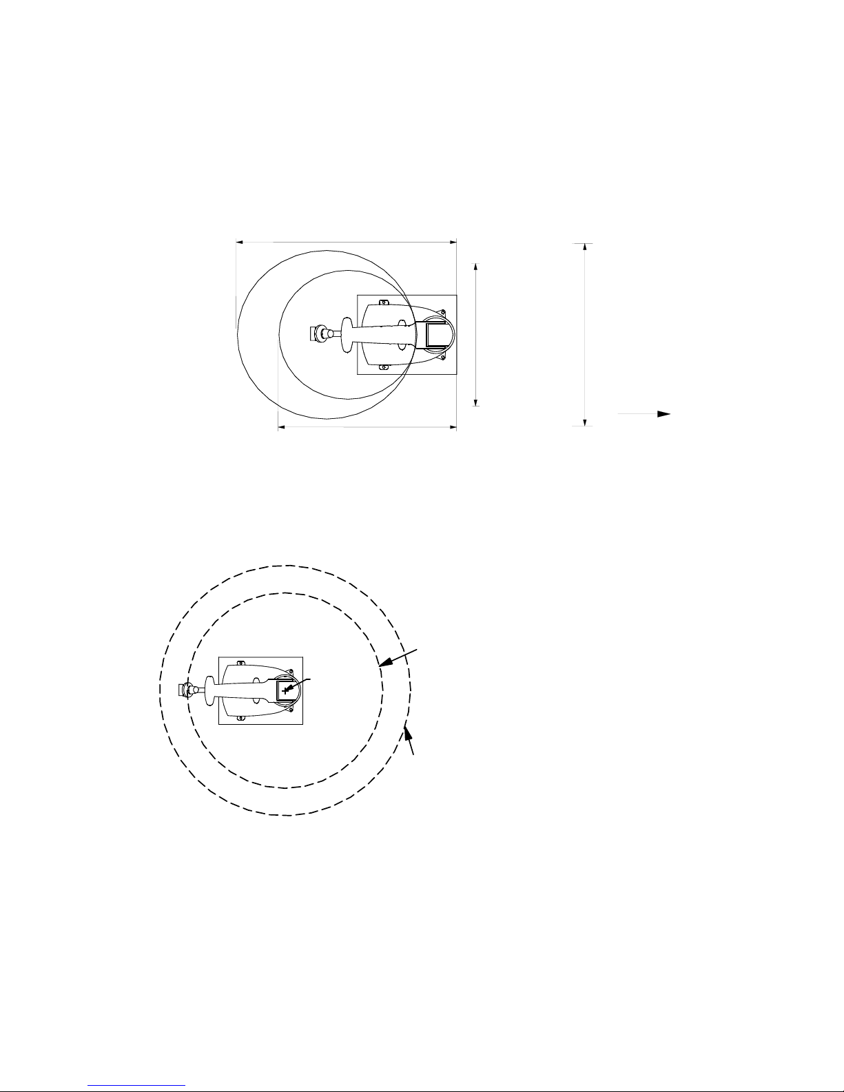
1. Space requirement of the external unit
Make sure that sufficient room is available for the folded-up system as
well as for the radius of action (turning radius).
Generally,the following space is required for the folded-up system:
Later on, the system must be mounted in such a way that the LNB points
to the rear of the vehicle (see drawing on previous page).
For the radius of action during the rotation of the antenna, likewise
sufficient space must be planned. That means that roof systems, e.g. air
conditioning systems, roof lights in opened state, roof suit-cases etc.,
must be located outside of the radius of action indicated above.
r
e
t
s
y
Owidth 72 cm
Oyster 65: Oyster 85:
width 92 cm
Driving direction
Oyster 85: length 111.5 cm
Oyster 65: length 91.5 cm
r
e
t
s
y
O
Radius Oyster 85:
Radius Oyster 65:
Centr 54 cm to 55 cm height
65 cm to 55 cm height
7
2. Mounting of the assembly plate
After the final mounting location for the unit has now been established
and you have again verified the correct position in relation to the driving
direction, mark the corner points of the assembly plate.
Attention!
Additionally, it is absolutely mandatory to mark with a line the assembly
plate and the vehicle roof in order to exclude a directionally wrong
assembly. The Oyster can be attached only in one position on the
assembly plate. Thereby the LNB must show toward the rear of the
vehicle. Every other position of the unit is incorrect and causes expiring of
the guarantee.
Now remove the system from the assembly plate by means of the four
assembly nuts.
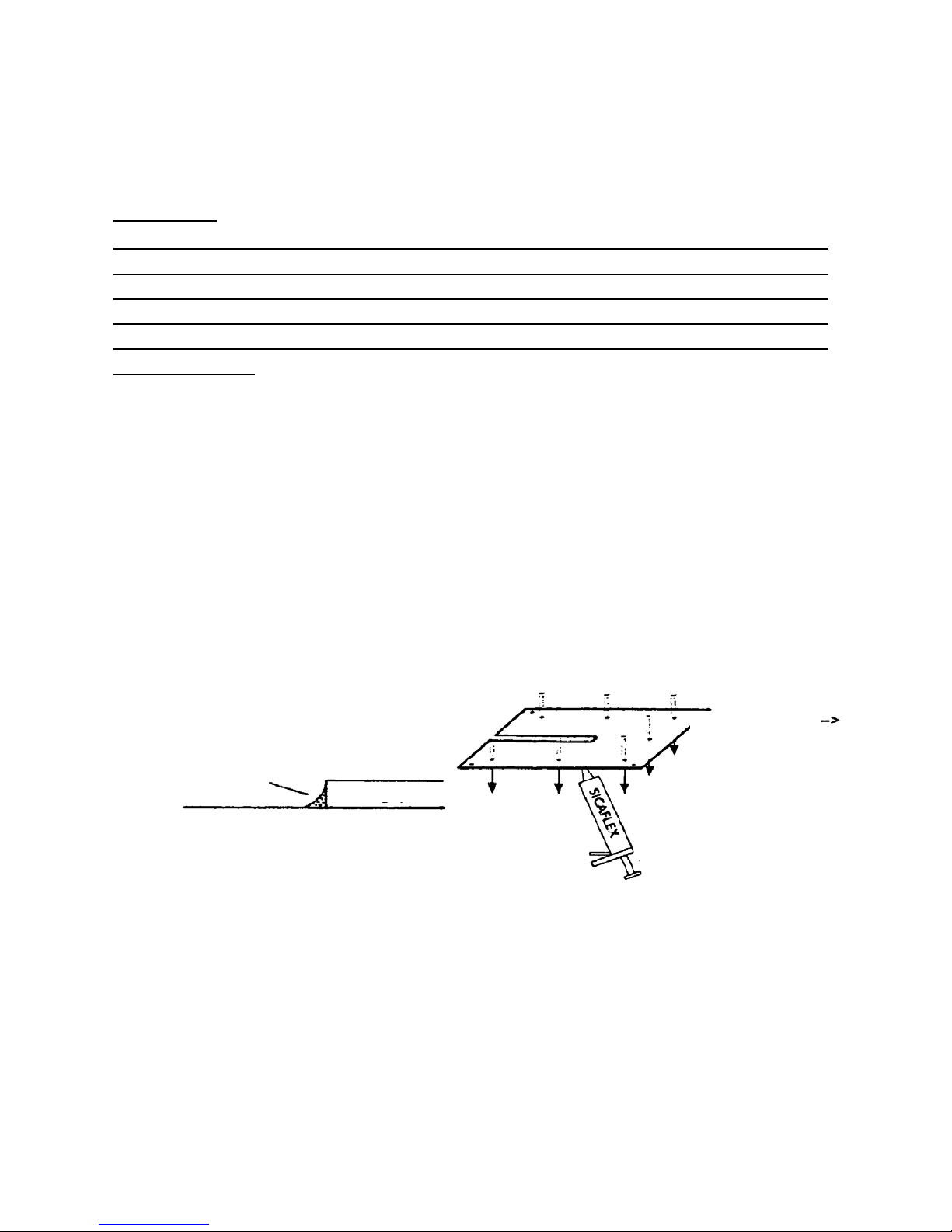
The assembly plate is to be glued to the vehicle roof with commercially
available body sealing compound, and afterwards bolted. For the
cleaning of assembly plate and roof, please use a special cleaning agent
which is recommended by the manufacturer of the body sealing
compound (e.g. Sikaflex, Teroson 1K-Pur). After ventilating of the
cleaner, apply the sealing compound to the bottom of the assembly plate,
and after setting it on the roof bolt it with the included tapping screws (see
drawing).
Also seal edges of
assembly plate
Sealin
g
com
p
ound
Assembly plate
Vehicle roof
Rear Driving direction

8
3. Elbow connector
The elbow connector on the roof must be aligned toward the rear of the
vehicle, thus the cable input will point to the rear and is splash-proof.
It is of advantage for an uncomplicated installing of cables inside the
vehicle to have the distance between elbow connector and receiver as
short as possible.
4. Mounting the system
First, connect the large cable set with the external unit. To do this, tilt the
external unit on the side. The plug connection takes place in the pit in the
bottom of the housing body. Now mount the external unit on the assembly
plate and insert the cable into the small recess of the base plate to the
rear. If earlier the assembly plate was mounted correctly, then the LNB
now points toward rear of the vehicle. Do not yet bolt the external unit to
the assembly plate.

9
5. Attaching the elbow connector (roof feed-through)
The elbow connector must be mounted on the vehicle roof in such a way
that it points toward the rear of the vehicle, and accordingly the cable
input will be located at the rear and is splash-proof.
a) Make a roof cut-out with approx. 25 mm diameter for the cable entry.
b) The small assembly plate for the elbow connector is glued to the
vehicle roof with commercially available body sealing compound and
afterwards bolted. For the cleaning of the small assembly plate and the
roof please, use a special cleaning agent which is recommended by the
manufacturer of the body sealing compound (e.g. Sikaflex, Teroson 1K-
Pur). After ventilating of the cleaner, apply the sealing compound to the
bottom of the assembly plate, and after setting it on the roof bolt it with
the included 4 tapping screws
c) Now apply strongly sticking body sealing compound to the bottom of
the elbow connector and mount it on the assembly position (small
aluminium plate). Thereby pay attention to correct seat of the O ring!
d) Afterwards, the elbow connector is screwed to the roof with the two
included tapping screws. However, do not yet fasten the nut of the elbow
connector!
e) Seal the lower edge of the elbow connector as well as the tapping
screws all-around likewise with sealing compound.
f) Now fasten the nut at the elbow connector with a 27 mm wrench in
clockwise direction.
Finally check the tightness at the cable entry, at the tapping screws,
and at the foot of the elbow connector.
O
Elbow connecto
r
Roof feed-through ø 25 mm

10
6. Installing the cables
a) Lead the cable coming from the elbow connector downwards to the
control unit.
b) For the cable distance between the external unit and the elbow
connector on the vehicle roof, you can use the commercially available
cable troughs.
c) Should the cable be too long within the vehicle, you can coil it up.

11
7. Power supply
Provide for a sufficient power supply of the system.
a) The system requires connection to 12 V or 24 V on-board power.
b) For the connection to the on-board power, the cable diameter must not
be below 2.5 mm2. For cable lengths of 6 m or more, use a cross section
of at least 4.0 mm2.
c) In most cases, a connection to the on-board power over existing lines
is not ideal. Often the cable diameter is too low and/or different users,
e.g. the television set, are already being supplied via these lines. The
available voltage is then usually not sufficient.
d) Recommended and at the same time the optimal solution is to install a
separate on-board power line for the unit to the battery. The fuse
protection of this line must be between 10 and 20 A.
Power supply in caravans / trailers
In caravans there is frequently no stable and/or battery backed-up 12 V
board power supply available. In this case it is necessary to supply the
system via a suitable voltage transformer 220 V/12 V from the mains
power net.
Do not use under any circumstances battery chargers, simple
transformers, or non-stabilized power packs. Suitable are exclusively
electronically controlled stabilized power packs with a nominal voltage of
13,8 V and a permanent current load capability of at least 6 A.
We strongly recommend the use of the auxiliary transducer which can be
obtained from us.
After the correct connection of the system to the battery has been
established, the system will perform a self-test.
Should you now see any error messages appearing on the display of the
control device, look up the cause on page 19.
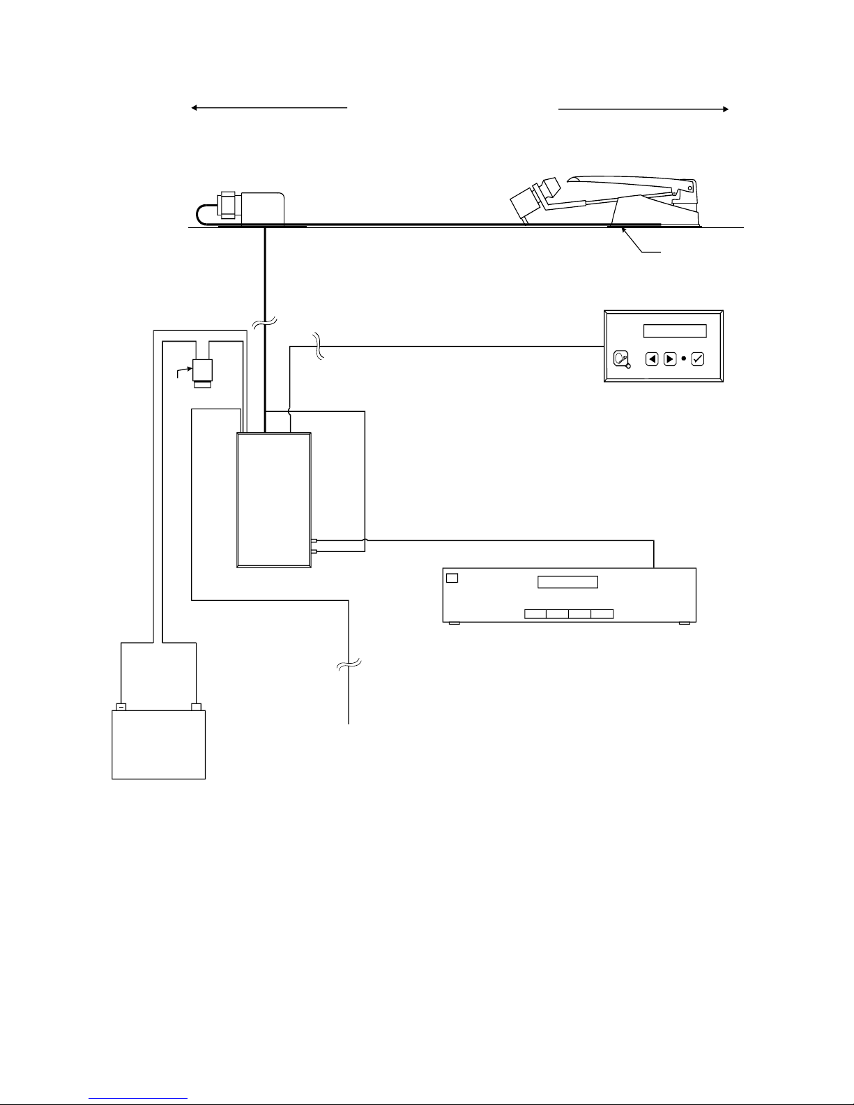
12
V
ision
+
S
i
c
h
e
r
u
n
g
s
h
a
l
t
e
r
On-board battery
Length 4.5 m from
external unit
Ignition
Pin 15 / D+
s
c
h
w
a
r
z
red
brow
Elbow connecto
r
External unit
Assembly plate
Control unit
Operating control device
Western cable length 6.5 m
from operating control device
Coax cable
Length 1.5 m from control unit
Receive(not comprised in scope of delivery)
Rear of the vehicle Driving direction

13
Connector identification at the control unit:
Receiver Connect this socket with the input socket of your
satellite receiver using the included shorter coax cable.
F-Plug
Connect here the antenna plug (BNC plug) of the
provided control cable to the external unit. (Control
cable and coax cable to the external unit are together in
a black sheath.)
Connect here the white 15 pin plug of the provided
control cable to the external unit. (Control cable and
coax cable to the external unit are together in a black
sheath.)
30/3 1/15
Connect here the provided power cable.
ATTENTION! Make sure beforehand that the power
cable is correctly connected to electricity mains of the
vehicle at the other end; in case of wrong polarity the
control unit can be destroyed!
Connect here the provided Western cable (similar to a
telephone line), and plug the other cable end into the
operating control device.
GPS
antenna
Without meaning
GPS
extern
Without meaning

14
8. Protection circuit
In order to prevent damage by inadvertently driving with a folded-up
external unit, the black line of the voltage supply of the receiver must be
connected to "pin 15" (pin 15 is a line which does lead voltage during
switched-on ignition and no voltage with switched-off ignition). The unit
will then automatically retract as soon as the ignition is switched on.
In addition, the unit cannot be extended with switched-on ignition.
Note:
Use for the connection only a switched plus wire, not the D-plus line of
the generator. With many vehicles, the D-plus line does not switch
through a clean DC voltage; in addition there are not immediately
available approx. 12 volts on this line but often a voltage is only slowly
built up. This can lead to functional problems with the processor in the
receiver.
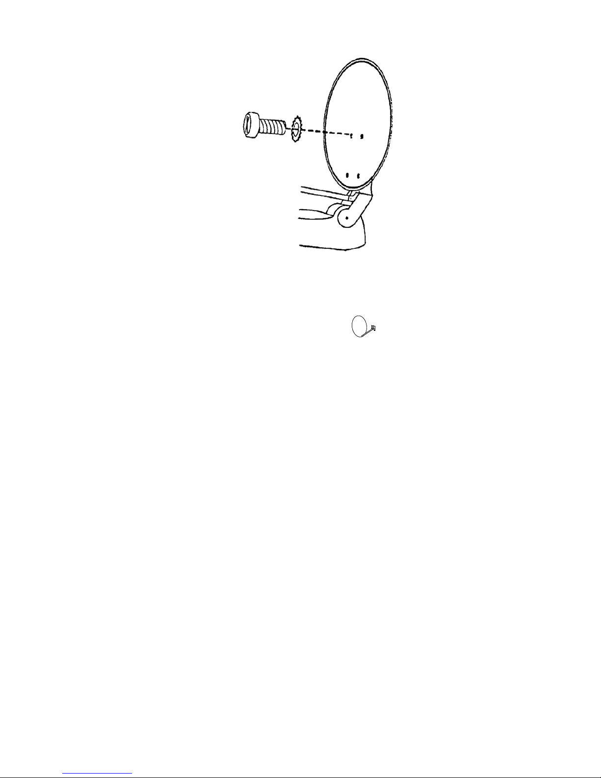
9. Mounting the dish antenna
After now all devices have been connected, next the dish antenna will be
mounted.
Attention: First make sure that within the range of the external rotating
unit no tools or the like prevent rotary motions of the system.
a) Switch on the control unit with the key. The external unit must now
extend.
b) When the external unit is in approximately vertical state, interrupt the
movements by pressing the key .
Absolutely wait until the system does not move any longer before you
start with the assembly of the dish.
Now the antenna dish should be bolted onto the dish arm with the four
Philips bolts and lock washers.
15
Retract the system again by pressing the key on the operating control
device.
10. Receiver connection
Now you can connect the system to your receiver (not comprised in the
scope of delivery) by screwing the F-plug at the white coax cable to the F-
socket of the satellite input.
Now you must fasten the cap nut at the cable entry on the roof.
Now bolt the external unit to the assembly plate by means of the 4
assembly nuts.

16
11. Adjusting TV set and receiver
There are two possibilities of interconnecting receiver and television set.
Follow the instructions of one of the two points only!
Either: Connection with a TV coax cable (generally available in stores,
not comprised in the scope of delivery); sound reproduction will be only in
mono.
First, the receiving channel of the satellite receiver must be stored at the
TV set. (Refer to the operating instructions of your TV set regarding the
procedures for channel selection and storage.) The system must be
switched on (see menu option 12) in order to transfer a menu or a
television picture to the TV set. Now the receiving channel can be
searched at the TV set (see TV operating instructions). If a picture (menu
text or TV programme) appears on the TV, the correct channel has been
found. You should now store this channel at a program place of your
choice.
Or: Connection via the TV Scart socket with a Scart cable (generally
available in stores, not comprised in the scope of delivery). Over this
connector a stereophonic sound play-back is possible.
You do not need to connect the provided TV coax cable in this case. You
need to do nothing further than to plug the Scart cable into the respective
TV Scart sockets of the devices. At the TV set, you need then only switch
to the programme designated “AV”.
Switch the system off again by pressing the key on the operating
control device.
The external system returns now into its folded-down position.
The system is now ready for use.
You can find the most important functions for the operation on the
summary operating instructions on the next page.
Before switching on please make sure that you have an
unobstructed line of view toward the south because otherwise no
satellite reception is possible.

17
12. OPERATION OF THE SYSTEM (quick guide)
1. Switch on your TV set and the receiver.
2. To power-on the system, press the key at the control device.
From now on everything else up to the picture transmission
will be fully automatic.
In principle, at first the antenna extends into the last receiving position.
If you are using the system for the first time and/or if you have changed
your location, then the system cannot evaluate a picture in the last
receiving position and it starts the "fully automatic search" mode.
Subsequently, you will immediately get your TV picture.
If you have already used the system at the same location and in the same
vehicle position, then it will receive immediately in the last reception
position without searching.
German-language programming is usually transmitted over the Astra1
satellite which can also be received in most parts of Europe with a dish
size of 65 cm.
In some regions (e.g. in parts of Greece or in Turkey), the Astra satellite
transmits no sufficiently strong signals and therefore cannot be received.
In this case, select another search satellite, e.g. Hotbird/Eutelsat (see
detailed operating instructions).
After successful satellite identification, you can change programmes with
your receiver’s remote control.
The system is switched off by pressing the key at the control device.
The system then retracts and switches off.

18
Disassembling the system
You can take the system from the roof, e.g. in order to install it separately
with the optionally available ground assembly set.
To disassemble the external system you need a wrench SW 13.
It is not necessary to dismantle the cable.
Proceed as follows:
•Unscrew the 4 nuts M8 with which the system is bolted to the
assembly plate.
•Lift the system a little bit, press on the nose of the 15 pin plug and
pull it off.
•Turn at the BNC plug of the coaxial cable and pull it off.
•Now you can lift off the system.
In order to assemble the system again, proceed in reverse order.

19
First help with malfunctions
During the operation of the automatic antenna system there
might occur malfunctions, e.g. if the unobstructed movement
of the antenna is not ensured (branches, snow etc.).
In part, such malfunctions are automatically identified and
represented on the display of the control device.
Error description Fault correction
During the search
for a satellite, no
signal could be
received.
Do you have free line of view
towards the south? Are you
within the reception range of
the selected search satellite?
Should the skew angle of the
LNB be modified with
reference to your location
(page 11)?
"Y motor error" or
"X motor error"
appears in the
display.
Are any objects interfering
with the movement of the
antenna? Is the supply
voltage too low (weak
battery)?
Antenna does not
react after switching
on, or does not
react to commands.
Is the fuse OK? Are all
cables correctly plugged in?
20
Notes regarding environmental protection
At the end of its service life, this product may not
be disposed of through the normal household
waste but must be brought to a collection point for
recycling of electrical and electronic devices. The
symbol on the product, in the instructions, or at the
packaging refers to this.
The materials are reusable in accordance with their identification. With
recycling, material reutilization, or other forms of reutilization of old
devices, you make an important contribution to the protection of our
environment.
Please inquire the respective disposal locations at your local
administration.
Other manuals for Oyster Vision II
2
Table of contents
Other Ten-Haaft Satellite TV System manuals


Popular Satellite TV System manuals by other brands

Megasat
Megasat Multiswitch Series Installation instruction

Philips
Philips STU 904 Instructions for use

Dish TV
Dish TV DVB-S6800PLUS Operation manual

Avermedia
Avermedia AVer3D R889 quick guide

Kathrein
Kathrein MobiSet 2 Digital CAP 600 Installation and operating manual

KVH Industries
KVH Industries TracVision R5SL user guide


