Tennant S12 User manual

S12
*331361*
www.tennantco.com
331361
Rev. 01 (06-2007)
Sweeper
English EN
Operator Manual
(Electric)

This manual is furnished with each new model. It provides necessary operation and maintenance instructions.
Read this manual completely and understand the machine before operating or servicing it.
This machine will provide excellent service. However, the best results will be obtained at minimum costs if:
SThe machine is operated with reasonable care.
SThe machine is maintained regularly - per the machine maintenance instructions provided.
SThe machine is maintained with manufacturer supplied or equivalent parts.
PROTECT THE ENVIRONMENT
Please dispose of packaging materials,
old machine components such as
batteries, hazardous fluids such as
antifreeze and oil, in an environmentally
safe way according to local waste
disposal regulations.
Always remember to recycle.
MACHINE DATA
Please fill out at time of installation for future reference.
Model No. --
Serial No. --
Machine Options --
Sales Rep. --
Sales Rep. phone no. --
Customer Number --
Installation Date --
Tennant N.V.
Industrielaan 6 5405 AB
P.O. Box 6 5400 AA Uden--The Netherlands
europe@tennantco.com
www.tennantco.com
Specifications and parts are subject to change without notice.
Copyright E2005, 2007 TENNANT Company, Printed in The Netherlands
DECLARATION OF CONFORMITY FOR MACHINERY
(according to Annex II A of the Machinery Directive)
TENNANT N.V.
Industrielaan 6 5405 AB
P.O. Box 6 5400 AA
Uden -- The Netherlands
Uden, 21--05--2010
EN
Herewith declares, on our own responsibility, that the machinery
S12
-- is in conformity with the provisions of the Machinery Directive (2006/42/EC), as amended and with national
implementing legislation
-- is in conformity with the provisions of the Electro Magnetic Compatibility Directive 2004/108/EC
-- is in conformity with the provisions concerning noise emission for outdoor use (Directive 2000/14/CE) and
with national implementing legislation
and that
-- the following harmonized standards or parts of these standards have been applied: EN ISO 14121--1, EN
1037, EN 60335--1, EN 60204--1, EN ISO 13849--1, EN ISO 13849--2, EN 60529, EN ISO 4413, EN 349, EN
55012, EN 61000--6--2, EN ISO 11201, EN ISO 4871, EN ISO 3744*, EN ISO 13059*, EN ISO 3450, EN
60335--2--72.
-- the following national standards or parts of these standards have been used:

1
S12 331361 (9--05)
CONTENTS
Page
SAFETY PRECAUTIONS 2...................
OPERATION 4..............................
OPERATOR RESPONSIBILITY 4...........
MACHINE DESCRIPTION 4................
MACHINE COMPONENTS 5...............
SAFETY DEVICES 6......................
INITIAL STARTUP 6.......................
OPERATION 7...........................
ADJUSTING THE DRIVER’S SEAT 7.....
STARTING THE SWEEPER 7...........
SWEEPING 8............................
SAFETY INFORMATION 8..............
OPERATING THE MAIN BRUSH 8.......
STOPPING THE MAIN BRUSH 8........
OPERATING THE SIDE BRUSH(ES) 8...
STOPPING SIDE BRUSH OPERATING 8.
OPERATING THE VACUUM 8...........
OPERATING THE FILTER CLEANER 8...
TURNING OFF THE SWEEPER 9..........
EMPTYING THE DEBRIS HOPPER 9.......
REMOVING THE DEBRIS HOPPER 9....
REINSERTING THE DEBRIS HOPPER 9.
REPLACING THE FILTER 10...............
POSITIONING THE FILTER 10..........
INSTALLING THE FILTER 10............
CLEANING THE SWEEPER 10.............
SIDE BRUSHES 11.......................
REMOVING THE SIDE BRUSH 11.......
INSTALLING THE SIDE BRUSH 11......
ADJUSTING THE SIDE BRUSH 11.......
MAIN BRUSH 12..........................
REMOVING THE MAIN BRUSH 12.......
INSTALLING THE MAIN BRUSH 12......
SETTING THE MAIN BRUSH
PATTERN 13.......................
CHECKING THE MAIN BRUSH
PATTERN 13.....................
ADJUSTING THE MAIN BRUSH
PATTERN 13.......................
BATTERIES 14...........................
CHARGING THE BATTERIES 14........
BRAKE 15...............................
ADJUSTING THE BRAKE 15............
BRAKE CHECK 15.....................
FREE MOVEMENT OF
FRONT WHEEL 15...............
CORRECT OPERATING
OF BRAKE 15...................
FURTHER SETTING POSSIBILITY 15.
CIRCUIT BREAKERS 16...................
STEERING 16............................
BRUSH DRIVE 16
.........................
TRANSPORTING THE MACHINE 16........
Page
MAINTENANCE CHART 17................
DAILY MAINTENANCE 17...............
AFTER 50 HOURS OF OPERATION 17...
AFTER 100 HOURS OF OPERATION 17.
AFTER 200 HOURS OF OPERATION 17.
MACHINE TROUBLESHOOTING 18........
SPECIFICATIONS 19........................
DIMENSIONS AND WEIGHT 19............
ELECTRICAL INSTALLATION 19...........
ELECTRIC DRIVES 19....................
TIRES 19................................
BRAKES 19..............................

S12 331361 (9--05)
2
SAFETY PRECAUTIONS
The following symbols are used throughout this
manual as indicated in the descriptions:
WARNING: To warn of hazards or unsafe
practices that could result in severe
personal injury or death.
FOR SAFETY: To identify actions that
must be followed for safe operation of
equipment.
The machine is suited to sweep disposable
debris.Do not use the machine other than
described in this Operator Manual. The machine
is not designed for use on public roads.
The following information signals potentially
dangerous conditions to the operator or
equipment:
WARNING: Batteries emit hydrogen gas.
Explosion or fire can result. Keep
sparks and open flame away. Keep
covers open when charging.
WARNING: Brush throws debris.
StopMotor before removing hopper.
FOR SAFETY:
1. Do not operate machine:
-- Unless trained and authorized.
-- Unless operation manual is read and
understood.
-- In flammable or explosive areas unless
designed for use in those areas.
-- In areas with possible falling objects.
2. Before starting machine:
-- Make sure all safety devices are in
place and operate properly.
-- Check brakes and steering for proper
operation.
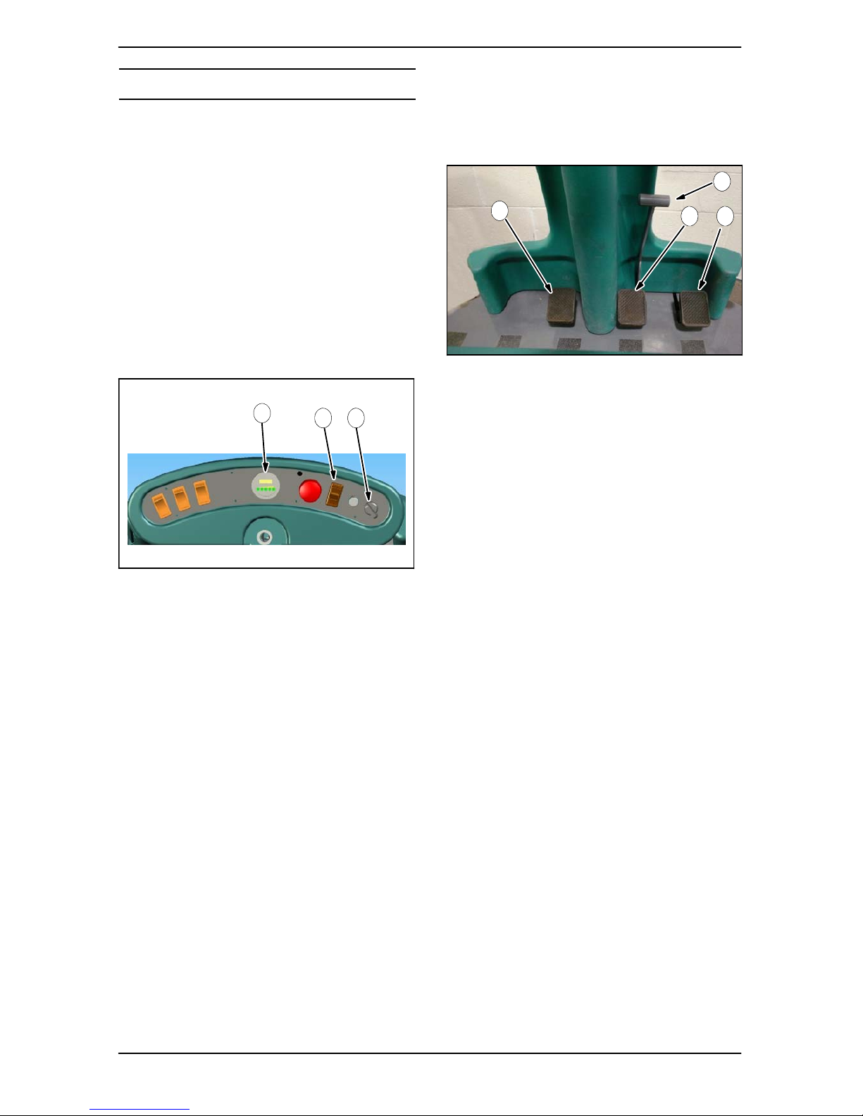
3. When starting machine:
-- Keep foot on brake and the pedal in
the top position.
4. When using machine:
-- Use brakes to stop machine.
-- Go slow on inclines and slippery
surfaces.
-- Use care when reversing machine.
-- Do not carry riders on machine.
-- Always follow safety and traffic rules.
-- Report machine damage or faulty
operation immediately.
5. Before leaving or servicing machine:
-- Stop on level surface.
-- Set parking brake.
-- Turn off machine and remove key.
6. When servicing machine:
-- Avoid moving parts. Do not wear loose
jackets, shirts, or sleeves when
working on machine.
-- Block machine tires before jacking up
machine.
-- Jack up machine at designated
locations only. Block machine up with
jack stands.
-- Use hoist or jack that will support the
weight of the machine.
-- Wear eye and ear protection if using
pressurized air or water.
-- Disconnect battery connections before
working on machine.
-- Avoid contact with battery acid.
-- Use Tennant supplied or equivalent
replacement parts.
7. When loading/unloading machine
onto/off truck or trailer:
-- Turn off machine.
-- Use truck or trailer that will support
the weight of the machine.
-- Use winch. Do not drive the machine
onto/off the truck or trailer unless the
load height is 380 mm or less from the
ground.
-- Set parking brake after machine is
loaded.
-- Block machine tires.
-- Tie machine down to truck or trailer.

3
S12 331361 (9--05)
The following safety labels are mounted on the
Machine in the locations indicated. If any Label
becomes damaged or illegible, install a new label
in its place.
FOR SAFETY LABEL -- LOCATED ON THE
SIDE OF THE OPERATOR COMPARTMENT.
FLYING DEBRIS LABEL -- LOCATED
ABOVE THE DRIVE AXLE.
BATTERY CHARGING LABEL -- LOCATED
IN THE BATTERY COMPARTMENT.

4S12 331361 (9--05)
OPERATION
OPERATOR RESPONSIBILITY
-The operator’s responsibility is to take care of
the daily maintenance and checkups of the
machine to keep it in good working condition.
The operator must inform the service
mechanic or supervisor when the
maintenance intervals are required as stated
in the MAINTENANCE section of this manual.
-Read this manual carefully before operating
this machine.
0
7
3
2
4
FOR SAFETY: Do not operate machine, unless
operation manual is read and understood.
-Check the machine for shipping damage.
Check to make sure the machine is complete
per shipping instructions.
-After operation, follow the recommended daily
and hourly procedures stated in the
MAINTENANCE CHART.
MACHINE DESCRIPTION
This sweeper is driven by electric motors.
This model operates by using a pivotable side
brush to direct the debris to the sweeping brush.
The sweeping brush projects the debris up into
the dust container.
Two side brushes may optionally be installed. If
necessary, the dust stirred up by the sweeping
brush is caught by the dust suction unit in a panel
filter inside the machine. The panel filter is
cleaned by an electrically controlled filter cleaning
device.

5
S12 331361 (9--05)
MACHINE COMPONENTS
J
I
Control Panel
A B C D E F G H
S
T
Q
R
L
M
N
P
O
K
A. Side brush switch
B. Main brush switch
C. Vacuum/filter cleaner switch
D. Battery condition display
E. Emergency stop switch
F. Directional switch
G. Horn push button
H. Key switch
I. Steering wheel
J. Front console
K. Side brush lever (standard right)
L. Side brush lever (optional left)
M. Driver’s seat
N. Main cover
O. Debris hopper
P. Drive wheel
Q. Side cover
R. Front trim panel
S. Pivotable side brushes
T. Front wheel with drum brake

6S12 331361 (9--05)
SAFETY DEVICES
This sweeper can only be started if:
-- the ignition key is set to the ON position;
-- the emergency stop switch is deactivated.
If the directional switch is set to reverse motion,
an audible signal is heard.
INITIAL STARTUP
This standard sweeper does not include batteries
or charger. The batteries and charger are optional.
If the batteries are not installed, perform the
following procedure.
1. Open the transport packaging, disengage the
seat switch cable and the main cover prop
rod.
2. With the help of an assistant, remove the
main cover by lifting it at the rear handle and
at the front of the seat support.
3. Install the batteries.
4. Connect the batteries. Refer to technical data
circuit diagram.
5. Replace the main cover.
6. Install the side brush
(See: Installing the Side Brushes).
The Sweeper is ready for use.
-- Ramp is not included.
NOTE: Use a unit ramp. The ramp must be
designed in such a way as to allow the front wheel
as well as the drive wheels to travel across it. If
this is not observed, damages to the sweeper
mechanics may occur.
If the drive pedal is activated during the starting
procedure, the machine will not propel if the
driver’s seat is not weighed down.

7
S12 331361 (9--05)
OPERATION
ADJUSTING THE DRIVER’S SEAT
Loosen the seat adjuster and shift the seat on the
seat support to adjust the seat position.
STARTING THE SWEEPER
1. Sit down in the driver’s seat.
NOTE: The Sweeper cannot be driven if the
driver’s seat is not weighed down.
2. Check the position of the directional switch.
NOTE: Forward position; the machine is set to
propel forward. Backward position; the machine is
set to propel in reverse.
A B
C
A. Directional switch
B. Key switch
C. Battery condition display
3. Insert the key into the key switch.
4. Turn the key switch.
NOTE: A red LED starts flashing on the battery
condition display indicating that the machine is
ready for operation. After a few seconds the
LED‘s will change to indicate the battery’s
charging condition.
5. Press the brake pedal.
6. Release the parking brake.
NOTE: An audible signal will sound when backing
the machine.
A
B
C D
A. Debris flap
B. Parking brake
C. Brake pedal
D. Accelerator
7. Press the accelerator pedal to adjust the
speed of the sweeper.

8S12 331361 (9--05)
SWEEPING
SAFETY INFORMATION
Provide adequate ventilation when using the
machine in closed rooms or buildings. Do not
sweep hazardous materials.
A B C
D
A. Side brush switch
B. Main brush switch
C. Vacuum/filter cleaner switch
D. Main sweeping brush lever
OPERATING THE MAIN BRUSH
1. Start the sweeper.
2. Lower the main brush with the main brush
lever.
3. Place the main brush switch in the ON
position. The indicator lamp on the switch
lights up. The main brush begins rotating.
4. Sweep as required.
5. To sweep larger pieces of debris, press the
debris flap as needed.
STOPPING THE MAIN BRUSH
1. Place the main brush switch in the OFF
position.
2. Raise the main brush with the main brush
lever.
OPERATING THE SIDE BRUSH(ES)
1. Start the Sweeper.
2. Place the side brush switch in the ON
position. The indicator lamp on the switch
lights up. The side brush(es) begins to rotate.
3. Lower the side brush with the side brush
lever.
STOPPING SIDE BRUSH OPERATING
1. Place the side brush switch in the OFF
position.
2. Raise the side brush with the side brush lever.
OPERATING THE VACUUM
The vacuum prevents dust formation during
sweeping operations.
1. Start the sweeper.
2. Place the vacuum/filter cleaner switch in the
top vacuum position.
NOTE: The indicator lamp on the switch lights up.
The vacuum begins operating.
NOTE: Do not operate vacuum when debris is
wet. This will cause damage to the vacuum fan.
Turn off the vacuum operation by placing the
switch in the middle OFF position.
A
B C
A. Filter cleaner position
B. Vacuum position
C. Middle OFF position
OPERATING THE FILTER CLEANER
The panel filter collects fine dust during sweeping
operation. The filter cleaner cleans the dust and
prevents the panel filter from being blocked by
debris.
1. Place the main brush switch in the OFF
position.
2. Place the vacuum/filter cleaner switch in the
middle OFF position.
3. Wait until fan stops.
5. Press and hold the switch in the filter cleaner
position for about 5--10 seconds.

9
S12 331361 (9--05)
TURNING OFF THE SWEEPER
1. Press and hold the brake pedal.
2. Lock the brake by pulling the locking lever
towards the driver’s seat.
NOTE: When the brake is released the brake
pedal must remain in pressed position.
3. Switch off all functions.
4. Raise the main brush and side brush(es) with
the levers.
5. Turn the key counterclockwise and remove it
from the key switch.
FOR SAFETY: Before leaving machine, stop
on a level surface, set parking brake, turn off
machine and remove key.
EMPTYING THE DEBRIS HOPPER
The debris hopper is where the debris is collected.
It is positioned at the back of the sweeper. The
debris hopper must be emptied after each use.
REMOVING THE DEBRIS HOPPER
1. Turn the debris hopper locking devices
upward.
2. Pull the debris hopper from the sweeper by
the handle until the front debris hopper guide
rails are free.
WARNING: Brush throws debris. Stop
motor before removing hopper.
FOR SAFETY: Before leaving or servicing
machine, stop on a level surface, set parking
brake, turn off machine and remove key.
B
C
A
D
E
A. Locking devices
B. Handle
C. Guide roller
D. Guide rail
E. Debris hopper guides
NOTE: At the back of the debris hopper two
guiding rollers are installed to make the removal
more easy.
3. Lower the debris hopper to the ground.
4. Remove the debris hopper completely from
the sweeper.
5. In order to empty the debris hopper use the
free hand to take hold of the handle.
6. The debris is discharged through the opening
at the front of the hopper.
7. Empty debris into appropriate containers only.
8. Dump heavy loads on floor or use an
assistant to help lift.
REINSERTING THE DEBRIS HOPPER
1. Position the debris hopper in front of the
sweeper opening.
2. Align the debris hopper front guides level with
guide rails.
3. Slide the debris hopper into the sweeper.
4. Turn the locking device downward.

10 S12 331361 (9--05)
REPLACING THE FILTER
1. Open the hood.
2. Lock hood securely using the hood prop.
A
A
A. Star handles
3. Loosen the top two star handles.
4. Swing up the top angular bracket.
5. Loosen the bottom two star handles.
6. Pull the filter out of the fixture.
POSITIONING THE FILTER
Filter shows the following symbol on the frame.
A
A. Filter seal
Make sure the filter is facing the right direction
when installing. The seal filter must show towards
the filter housing as shown.
INSTALLING THE FILTER
1. Place the filter into the lower angular bracket.
2. Swing the upper bracket over the filter.
3. Tighten the top star handles slightly.
4. Tighten star handles evenly crosswise so that
the filter snugly fits all around the seal.
5. Adjust the bolts and the nuts in a way that,
provides the filter with the best possible
Sealing inside the casing.
C
A
B
A. Angular brackets
B. Star handle
C. Filter
CLEANING THE SWEEPER
The sweeper is equipped with electrical
components.
NOTE: Moisture damages the electronic controls
of the machine. Moisture may lead to leak current
and short--circuits. Do not use high--pressure
cleaning devices.

11
S12 331361 (9--05)
SIDE BRUSHES
REMOVING THE SIDE BRUSH
FOR SAFETY: Before leaving or servicing
machine, stop on a level surface, set parking
brake, turn off machine and remove key.
1. Turn off the sweeper.
2. Raise the side brush with the side brush lever.
3. Lift up the side brush motor.
AB
C
D
E
A. Side brush motor
B. Side brush cover
C. Shaft with keyway
D. Flange base with feather key
E. Fastening screw
4. Loosen the fastening screw at bottom center
ofthesidebrush.
5. Pull the side brush down and off.
6. Replace the side brush.
INSTALLING THE SIDE BRUSH
1. Fasten the flange plate to the side brush. The
flange plate is equipped with a key. The side
brush motor shaft is equipped with a keyway.
2. Turn the side brush until the key fits snugly
into the keyway.
3. Slide the shim over the shaft of the side brush
motor.
4. Fasten the side brush to the shaft of the side
brush motor with the fastening screw.
ADJUSTING THE SIDE BRUSH
Normal wear requires additional adjustment of the
side brushes.
1. Turn off the sweeper.
2. Lower the side brush with the side brush
lever.
3. Loosen the bolts of the front panel.
4. Remove the front panel.
A
A. Bolts for the front panel
5. Loosen the bolt of the side brush level
adjustment.
6. Move the side brush to the desired position.
7. Tighten the bolt of the side brush level
adjustment.
A
A. Level adjustment bolt for side brush
8. Reinstall the front panel.

12 S12 331361 (9--05)
MAIN BRUSH
REMOVING THE MAIN BRUSH
FOR SAFETY: Before leaving or servicing
machine, stop on a level surface, set parking
brake, turn off machine and remove key.
1. Turn off the sweeper.
2. Lower the main brush with the main brush
lever.
3. Loosen the bolts of the left side cover.
A
A. Left side cover bolts
4. Loosen the brush plate knob.
5. Remove the main brush plate and open the
main brush door.
AB
DC
E
A. Brush plate knob
B. Main brush plate
C. Guide pins
D. Turning lever
E. Main brush door
6. Pull the main brush out of the machine and
remove any debris, strings, etc., from the
brush compartment, the brush, the drive pin
(see photo on the right) and the pick--up pin.
INSTALLING THE MAIN BRUSH
1. Push the main brush under the machine.
NOTE: Make sure the brush is facing the proper
direction (as shown below).
A
B
C
A. Forward direction
B. Direction of brush rotation
C. Brush keyway
2. Turn the main brush until the brush keyway
aligns with the drive pin on the far side of the
brush compartment (see photo below). Slide
the main brush in until it is snug over the the
drive pin, then close the main brush door.
3. Holding the main brush plate, rotate the
turning lever until the pick--up pin aligns with
the brush keyway.
AB
C
A. Main brush keyway
B. Drive pin
C. Pick--up pin
4. Install the main brush plate, aligning it over
the guide pins while pushing the pick--up pin
into the main brush.
5. Fasten firmly with the brush plate knob.
6. Reinstall the left side cover.

13
S12 331361 (9--05)
SETTING THE MAIN BRUSH PATTERN
For best cleaning results and to ensure the
highest possible device efficiency, the main brush
pattern should be properly set. The sweeping
pattern should be set to approximately 30--40 mm
on the floor.
CHECKING THE MAIN BRUSH PATTERN
1. Drive the sweeper to an area to be cleaned.
2. Turn the main brush on and lower it to the
floor.
3. Allow the main brush to operate for about one
or two minutes without moving.
4. Raise the main brush and turn it off.
5. Drive the sweeper forward a few meters.
6. The main brush track visible on the ground is
the main brush pattern.
ADJUSTING THE MAIN BRUSH PATTERN
1. Turn off the sweeper.
FOR SAFETY: Before leaving or servicing
machine, stop on a level surface, set parking
brake, turn off machine and remove key.
2. Lower the main brush.
3. Tilt the main cover forward and prop it open.
4. Adjust brush pattern with the forked lever or
cam adjuster as needed.
There are two ways to make adjustments to the
main brush pattern.
Fine adjustments can be made by moving the
forked lever to a different hole. To move the
forked lever, open the quick--release clip. Then
the pin in the lever can be moved to the desired
position. Close the clip when finished with the
adjustment.
Course adjustments can be made with the cam
adjuster. Loosen the knob to make an
adjustment. Tighten the knob when finished with
the adjustment.
A
C
B
A. Forked lever adjuster
B. Quick--release clip
C. Cam adjuster

14 S12 331361 (9--05)
BATTERIES
Four batteries supply the sweeper with electrical
power. The charging condition of the batteries is
indicated by the battery condition display on the
control panel.
A
B
A. Battery--condition display
B. LED’s
When the sweeper is switched on the red LED
flashes five times. Subsequently the electronic
system of the sweeper carries out a self--testing
operation of the battery charging level. The result
of this self--testing is displayed by the 5 LED‘s.
Information provided by LED indicators on the
battery condition display:
charging condition of battery
condition fully charged
operating/charging condition uncritical
operating/only for a short time longer
lit LED
operating/soon critical
operating/critical
Red
Yellow
Green
Green
Green
WARNING: Batteries emit hydrogen gas.
Explosion or fire can result. Keep
sparks and open flame away. Keep
covers open when charging.
FOR SAFETY: Before leaving or servicing
machine, stop on level surface, set parking
brake, turn off machine, and remove key.
FOR SAFETY: When maintaining or servicing
machine, avoid contact with battery acid.
CHARGING THE BATTERIES
1. Turn off the sweeper.
2. Open the hood.
3. Secure the hood position.
4. Disconnect the power--supply--connector from
the Charing connector.
5. Connect the charging device to the charging
plug of the sweeper.
6. Check the water level in all the battery cells. If
the level is low, add just enough distilled water
to cover the battery plates. DO NOT
OVERFILL. The batteries can overflow during
charging due to expansion.
NOTE: Make sure the battery caps are in place
while charging.
FOR SAFETY: When maintaining or servicing
machine, avoid contact with battery acid.

15
S12 331361 (9--05)
7. Connect the plug of the charger to a power
supply connector.
A
BC
A. Sweeper connector
B. Battery connector
C. Charger connector
The charging process lasts for approx. 10 hours
when the batteries have been completely depleted
(with the device originally provided by the
manufacturer).The original charging device of the
manufacturer can/should remain connected after
charging is completed, because it is equipped with
a charge saver allowing it to provide highest
possible battery capacities even after long periods
of standstill.
Be careful only to use the sweeper if there is
enough voltage left in the batteries. The machine
automatically switches itself off, if the batteries are
discharged to such a degree that damages may
occur (excessive discharge protection).
In this case: Switch off all functions and let the
machine stand for about one or two minutes.
Switch on the machine again and drive to the
charging device (without sweeping operation!)
Charge batteries immediately to avoid possible
damages.
BRAKE
The brake (drum brake) acts on the front wheel
and is controlled via the brake cable by the brake
pedal.
The brake adjustment is situated on the right side
of the front wheel facing in driving direction.
ADJUSTING THE BRAKE
FOR SAFETY: Before leaving or servicing
machine, stop on a level surface, set parking
brake, turn off machine and remove key.
1. Hold the adjustment nut of the cable in place
with a wrench.
2. Loosen the back nut of the adjustment nut.
3. Push the brake lever upward until the brake
lever is fully engaged.
4. Hold the brake lever in this position.
5. Tighten the back nut of the adjustment nut.
6. Now conduct a brake--test.
B
C
D
F
E
A
G
A. Wire guide
B. Brake conduit
C. Adjustment nut
D. Back nut
E. Brake cable
F. Brake cable lock
G. Brake lever
BRAKE CHECK
FREE MOVEMENT OF FRONT WHEEL
You must be able to move the sweeper by
pushing when the brake is released. The front
wheel must not be blocked. Brakes that are set
too tightly damage the brake drum.
CORRECT OPERATING OF BRAKE
Carefully drive a few meters at moderate speed.
Press the brake pedal.The sweeper must stop. If
the brake check should not render a satisfying
result the setting procedure must be repeated.
FURTHER SETTING POSSIBILITY
The cable no longer allows tightening in the way
described above any longer.
1. Loosen the cable lock.
2. Lift the brake lever up until it is fully engaged.
3. Hold the brake lever in the “up” position.
4. Pull the brake cable down and push the
brake lever upward.
5. Fasten the brake cable lock.
6. Repeat the brake check.

16 S12 331361 (9--05)
CIRCUIT BREAKERS
The resetable circuit breakers are positioned on
the right side under the hood, facing in driving
direction.
FOR SAFETY: Before leaving or servicing
machine, stop on a level surface, set parking
brake, turn off machine and remove key.
A
B C D
FE G
A. Forward motion
B. CB1 Vacuum fan
C. CB2 Main brush
D. CB3 Side brush
E. CB4 Horn, buzzer, beacon
F. CB5 Traction
G. CB7 Battery monitor/Relays
To reset a circuit breaker simply press the black
part of the circuit breaker back into the snap--in
position. Make sure that the cause for the circuit
breakers to be disengaged will be identified and
fixed by a qualified person.
STEERING
The steering transferal to the front wheel is
managed by a chain and two chain sprockets.
Grease the chain sprockets at regular intervals.
See maintenance chart.
BRUSH DRIVE
The brush drive is located on the right side of the
sweeper facing the driving direction. The main
brush is driven by an electric motor via a chain.
The chain is deflected by a sprocket and guided
over the sprockets of the brush drive. A spring
biased chain tensioner keeps the chain tight.
Grease the sprockets at regular intervals. See
maintenance chart. To grease the sprockets, open
the hood and remove the side trim panel.
A
B
A. Main brush sprocket guard
B. Sprockets
TRANSPORTING THE MACHINE
For the safe transport of the sweeper in a crate or
on a pallet: tie down the machine by fixing two
straps as shown below.
The front strap should be fixed across the frame
along the foot--rest.The rear strap should be fixed
across the frame along the area below the
vacuum fan. Protect the paint of the frame by
using a soft cloth or cardboard--box.
FOR SAFETY: make sure to use straps that
withstand an increased load due to vibrations
of the machine during transport.
AB
A. Front strap
B. Rear strap

17
S12 331361 (9--05)
MAINTENANCE CHART
DAILY MAINTENANCE
-- Charge battery.
-- Check battery acid level, if required add
distilled water.
-- Check if machine is damaged or impaired in
any way.
-- Check condition of dust filter and clean if
necessary.
-- Empty debris hopper.
AFTER 50 HOURS OF OPERATION
-- Check if battery leaks acid.
-- Clean and grease battery poles.
-- Check the main brush for wear or damage.
Clean or replace if required.
-- Check main brush pattern, readjust if
required.
-- Check if side brush adjustment is worn, if
required readjust or replace.
-- Search brush tunnel for jammed particles and
seized up dirt that may narrow the brush
tunnel and obstruct free brush movement.
AFTER 100 HOURS OF OPERATION
-- Check battery cable isolation, replace cables
if required.
-- Check if battery cable connections are tight.
-- Grease steering chain.
-- Grease brush drive chain.
-- Clean dust filter, replace if necessary.
-- Search vacuum for obstacles, clean if
necessary.
-- Conduct trial run to check all operating
elements.
-- Check if brush drive chain is stretched or
loosened.
-- Check all bearings for wear.
-- Check if seals are damaged or dislocated.
AFTER 200 HOURS OF OPERATION
-- Check operation of electric motors.
-- Check if carbon brushes are worn, replace if
required.
-- Check steering clearance, tighten chain if
required.
-- Check all electrical system components for
dirt. Clean if required.

18 S12 331361 (9--05)
MACHINE TROUBLESHOOTING
Problem Cause Remedy
No operating display at
control panel
EMERGENCY OFF not switched
on
Turn EMERGENCY OFF switch
counter clockwise
Key switch not switched on Turn key switch and check correct
load
Fault in electrical wiring Check plug connections
Battery charge empty Charge battery
No operation of propelling
drive inspite of display at
control panel
Accelerator was depressed at start Release accelerator and re--start
Circuit breaker 5 or 7 or fuse
6 defective
Reset circuit breaker / replace fuse
Fault in electrical connections Check plug connections and
compare
Problems in electronic control Have control checked by
authorized person
No operation of one of the
electrical components
Circuit breaker inactive Reset circuit breaker
Fault in electric connections Check plug connections of
corresponding system component:
check especially sweeping brush
whether obstructed by bands,
cables, strings
Sweeping result
unsatisfactory
Side brush(es) or main sweeping
brush not lowered
Lower
Side brush(es) or main brush worn Adjust
Brush tunnel clogged by dirt Check if brush trim panel is
impaired by jammed debris
Main brush does not operate Install brush correctly
Check to see if the motor rotates
Dust formation too great If required switch off side brushes
Vacuum fan does not operate Check if electrically defective
Filter excessively dirty Clean filter
Filter not correctly fitted Check for tight fit
Circuit breaker of the
sweeping brush does not
remain set
Main brush is jammed by dirt,
cords, strings etc.
Dismount and clean brush
Circuit breaker of the side
brushes does not remain set
Side brushes are jammed by dirt,
cords, strings or debris
Check side brushes and remove
obstacles
Circuit breaker of vacuum
Does not remain set
Vacuum fan does not move freely Check fan and remove any
obstruction
Circuit breaker of propelling
drive does not remain set
Drive wheels obstructed Jack up the sweeper check
differential operation of wheels and
free running
Table of contents
Other Tennant Blower manuals

Tennant
Tennant 810 LPG User manual

Tennant
Tennant S20 Gas User manual

Tennant
Tennant S7 User manual

Tennant
Tennant 3640E User manual

Tennant
Tennant sentinel User manual

Tennant
Tennant S6 User manual

Tennant
Tennant 6100 User manual

Tennant
Tennant A60 User manual

Tennant
Tennant S7 User manual

Tennant
Tennant CENTURION User manual

Tennant
Tennant S680 User manual

Tennant
Tennant A80 User manual

Tennant
Tennant 6100E Training manual

Tennant
Tennant SweepSmart S20 ELECTRIC User manual

Tennant
Tennant 614214-Tennant 3610 Product manual

Tennant
Tennant S6+ User manual

Tennant
Tennant 250 Product manual

Tennant
Tennant 6400 User manual

Tennant
Tennant 6550 User manual

Tennant
Tennant S3 Product manual